
nstallati
nst cti
lectric
Drye
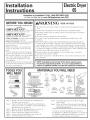
Questions on Installation? Call" 1-800-GECARES (US)
or Visit our Web site at: www.GEAppliances.com (US)
BEFOREYOU BEGIN
Read these instructions completely and
carefully.
IMFORTANT- S.,,ethese
e
instructions fbr local inspector's use.
"IMPORTANT- Obse,,,e
all governingcodes and ordinances°
* Note to Installer- Be sure to leave these
instructions with the custotner.
* Note to Customer - Keep these instruc>
ions with your Use and Care Book for
furore reference.
* Before the old dryer is removed flom
service or discarded, remove the d_Ter
door.
* Service infbrmation and the wiring dia-
gram are located in the control console.
* Do not allow children on or in the appli-
ance. Close supe_wision of children is
necessa_ T when the appliance is used
near children.
* Install the (bTer where the temperature
is above 50°F for satisfilctory operation of
the d_Ter control system.
kWARN I N G RIsKOF
* To reduce the risk of severe i_i m T or death, fbllow all installation instruc-
tions.
* Clothes d_Ter insmlla6on must be performed by a qualified installer.
* Install the clothes d_Ter according to these instructions and in accordance
with local codes.
* This d_Ter must be exhausted to the outdoors.
* Use only 4" rigid metal duc6ng for exbaus6ng the clothes d_Ter to the
outdoors.
* DO NOT install a clothes d,Ter with flexible plastic ducdng materials. If
flexible metal (semi-rigid or fbil-type) duct is installed, it must be UL listed
and installed in accordance with the instructions found in "Connecting The
D,Ter To House Vent" on page 5 of this manual. Flexible venting materials
are known to collapse, be easily crushed, and trap lint. These conditions will
obstruct dryer airflow and increase the risk of fire.
* Do not install or store this appliance in any location where it coukt be
exposed to water and or weather.
* Save these instructions. (Installers: Be sure to leave these instructions with
the customer).
NOTE: installation and service of this dryer requires basic
mechanical and electrical skills, it is your responsibility to
contact a qualified installer to make the electrical connections.
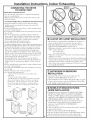
TOOLS YOU
WiLL NEED
SLIPJOINTPLIERS
FLATBLADESCREWDRIVER
PHILLIPSSCREWDRIVER
%
MATERIALS YOU
)
4" DIA.METALDUCT
(RECOMMENDED)
4"DIA,FLEXIBLEMETALSEMI-RIGID)
ULLSTEDTRANSTONDUCT
(IFNEEDED)
KITWXO8X10077(INCLUDES2ELBOWS)
4"DUCT
CLAMPS(2)
OR
4"SPRING
CLAMPS(2)
%
4"DIA.METAL
ELBOW
4"DIA.FLEXIBLEMETALFOILTYPE)
ULLSTEDTRANSTONDUCT
(IFNEEDED.)
DUCTTAPE
WiLL NEED
EXHAUST SAFETY
HOOD GLASSES
3/4"STRAIN
GLOVES RELIEF
ULRECOGNIZED
DRYERPOWER
CORDKIT
(NOTPROVIDED
WITHDRYER)
ULRATED
120/240V,30A
WITH3OR4PRONGS.
IDENTIFYTHEPLUG
TYPEASPERTHE
HOUSERECEPTACLE
BEFOREPURCHASING
LINECORD.
Step 1
Step 2
Step 3
Step 4
Step 5
Step 6
Step 7
Prepare the Area and Exhaust for Installation of
New Dryer (see section 1).
Check and Ensure the Existing External Exhaust is
Clean (see sec6on 1) and Meets Attached Installa6on
Specifications (see sec6on 3).
Remove the Foam Shipping Pads (see sec6on 1).
Move the DtTer to the Desired Location.
Connect the Power Supply (see secdon 2).
Connect the External Exhaust (see secdon 4).
Level Your D_Ter (see sec6on 5).
Step 8
Step 9
Check the Operation of the Power Supply
an d Ve n tin g.
Place the Owners Manual and the Installation
Instructions in a Locadon Where They Will Be
Noticed By the Owner.
For Alcove or Closet Installation, see section 6.
For Bathroom or Bedroom Installation, see section 7.
For Mobile or Manufi_cmred Home see, section S.
For side or bottom exhaust, see section 9.

Installation instructions
Minimum Clearance Other Than Alcove or Closet Installation
Minimum clearance m combustible surfhces and for air opening are: 0 in. clearance bod_ sides and 1 in. rear. Consideration
must be given m provide adequate clearance ff)r installation and service.
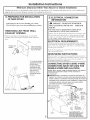
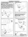
I-f] PREPARING FOR iNSTALLATiON
OF NEW DRYER
TIP: Install your dryer before installing your washer,
This will allow better access when installing dryer exhaust.
REMOVING LiNT FROM WALL
EXHAUST OPENING
* Remove and discard existing plastic or metal foil
transition duct and replace with UL listed transition
duct°
WALL
/
INTERNALDUCT
CHECKTHATEXHAUST
OPENING DAMPEROPENS
ANDCLOSESFREELY.
TILTTHEDRYERSIDEWAYS
ANDREMOVETHEFOAM
SHIPPINGPADSBY
PULLINGATTHESIDES
ANDBREAKINGTHEM
AWAYFROMTHEDRYER
LEGS.BESURETO
REMOVEALLOFTHE
FOAMPIECESAROUND
THELEGS.
2
[_ ELECTRICAL CONNECTION
iNFORMATiON
A
WARNING- TO REDUCE THE RISK OF
FIRE, ELECTRICAL SHOCKAND PERSONAL
INJURY:
e DO NOT USE AN EXTENSION CORD OR AN
ADAt_ER PLUG WITH THIS APPLIANCE.
Dwer must be electrically grounded in accordance with
local codes and ordinances, or in the absence of local
codes, in accordance with the NATIONAL ELECTRI-
CAL CODE, ANSI/NFPA NO. 70.
ELECTRICAL REQUIREMENTS
This dryer must be connected to an individual branch circuit,
protected by the required time-delay fllses or circuit breakers. A
Ibm or three-wire, single phase, 120/240V or 120/208V, 60Hz,
30 amp circuit is required.
If the electric supply does not meet the aboxe specifications, then
call a licensed electrician.
GROUNDING INSTRUCTIONS
This dryer must be connected to a grounded metal, permanent
wiring system, or an equipmen/-grounding conductor must be run
with the circuit conductors and connected to the equipment-
grounding terminal on the appliance.
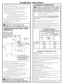
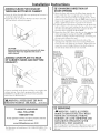
CONNECTING DRYER USING 4-WIRE
CONNECTION (MUST BE USED FOR
MOBILE HOME INSTALLATION)
NOTES: Since January 1,1996, the National Electric code requires
that the new constructions utilize a 4-wire connection to
an electric dryer
t_WARNING:only a 4-conductor cord shah be used when the
appliance is installed in a location where grounding through the
neutral conductor is prohibited. Grounding through the neutral is
prohibited for the new branch-circuit installations, mobile homes,
recreational vehicles, and areas where local codes prohibit
grounding through the neutral conduction.
REMOVEGROUNDSTRAP -
ANDDISCARD,KEEPGREEN
HOT-"'_
GROUNDSCREW WIRE RELOCATEGREEN
GROUNDSCREW
HERE
GREENOR

Installation
i. Turn off the circuit breaker (s) (30 amp) or remox e tlle ch):er's
circuit fuse at the electrical box.
2. Be sure the ch):er cord is unplugged from tile wall receptacle.
3. Remox e tile power cord coxer located at the lower back.
4. Remox e and discard ground strap. Keep tlle green
ground screw for step 7.
5. Install 3/4 in. LL recognized strain relief to power
cord entl_ hole. Bring power cord through strain relief.
6. Comlect power cord as follows:
A. Comlect the 2 hot lines to tile outer screws of
tlle terminal block (marked L1 and L2).
B. Com_ect tlle neutral (white) line to tile center of
tile terminal block (marked N).
7. Attach ground wire of power cord with tile green ground
screw (hole aboxe strain relief bracket). Tighten all
terminal block screws (3) completely.
8. Properly secure power cord to strain relief.
9. Reinstall tile co_ er.
_ILWARNING: NEVER LEAVE THE
COVER OFF OF THE TERMINAL BLOCK,
CONNECTING DRYER USING 3-WIRE
CONNECTION
IFREQUIRED,BYLOCALCODE,
INSTALLEXTERNALGROUND
(NOTPROVIDED)TOGROUNDED
METAL,COLDWATERPIPE,OR
OTHERESTABLISHEDGROUND
DETERMINEDBYAQUALIFIED
ELECTRICIAN.
GREEN GROUND
GROUND STRAP
SCREW HOT
WIRE
STRAINRELIEF
BRACKET
_ 3/4",UL
RECOGNIZED
RELIEF
NEUTRAL
HOT
(White) WIRE
3#10AWGMINIMUMCOPPER
COVER CONDUCTORSOR120/240V30APOWER
SUPPLYCORDKITMARKEDFORUSE
WITHDRYERS&PROVIDEDWITHCLOSED
LOOPORSPADETERMINALSWITH
UPTURNEDENDS(NOTSUPPLIED).
i. Tm'n off tile circuit breaker(s) (30 amp) or remo_ e tile ch_er's
circuit fuse at the electrical box.
2. Be sure the ch_er cord is unplugged Kom the wall.
3. Remoxe the power cord coxer located at tile lower back.
4. Install 3/4 in. LL recognized strain relief to power cord
entl?_ bole. Bring power cord through strain relief.
5. Connect power cord as follows:
A. Com_ect the 2 hot lines to the outer screws of tile
terminal block (marked L1 and L2).
B. Com_ect the neutral {white) line to tile center of
the terminal block {marked N).
6. Be sure grotmd strap is com_ected to neutral (center)
terminal of block and to green ground screw on cabinet
rear. Tighten all terminal block screws (3) completely.
7. Properly secure power cord to strain relief.
S. Reinstall tile co_ er.
A
,AHb_WARNING: NEVER LEAVE THE
COVER OFF OF THE TERMINAL BLOCK.
Instructions
3
EXHAUST INFORMATION
_WARNING - IN CANADA AND IN THE UNITED
STATES, THE REQUIRED EXHAUST DUCT DIAMETER
IS 4 IN (102ram). DO NOT USE DUCT LONGER
THAN SPECIFIED IN THE EXHAUST LENGTH TABLE.
Lsing exhaust longer than specified length wilh
" Increase the drying times and tile energy cost.
, Reduce the ch)_er life.
, Accumulate lint, creating a potential fire hazard.
The correct exhaust installation is YOUR RESPONSIBILITY.
Problems due to incorrect installation are not covered
by the warranty.
Remove and discard existing plastic or metal foil transition
duct and replace with LL listed transition duct.
Tlle MAXIML M ALLOWABLE duct length and number of
bends of the exhaust system depends upon the type of duct,
number of turns, the type of exhaust hood (wall cap), and all
conditions noted below. The maximum duct length for rigid
metal duct is shown in the table below.
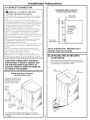
EXHAUST LENGTH
RECOMMENDED MAXIMUM LENGTH
Exhaust Hood Types
Recommended Use only for short
run installations
4" DIA.
_ 2-1/2"
No. of 90-0 Rigid Rigid
Elbows Metal Metal
0 90 Feet 60 Feet
1 60 Feet 45 Feet
2 45 Feet 35 Feet
3 35 Feet 25 Feet
4 25 Feet 15 Feet
EXHAUST SYSTEM CHECK LIST
HOOD OR WALL (AP
• Terminate in a manner to prevent back drafts o1 entry of birds or
other wildlife.
• Termination should present minimal resistance to the exhaust air flow
and should require little or no maintenance to prevent clogging.
• Never install a screen in or over the exhaust duct.This could cause lint build up.
• Wall caps must be installed at least 12 in. above ground level or any other
obstruction with the opening pointed down.
SEPARATION OF TURNS
For best performance, separate all turns by at least 4 ft. of straight duct,
including distance between last ttHn and exhaust hood.
TURNS OTHER THAN 90°
* Oile tt_in of 45 ° or less may be ignored.
* TWO45° ttH'i1S should be treated as one 90 ° ttH'i1.
, Each ttH'n over 45 ° should be treated as one 90 ° ttwn.
SEALING OF JOINTS
• _Mljoints should be tight to avoid leaks. The male end of each section of
duct must point away flom the dryer.
Do not assemble the d uctwork with fasteners that extend into the d t_ct.
They will serve as a collection point for lint.
Duct joints can be made air and moisture-tight by wrapping the
overlapped joints with d t_ct rope.
Horizontal runs should slope down toward the outdoors _½inch per foot
INSULATION
Duct work that runs through an unheated area or is near air conditioning
should be insulated to reduce condensation and lint build-up.

Installation
[-4-]EXHAUST CONNECTION
_ WARNING - TO REDUCE THE RISK
OF FIRE OR PERSONAL INJURY:
* This clothes dIyer must be exhausted to the outdoors.
* Use only 4" rigid metal ducting for the home exhaust
duct.
. Use only 4" rigid metal or UI,-listed flexible metal
(semi-rigid or foil-type) duct to connect the d_Ter to the
home exhaust duct. It must be installed in accordance
with the instructions found in "Connecting The Dryer
To House Vent" on page 5 of this manual.
* Do not terminate exhaust in a chimney, a wall, a
ceiling, gas vent, crawl space, attic, under an enclosed
floor, or in any other concealed space of a building°
The accumulated lint could create a fire hazard.
* Never terminate the exhaust into a common duct with
a kitchen exhaust system. A combination of grease and
lint creates a potential fire hazard.
* Do not use duct longer than specified in the exhaust
length table. Longer ducts can accumulate lint,
creating a potential fire hazard.
* Never install a screen in or over the exhaust duct. This
will cause lint to accumulate, creating a potential fire
hazard.
* Do not assemble ducta, vork with any fasteners that
extend into the duct. These fasteners can accumulate
lint, creating a potential fire hazard.
* Do not obstruct incoming or exhausted air.
* Provide an access for inspection and cleaning of the
exhaust system, especially at turns and joints. Exhaust
system shall be inspected and cleaned at least once a year.
THiS DRYER COMES READY FOR REAR
EXHAUSTING. iF SPACE iS LiMiTED, USE
THE iNSTRUCTiONS iN SECTION 9 TO
EXHAUST DIRECTLY FROM THE SIDES OR
BOTTOM OF THE CABINET.
STANDARD REAR EXHAUST
{Vented at floor level)
FORSTRAIGHTLINEINSTALLATION,
CONNECTTHEDRYEREXHAUSTTO
THEEXTERNALEXHAUSTHOOD
USINGDUCTTAPEORCLAMP.
EXTERNAL
DUCT
OPENING
DUCTTAPEOR
DUCTCLAMP
4"METALDUCT
(CUTTOPROPER
LENGTH)
DUCTTAPEOR
DUCTCLAMP
NOTE:WESTRONGLYRECOMMENDSOLIDMETALEXHAUSTDUCTING.
HOWEVER,IFFLEXIBLEDUCTINGISUSEDITMUSTBEUL-LISTEDMETAL
NOTPLASTIC.
instructions
STANDARD REAR EXHAUST
{Vented above floor level)
ELBOWHIGHLY
RECOMMENDED--
=
ELBOWHIGHLY
_ RECOMMENDED
RECOMMENDED
CONFIGURATION
TOMINIMIZE
EXHAUST
BLOCKAGE.
NOTE: ELBOWS WiLL PREVENT DUCT
KiNKiNG AND COLLAPSING.
[_ LEVELING AND STABiLiZiNG
YOUR DRYER
STANDTHEDRYERUPRIGHTNEARTHEFINALLOCATIONANDADJUST
THE4LEVELINGLEGS,ATTHECORNERS,TOENSURETHATTHEDRYER
ISLEVELFROMSIDETOSIDEANDFRONTTOREAR.
LEVEL
FRONT-TO-BACK.
LEVEL
SIDE-TO-SIDE.
4LEVELING
LEGS
4

Installation instructions, indoor Exhausting
CONNECTING THE DRYER
TO HOUSE VENT
RIGID METAL TRANSITION DUCT
* For best dxying perfk_rmance, a rigid metal transition
duct is recommended.
* Rigid metal transitions ducts reduce the risk of crush-
ing and kinking.
UL-LISTED FLEXIBLE METAL (SEMI-RIGID) TRANSITION DUCT
* If rigid metal duct cannot be used, then Ul,-listed
flexible metal (semi-rigid) ducting can be used (Kit
WX08X10077).
* Never install flexible metal duct in walls, ceilings, floors
or other enclosed spaces.
* Total length of flexible metal duct should not exceed 8
feet (2.4m).
* For many applications, installing elbows at both the
diyer and the wall is highly recommended (see illustra-
tions below). Elbows allow the d_yer to sit close to the
wall without kinking and or crushing the transition
duct, maximizing d,ying perf_rmance.
* Avoid resting the duct on sharp objects.
UL-LISTEDFLEXIBLEMETAL(FOIL-TYPE)TRANSITION DUCT
* In special installations, it may be necessai T to connect
the d_Ter to the hot_se vent using a flexible metal (fkfil-
type) dt_ct. A UL-listed flexible metal (fkfil-type)dt_ct
may be t]sed ONIX in installations where rigid metal or
flexible metal (semi-rigid) ducfing cannot be used AND
where a 4" diameter can be maintained throughout the
entire length of the transition dt_ct.
* In Canada and the United States, only the flexible
metal (f_il-type) ducts that comply with the "Outline f_r
Clothes D_yer Transition Duct Subject 2158A" shall be
used.
*Never install flexible metal duct in walls, ceilings, floors
or other enclosed spaces.
*Total length of flexible metal duct should not exceed 8
feet (2.4m).
*Avoid resting the duct on sharp objects.
*For best drying perf_rmance:
]. Slide one end of the duct over the clothes dryer
outlet pipe.
2. Secure the duct with a clamp.
3. With the d_yer in its permanent position, extend the
duct to its fifll length. Allow 9" of duct to overlap the
exhaust pipe. Cut offand remove excess duct. Kee I)
the duct as straight as possible t_r maximum airflow.
4. Secure the duct to the exhaust pipe with the other
clamp.
ELBOWHIGHLY
RECOMMENDED
__ SHIGHLY I
MENDED
ALCOVE OR CLOSET iNSTALLATiON
* If yore" dlTer is approved for installation in an alcove or
closet, it will be stated on a label on the dryer back.
° The dryer MUST be vented to the outdoors. See the
EXHAUST INFORMATION sections 3 & 4.
* Minimmn clearance between duer cabinet and adjacent
walls or other surfaces is:
0 in. either side
3 in. Kont and rear
* Minimmn vertical space from floor to overhead cabinets,
ceiling, etc. is 52 in.
* Closet doors must be iouvered or othetwvise ventilated and
must contain a minimum of 60 sq. in. of open area equally
distributed. If the closet contains both a washer and a
duet, doors must contain a minimum of 120 sq. in. of open
area equally distributed.
BATHROOM OR BEDROOM
INSTALLATION
* The dryerMU ST be vented to the outdoors. See
EXHAUST INFORN_TION section 3 & 4.
* The installation must conform with local codes or, in the
absence of local codes, with the NATIONAL ELECTRI-
CAL CODE, ANSI/NFPA NO. 70.
5
FSqMOBILE OR MANUFACTURED
HOME INSTALLATION
° Installation must conform to the MANUFACTURED
HOME CONSTRUCTION & SAFETY STANDARD,
TITLE 24, PART 32-80 or, when such standard is not
applicable, with %MERICAN NATIONAL STANDARD
FOR MOBILE HOME, ANSI/NFPA NO. 501B.
° The dryer MU ST be vented to the outdoors with the
termination securely fastened to the mobile home
structure. (See EXHAUST INFORMATION
section 3 & 4.)
* The vent MUST NOT be terminated beneath a mobile or
mam_factured home.
* The vent duct material MU ST BE METAL.
* Do not use sheet metal screws or other fastening devices
which extend into the interior of the exhaust vent.
* See section 2 for electrical connection information.

Installation Instructions
I-9-]DRYER EXHAUST TO RIGHT, LEFT
OR BOTTOM CABINET
A
WARNING- BEFORE PERFORMING
THIS EXHAUST INSTALLATION, BE SURE
TO DISCONNECT THE DRYER FROM ITS
ELECTRICAL SUPPLY. PROTECT YOUR
HANDS AND ARMS FROM SHARP EDGES
WHEN WORKING INSIDE THE CABINET.
BE SURE TO WEAR GLOVES
REMOVE
SCREW
ANDSAVE.
REMOVE
DESIRED
KNOCKOUT
(ONEONLY).
Detach and remove the bottom, right or left side knockout
as desired. Remove the screw inside the dryer exhaust duct
and save. Pull the duct out of the dryer.
FIXINGHOLE
\
B A
9"
Cut the duct as shown and keep portion A.
TAB LOCATION
BENDTAB
UP45o
Through the rear opening, locate the tab in the middle of
the appliance base. Lift the tab to about 45° using a fiat
blade screwdriver.
6
ADDING NEW DUCT
FIXING
HOLE
PORTION"A"
RIGHTOR
LEFTSIDE
EXHAUST
Reconnect the cut portion (A) of the duct to the blower
housing. Make sure that the shortened duct is aligned with
the tab in the base. Use the screw saved previously to secure
the duct in place through the tab on the appliance base.
ADDING ELBOW AND DUCT FOR
EXHAUST TO LEFT OR RIGHT
SIDE OF CABINET
Preassemble 4" elbow with 4" duct. Wrap duct tape
around joint.
Insert duct assembly, elbow first, through the side opening
and connect the elbow to the dryer internal duct.
CAUTION: Be sure not to pull or damage the
electrical wires inside the dryer
when inserting the duct.
J_
EXHAUSTCAN
BEADDEDTO
LEFTORRIGHTSIDE
DUCT
. TAPE
...... J-
Apply duct tape as shown on the joint between the dryer
internal duct and the elbow.
DUCT
CAUTION:
Internal duct joints must be
__ secured with tape, otherwisethey may separate and cause
a safety hazard.

Installation
ADDING ELBOW FOR EXHAUST
THROUGH BOTTOM OF CABINET
* Insert tile elbow through the rear opening and connect it
to the dryer internal duct.
* Apply duct tape oil thejoim between tile dryer internal
duct and elbow, as shown oil page 6.
CAUTION:
Internal duct joints must be secured with tape,
otherwise they may separate and cause a
safety hazard.
ADDING COVER PLATE TO REAR
OF CABINET (SIDES AND BOTTOM
EXHAUST)
PLATE
÷
(KITWE1M454)
Connect standard metal elbows and ducts to complete the
exhaust system. Cover back opening with a plate (Fdt
WEIM454) available from your local service provider.
Place dryer in final location.
_ WARNING-NEVER LEAVE THE BACK ]
OPENING WITHOUT THE PLATE. (KitWglM454)
Instructions
CHANGING DIRECTION OF
DOOR OPENING
1. Open the door and remove the filler plugs opposite the
hinges. With the door completely open, remove the
bottom screws from each hinge on the dryer face. Insert
these screws about half way into the TOP holes, for each
hinge on the opposite side (where you removed the filler
plugs). Apply firm pressure to get the screw started.
2. Loosen the top screws from each hinge on the dryer face
half way. With one hand hoMing the top of the door and
the other hand holding the bottom, remove the door
from the dD'er by lifting itUP and OUT.
3. Rotate the door 180 °. Insert the door on the opposite side
of the opening by moving the doorlN and DOWN
mltil the top hinge and the bottom hinge are resting on
the top screws inserted in step 1.
4. Remove the remaining screws from the side of the
opening from which the door was removed. With these
screws secure each hinge at the bottom. Tighten the two
top screws on each hinge. Reinsert the plastic plugs on
the side from which the door was removed.
REMOVETHE
BOTTOMSCREW
FROMEACHHINGE
ONTHEDRYER
_.__FAC_
LOOSENTHETOP
SCREWSFROM
EACHHINGEON
THEDRYERFACE
HALFWAY.
MOVETHEDOORINAND
DOWNUNTILTHETOPHINGE
ANDTHEBOTTOMHINGEARE
RESTINGONTHETOPSCREWS
INSERTEDINSTEP1.
SECUREEACHHINGE
ATTHEBOTTOMAND
TIGHTENTHETWOTOP
SCREWSOFEACHHINGE.
TO REGISTER YOUR DRYER
CALL TOLL-FREE
1-888-269-1192
Prompt registration confirms your right to protection under the
terms of your warranty.
www.GEAppliances.com (US)
For Questions on Installation, Call: 1-800-GECARES (US)
5(t(t,\4 _tiPO05 Re'J) Pub # 31 16224 7
SERVICING
WARNING- LABEL ALL WIRES
PRIOR TO DISCONNECTING WHEN
SERVICING CONTROLS. WIRING
ERRORS CAN CAUSE IMPROPER AND
DANGEROUS OPERATION AFTER
SERVICING/INST ALIATION.
For servicing t)hone numbers for replacement parts, and
other information, refer to Owner's Manual or visit our
Web sire.

Notes
-
 1
1
-
 2
2
-
 3
3
-
 4
4
-
 5
5
-
 6
6
-
 7
7
-
 8
8


Ask a question and I''ll find the answer in the document
Finding information in a document is now easier with AI
Related papers
-
GE HTDX100ED4WW Installation guide
-
-
GE HTDX100EM3WW Installation guide
-
Hotpoint HTDX100EM4WW Installation guide
-
-
GE GHDP490EF2WW Installation guide
-
-
-
Hotpoint NBXR333EG5WW Installation guide
-
Other documents
-
-
-
-
GE DSKS333EC User manual
-
GE DDC4400SWH Installation guide
-
Gibraltar Building Products DV4 Installation guide
-
Everbilt MFX48ULMKHD Operating instructions
-
-
GE GTUP240EM3WW Installation guide
-