GE DDC4400SWH Installation guide

Type
Installation guide

This manual is also suitable for

GE DDC4400SWH is a commercial stacked electric dryer with advanced features for efficient laundry care. It offers a large capacity, allowing you to dry multiple loads of laundry at once. The dryer is equipped with a variety of drying cycles, including timed dry, sensor dry, and wrinkle care, providing flexibility for different fabric types and drying needs. Additionally, the dryer features a moisture sensor that automatically adjusts the drying time based on the moisture level of the clothes, preventing over-drying and ensuring energy efficiency.

GE DDC4400SWH is a commercial stacked electric dryer with advanced features for efficient laundry care. It offers a large capacity, allowing you to dry multiple loads of laundry at once. The dryer is equipped with a variety of drying cycles, including timed dry, sensor dry, and wrinkle care, providing flexibility for different fabric types and drying needs. Additionally, the dryer features a moisture sensor that automatically adjusts the drying time based on the moisture level of the clothes, preventing over-drying and ensuring energy efficiency.

500A436P003_Rev0 Pub. #31-16222
INSTALLATION
INSTRUCTIONS
03
COMMERCIAL
STACKED
ELECTRIC DRYERS
Important
- Save these instructions for local inspector’s use.
Important
- Observe all governing codes and ordinances.
Note to Installer - Be sure to leave these instructions with the customer.
- Read these instructions completely and carefully
Install the dryer where the temperature is above 50°F for satisfactory
operation of the dryer control system.
Do not allow children on or in the appliance. Close supervision is necessary
when the appliance is used near children.
Service information and the wiring diagram are located in the control console.
Before the old dryer is removed from service or discarded, remove the dryer door.
Note to Customer - Keep these instructions for local inspector’s use.
Tools and Materials
you will need
Preparing the Installation Site and Unpacking
the Dryer
1.Prepare the area and exhaust for installation of the new dryer.
2.Check to be sure that the existing external exhaust is clean and that it meets
attached installation specifications.
3.Using the four shipping carton corner posts as padding (two on each side),
carefully lay the dryer on its left side and remove foam shipping pad.
4.Return the dryer to an upright position.
5.Move the dryer to the desired location.
CAUTION: FOR PERSONAL SAFETY, STACKED
UNITS MUST BE FASTENED SECURELY TO WALL.
STEP 1
Attach two chains using Phillips head screws to each end of
upper section of cabinet (upper unit).
STEP 2
Locate two wall studs behind desired operating location of
stacked units.
NOTE: For wall studs not appropriately spaced, see section
for Alternate Method for Installation of Wall Hooks.
STEP 3
Screw two wall hooks into two wall studs (same height as
chain connections on cabinet of upper unit). Both chains
should pull straight back to wall studs or angle outward.
NEITHER chain should angle inward.
NOTE: The final construction must withstand a pull of 200 lbs.
INSTALLATION
STEP 1
STEP 2
STEP 3
WARNING
- RISK OF FIRE
To reduce the risk of severe injury or death, follow all installation instructions.
Clothes dryer installation must be performed by a qualified installer.
Install the clothes dryer according to these instructions and in accordance with local codes.
This dryer must be exhausted to the outdoors.
Use only 4” rigid metal ducting for exhausting the clothes dryer to the outdoors.
Do not install or store this appliance in any location where it could be exposed to water and or weather.
Save these instructions. (Installers: Be sure to leave these instructions with the customer).
DO NOT install a clothes dryer with flexible plastic ducting materials. If flexible metal (semi-rigid or foil-type) duct is
installed, it must be UL listed and installed in accordance with these instructions and local codes. Flexible venting
materials are known to collapse, be easily crushed, and trap lint. These conditions will obstruct dryer airflow and
increase the risk of fire.
Slip joint pliers
Chains
(x2)
2" x 4" studs
Wall hoods
Two dryer power cord kit UL
listed, rated 120/240V, 30A with
3 or 4 prongs if the power
supply is from a wall receptacle.
Two 3/4” UL recognized strain
relief if the power supply is
from a direct wire.
Screwdrivers (slotted or phillips
head)
4” diameter rigid metal duct,
duct clamps, elbows and
exhaust hood.
Basic safety protection such as
safety goggles, gloves and arm
protection are recommended.
BEFORE YOU BEGIN
IF REQUIRED, INSTALL
EXTERNAL GROUND (NOT
PROVIDED) TO GROUNDED
METAL COLD WATER PIPE OR
OTHER ESTABLISHED GROUND
DETERMINED BY A QUALIFIED
ELECTRICIAN.
3 #10 AWG MINIMUM COPPER
CONDUCTORS OR
120/240V 30A POWER SUPPLY CORD KIT
MARKED FOR USE WITH DRYERS &
PROVIDED WITH CLOSED LOOP OR SPADE
TERMINALS WITH UPTURNED ENDS (NOT
SUPPLIED).
GROUND
STRAP
GREEN
GROUND
SCREW
GROUND
TO GREEN
GROUND
SCREW ON
CABINET
REAR
strain relief
bracket
HOT
NEUTRAL
(white)
3/4", UL
recognized
strain relief
HOT
STEP 4
Connect both dryers to power supply. (See ELECTRICAL
CONNECTION INFORMATION section of this instruction.)
STEP 5
Connect both dryers to external exhaust. (See EXHAUST
INFORMATION of this instruction.)
STEP 6
Hook both chains from upper unit to appropriate wall hooks
taking up any slack.
STEP 7
Adjust all 4 levelling legs. Dryer must be levelled and rest
firmly on all 4 levelling legs.
INSTALLATION (continued)
Alternate Method for Installation of Wall Hooks
STEP 1
If wall studs are not correctly spaced or centered behind upper unit, it
may be necessary to attach a horizontal 2" x 4" board to the existing
wall.
STEP 2
Attach wall hooks in approximate position of two chains of upper unit so
each chain pulls straight back to wall.
NOTE: If wall is concrete or block, drill holes and use appropriate wall
anchors. The final construction must withstand a pull of 200 lbs.
Remove the cover near the power cord entry hole.
Install 3/4" UL recognized strain relief to power cord entry hole. Bring power cord through strain relief.
Connect two HOT lines to outer screws (L1 & L2) of terminal block.
Connect NEUTRAL (white) line to center screw (N) of terminal block.
Tighten all terminal block screws firmly.
Properly secure power supply cable to strain relief.
Reinstall the cover.
Grounding:
If local codes permit, be sure ground strap is
connected to neutral (centre terminal of block and
to ground screw on rear frame).
If local codes do not permit frame of dryer to be
grounded to neutral, remove and discard ground
strap. The frame must be grounded by attaching a
ground wire (not supplied) to the green grounding
screw on rear of dryer and to a grounded metal
cold water pipe or other established ground.
CONNECTING DRYER USING 3-WIRE CONNECTION
CAUTION, FOR PERSONAL SAFETY:
THIS APPLIANCE MUST BE PROPERLY
GROUNDED.
WARNING: NEVER LEAVE THE TERMINAL BLOCK WITHOUT THE COVER.
STEP 8
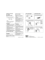
REMOVE GROUND STRAP AND DISCARD
KEEP GREEN GROUND SCREW
RELOCATE GREEN GROUND
SCREW HERE
strain relief
bracket
HOT
NEUTRAL
(white)
3/4", UL
recognized
strain relief
HOT
Remove the cover near the power cord entry hole.
Install 3/4" UL recognized strain relief to power
cord entry hole. Bring power cord through strain
relief.
Connect two HOT lines to outer screws (L1 & L2)
of terminal block.
Connect NEUTRAL (white) line to center screw (N)
of terminal block.
Attach ground wire of the power cord with the
green ground screw (hole above strain relief bracket).
Tighten all terminal block screws firmly.
Properly secure power supply cable to strain relief.
Reinstall the cover.
CONNECTING DRYER USING 4-WIRE CONNECTION
REAR EXHAUST LOCATION
The dryers come ready for rear exhausting. Units
have separate exhausts.
EXHAUST LENGTH
EXHAUST INFORMATION
MAXIMUM LENGTH
EXHAUST
HOOD TYPE
A B
NUMBER
OF 90˚
TURNS
RIGID METAL DUCT 0 45 ft. 30 ft.
35 ft. 20 ft.
4" DIAMETER 2 25 ft. 10 ft.
PARTS AVAILABLE FROM LOCAL SERVICE
ORGANIZATION
Rigid Metal Duct Components
WX8X63 4" X 1' Duct
WX8X64 4" x 2' Duct
WX8X51 4" Elbow
WX8X59 4" Aluminum Hood
Flexible Metal Duct Components
WX08X10077 4" dia. flexible metal (semi-rigid)
UL-listed transition duct (includes 2 elbows)
CAUTION: For personal safety this appliance
must be properly grounded.
WARNING :
Never leave the terminal block without the cover.
WARNING: Only a 4-conductor cord shall be used when the
appliance is installed in a location where grounding through the
neutral conductor is prohibited. Grounding through the neutral is
prohibited for the new branch-circuit installations, mobile homes,
recreational vehicles, and areas where local codes prohibit
grounding through the neutral conduction.
The MAXIMUM ALLOWABLE duct length and number of
bends of the exhaust system depends upon the type of duct,
number of turns, the type of exhaust hood (wall cap), and all
conditions note below. The maximum allowable length for
rigid metal duct is shown in the
table below. More than two 90˚
turns is not recommended. The
total length of flexible metal duct
shall not exceed 8 ft.(2.4 m). In
Canada and in the United States,
the required exhaust duct diameter
is 4in (102mm).
WARNING - TO REDUCE THE RISK OF
FIRE OR PERSONAL INJURY:
Provide an access for inspection and cleaning of the
exhaust system, especially at turns and joints.
Exhaust system shall be inspected and cleaned at
least once a year.
Do not obstruct incoming or exhausted air.
Do not assemble ductwork with any fasteners that
extend into the duct. These fasteners can accumul-
ate lint, creating a potential fire hazard.
In special installations, it may be necessary to connect
the dryer to the house vent using a flexible metal (foil-
type) duct. A UL-listed flexible metal (foil-type) duct
may be used ONLY in installations where rigid metal or
flexible metal (semi-rigid) ducting cannot be used AND
where a 4” diameter can be maintained throughout the
entire length of the transition duct. In Canada and in
the United States, only the flexible metal (foil-type)
ducts that comply with the “Outline for Clothes Dryer
Transition Duct Subject 2158A” shall be used.
Never install a screen in or over the exhaust duct.
This will cause lint to accumulate, creating a poten-
tial fire hazard.
Do not use duct longer than specified in the exhaust
length table. Longer ducts can accumulate lint,
creating a potential fire hazard.
Never terminate the exhaust into a common duct
with a kitchen exhaust system. A combination of
grease and lint creates a potential fire hazard.
Do not terminate exhaust in a chimney, a wall, a ceil-
ing, gas vent, crawl space, attic, under an enclosed
floor, or in any other concealed space of a building.
The accumulated lint could create a fire hazard.
Use only 4” rigid metal or UL-listed flexible metal
(semi-rigid or foil-type) duct to connect the dryer to
the home exhaust duct. It must be installed in
accordance with these instructions and local codes.
Use only 4” rigid metal ducting for the home exhaust
duct.
This clothes dryer must be exhausted to the outdoors.
4 #10 AWG MINIMUM COPPER CONDUCTORS OR 120/240V 30A
POWER SUPPLY CORD KIT MARKED FOR USE WITH DRYERS &
PROVIDED WITH CLOSED LOOP OR SPADE TERMINALS WITH
UPTURNED ENDS (NOT SUPPLIED).
Detach and remove the desired knockout.
Remove the screw inside the dryer exhaust duct end.
Keep the screw for step 5. Pull on the duct to remove it.
Cut the duct as shown. Keep portion A.
Through the rear opening, locate the tab in the middle of
the dryer base. Lift the tab to about 45˚ using a flat
screwdriver.
Reconnect and secure the cut portion (A) of the duct to
the blower housing. Make sure that the fixing hole is
aligned with the tab in the base. Use the screw of item 2
to secure the duct in place through the tab on the dryer
base.
Use standard metal elbows and duct to complete
exhaust system. Insert standard elbow and ducts
through rear and side or bottom openings.
Cover the opening at the back with the plate (Kit
WE1M454) available from your Local Service Provider.
SIDE OR BOTTOM EXHAUST
STEPS TO CHANGE DRYER TO SIDE OR BOTTOM EXHAUST DIRECTLY ON CABINET
NOTE: Protect your hands and arms from sharp edges when working inside dryer cabinet.
Minimum clearances are 0" both sides
1" at rear
88" vertical space from floor to ceiling
MINIMUM CLEARANCES
EXHAUST SYSTEM CHECK LIST
HOOD OR WALL CAP
Terminate in a manner to prevent back drafts or
entry of birds or other wildlife.
Termination should present minimal resistance to the
exhaust air flow and should require little or no
maintenance to prevent clogging.
Wall caps must be installed at least 12" above
ground level or any other obstruction with the
opening pointed down.
SEPARATION OF TURNS
Separate all turns by at least 3 ft. of straight duct,
including distance between last turn and dampered
wall cap. If two turns must be closer than 3 ft., deduct
10 ft. from the maximum lengths shown in the table for
each occurrence.
TURNS OTHER THAN 90˚
One turn of 45˚ or less may be ignored.
Two 45˚ turns should be treated as one 90˚.
Each turn over 45˚ should be treated as one 90˚.
SEALING OF JOINTS
All joints should be tight to avoid leaks. The mal
e
end of each section of duct must point away from
the dryer.
Do not assemble the duct work with fasteners that
extend into the duct. They will serve as a collection
point for lint.
Duct joints can be made air and moisture-tight by
wrapping the overlapped joints with duct tape.
INSULATION
Duct work which runs through an unheated area or is
near an air conditioning duct should be insulated to
reduce condensation and lint build up and be sloped
down toward outdoors.
NOTE: Never install screen inside exhaust duct.
EXHAUST INFORMATION (continued)
Note to Installer:
After Installation check the following:
Exhaust Duct - must meet specs as mentioned in
“Exhaust Information section of this installation
instructions.
Grounding - Dryer must be properly grounded to
conform to local codes and ordinance
requirements.
Operation - Turn dryer ON and check for heat.
Hand Customer the Use and Care Book - Give
instructions on operating the dryer - answer any
questions.
Give these Installation Instructions to the customer.
WARNING: NEVER LEAVE THE BACK OPENING WITHOUT THE PLATE.
  • Page 1 1
  • Page 2 2
  • Page 3 3
  • Page 4 4

GE DDC4400SWH Installation guide

Type
Installation guide
This manual is also suitable for

GE DDC4400SWH is a commercial stacked electric dryer with advanced features for efficient laundry care. It offers a large capacity, allowing you to dry multiple loads of laundry at once. The dryer is equipped with a variety of drying cycles, including timed dry, sensor dry, and wrinkle care, providing flexibility for different fabric types and drying needs. Additionally, the dryer features a moisture sensor that automatically adjusts the drying time based on the moisture level of the clothes, preventing over-drying and ensuring energy efficiency.

Ask a question and I''ll find the answer in the document

Finding information in a document is now easier with AI