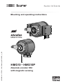
Baumer HMG10P-T - SSI Assembly Instruction
- Category
- Measuring, testing & control
- Type
- Assembly Instruction
This manual is also suitable for

HMG10 • HMG10P
Absolute encoder SSI
with magnetic sensing
Mounting and operating instructions
MB244EN - 11171691, 19A2, Baumer_HMG10-SSI_II_EN

TABLE OF CONTENTS
MB244EN - 11171691, 19A2, Baumer_HMG10-SSI_II_EN
TABLE OF CONTENTS
1. IMPORTANT NOTES .............................................................................................................1
1.1 Symbol guide ..................................................................................................................1
1.2 Intended use ...................................................................................................................1
1.3 Exclusion from liability ....................................................................................................1
1.4 Maintenance and service life ..........................................................................................2
1.5 Approvals and warranty ..................................................................................................2
1.6 Operating and storage temperature range .....................................................................2
1.7 Disposal (environmental protection) ...............................................................................2
2. SAFETY AND ATTENTION INSTRUCTIONS ........................................................................ 3
2.1 Safety instructions .........................................................................................................3
2.2 Attention instructions for mounting and operation ..........................................................4
3. PREPARATION ......................................................................................................................5
3.1 Scope of delivery ............................................................................................................5
3.2 Required accessories for mounting/dismounting (not included in scope of delivery) .....6
3.3 Required tools (not included in scope of delivery) ..........................................................6
4. MOUNTING ............................................................................................................................7
4.1 Positioning the support plate ..........................................................................................7
4.2 Mounting the torque arm at the device ...........................................................................7
4.3 Mounting to drive shaft ...................................................................................................8
4.3.1 Blind hollow shaft .................................................................................................8
4.3.2 Cone shaft ............................................................................................................9
4.3.3 Through hollow shaft ..........................................................................................10
4.4 Drive side mounting of the torque arm .........................................................................11
4.5 How to prevent measurement errors ............................................................................12

TABLE OF CONTENTS
MB244EN - 11171691, 19A2, Baumer_HMG10-SSI_II_EN
5. ELECTRICAL CONNECTION ..............................................................................................13
5.1 Terminalsignicance ....................................................................................................13
5.2 SSI interface .................................................................................................................14
5.2.1 Data transfer ....................................................................................................... 14
5.2.2 Function „RESET“ ..............................................................................................14
5.2.3 Function „Rotating direction“ ..............................................................................14
5.3 Additional output incremental (option) ..........................................................................15
5.3.1 Output signals ....................................................................................................15
5.3.2 Trigger level ........................................................................................................15
5.4 Programming interface (only HMG10P) .......................................................................16
5.5 LED function displays ...................................................................................................16
5.6 Switching characteristics speed switch (option) ...........................................................17
5.7 Electrical connection with radial terminal boxes ...........................................................18
5.7.1 Cable connection ................................................................................................ 18
5.7.2 Assignment connecting terminal ........................................................................19
5.7.2.1 Connectingterminalrstterminalbox[A] .............................................19
5.7.2.2 Connectingterminalsecondterminalbox[B] .......................................19
5.8 Electricalconnectionwithradialangeconnectors ......................................................20
5.8.1 Cable connection mating connector M23 (accessory) .......................................20
5.8.2 Assignmentangeconnectors ...........................................................................21
5.8.2.1 Firstangeconnector[C] ......................................................................21
5.8.2.2 Secondangeconnector[D] ................................................................21
6. ACCESSORIES ...................................................................................................................22
6.1 Z-PA.SDL.1 WLAN adapter: Programming device for HMG10P ..................................22
6.2 Sensor cable and mating connector .............................................................................23
6.2.1 Sensor cable ......................................................................................................23
6.2.2 Mating connector M23 ........................................................................................23
6.2.3 Mating connector M23, 17-pin with sensor cable HEK 17 .................................. 24
6.2.3.1 For version without additional output incremental ................................24
6.2.3.2 For version with additional output incremental .....................................25

TABLE OF CONTENTS
MB244EN - 11171691, 19A2, Baumer_HMG10-SSI_II_EN
7. DIMENSIONS .......................................................................................................................26
7.1 Blind hollow shaft .......................................................................................................... 26
7.1.1 With radial terminal boxes ..................................................................................26
7.1.2 Withradialangeconnectors .............................................................................26
7.2 Through hollow shaft ....................................................................................................27
7.2.1 With radial terminal boxes ..................................................................................27
7.2.2 Withradialangeconnectors .............................................................................27
7.3 Cone shaft ....................................................................................................................28
7.3.1 With radial terminal boxes ..................................................................................28
7.3.2 Withradialangeconnectors .............................................................................28
8. DISMOUNTING ....................................................................................................................29
8.1 Blind hollow shaft or cone shaft ....................................................................................29
8.1.1 Step 1 .................................................................................................................29
8.1.2 Step 2 .................................................................................................................29
8.1.3 Step 3 .................................................................................................................30
8.1.4 Step 4 .................................................................................................................30
8.2 Through hollow shaft ....................................................................................................31
9. TECHNICAL DATA ..............................................................................................................32
9.1 Technical data - electrical ratings .................................................................................32
9.2 Technical data - electrical ratings (speed switch) .........................................................32
9.3 Technical data - mechanical design .............................................................................. 33

IMPORTANT NOTES
MB244EN - 11171691, 19A2, Baumer_HMG10-SSI_II_EN 1/35
1. IMPORTANT NOTES
1.1 Symbol guide
Warning
Disregarding could result in serious injury, death or damage to property
)
Attention
Disregarding could result in damage to property or damage/malfunction of the device
i
Information
Additional information and recommendations
1.2 Intended use
The encoder HMG10/HMG10P is a precision measurement device for the acquisition of
speed/position information for the control of drive units and the provision of electronic out-
put signals for downstream devices.
The device must not be used for any other purpose. The function of the device is descri-
bed in this mounting instruction. The customer must check the suitability for the purpose
intended.
Mountingandselectionmustbeexecutedbyauthorizedandqualiedpersonnel.Moun-
ting, electrical commissioning or any other work with the device or system is to be perfor-
medbyappropriatelyqualiedstaffonly.
Do not put the device into service if there is any visible evidence of damage.
Do not operate the device beyond the limit values stated in this mounting instruction.
Any risk of personal injury, damage of the system or company equipment due to failure or
malfunction of the device must be eliminated by corresponding safety measures.
Warning
Disregarding intended use could result in serious injury or damage to property.
1.3 Exclusion from liability
The manufacturer is not liable for any damage to persons or property resulting from unin-
tended use of the device.

IMPORTANT NOTES
2/35 MB244EN - 11171691, 19A2, Baumer_HMG10-SSI_II_EN
1.4 Maintenance and service life
The device may be only opened as described in this instruction. Repair or maintenance
work that requires opening the device completely must be carried out by the manufacturer.
Alterations of the device are not permitted.
The expected service life of the device depends on the ball bearings, which are equipped
with a permanent lubrication.
In the event of queries or subsequent deliveries, the data on the device type label must be
quoted, especially the type designation and the serial number.
1.5 Approvals and warranty
EU Declaration of Conformity meeting to the European Directives.
UL approval / E256710.
We grant a 2-year warranty in accordance with the regulations of the Central Association of
the German Electrical Industry (ZVEI).
i
warranty seal
Damaging the warranty seal on the device invalidates warranty.
1.6 Operating and storage temperature range
The storage temperature range of the device is between -15 °C and +70 °C (caused by
packing).
The operating temperature range of the device is between -40 °C and +95 °C (device with
speed switch with solid state relay: -40 °C and +85 °C), measured at the housing.
1.7 Disposal (environmental protection)
Do not dispose of electrical and electronic equipment in household waste. The
product contains valuable raw materials for recycling. Whenever possible, waste
electrical and electronic equipment should be disposed locally at the authorized
collection point. If necessary, Baumer gives customers the opportunity to dispose
of Baumer products professionally. For further information see www.baumer.com.

SAFETY AND ATTENTION INSTRUCTIONS
MB244EN - 11171691, 19A2, Baumer_HMG10-SSI_II_EN 3/35
2. SAFETY AND ATTENTION INSTRUCTIONS
2.1 Safety instructions
Explosion risk
Sparkformationcancauseareoranexplosion.
» Donotusethedeviceinareaswithexplosiveand/orhighlyinammablematerials.
Theymayexplodeand/orcatchrebypossiblesparkformation.
Risk of serious injuries due to rotating shafts
Hair and clothes may become tangled in rotating shafts. Touching the rotating parts
can cause extremely serious injuries.
» Before all work switch off all voltage supplies and ensure machinery is stationary.
» Prevent reconnection voltage supply by third parties.
Risk of serious injuries due to consequential damages
Plants can be deregulated due to malfunction or faulty signals of the device.
» Damage caused by faulty operation or by a malfunction of the device must be
eliminated by corresponding safety measures.
Risk of burns due to formation of heat
The device heats up at higher speed so there is a serious risk of burning shortly after
the machine has been turned off.
» Examine carefully whether the device overheats. Wear suitable gloves if neces-
sary.

SAFETY AND ATTENTION INSTRUCTIONS
4/35 MB244EN - 11171691, 19A2, Baumer_HMG10-SSI_II_EN
2.2 Attention instructions for mounting and operation
)
Risk of destruction due to electrostatic charge
Electronic parts contained in the device are sensitive to high voltages.
» Do not touch plug contacts or electronic components.
» Protect output terminals against external voltages.
» Do not exceed maximum voltage supply.
)
Risk of destruction due to mechanical overload
Rigid mounting may give rise to constraining forces.
» Never restrict the freedom of movement of the device. The mounting instructions
must be followed.
» Itisessentialthatthespeciedclearancesand/oranglesareobserved.
)
Risk of destruction due to mechanical shock
Violent shocks, e. g. due to hammer impacts, can lead to the destruction of the
sensing system.
» Never use force. Mounting is simple when correct procedure is followed.
» Use suitable puller for dismounting.
)
Risk of destruction due to contamination
Dirt penetrating inside the device can cause short circuits and damage the sensing
system.
» Absolute cleanliness must be maintained when carrying out any work on the
device.
» Never allow lubricants to penetrate the device.
)
Riskofdestructionduetoadhesiveuids
Adhesiveuidscandamagethesensingsystemandtheballbearings.Dismounting
a device, secured to a shaft by adhesive may lead to the destruction of the device.
» Donotuseadhesiveuidsforxing.

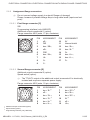
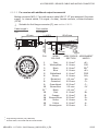
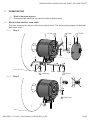
6d 6e 6f
1
7a 6a 6b
8c8b
8a
6c
7b
5
[B] [A]
7a 4
2
4
8a
32
[C][D]
PREPARATION
MB244EN - 11171691, 19A2, Baumer_HMG10-SSI_II_EN 5/35
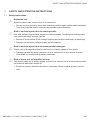
3. PREPARATION
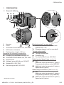
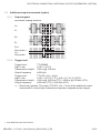
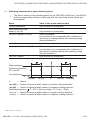
3.1 Scope of delivery
1 Housing
2 Cover
3 Torx/slotted screw M4x10 mm, DIN 7964
4 LED function indicators
5 Earthing strap, length ~230 mm
Equipment for mounting a torque arm:
6a Clamping ring adjustable through 360°
6b Torx/slotted screw M4x20 mm, ISO 7045
6c Support plate
6d Hexagon screw M6x18 mm, ISO 4017
6e Washer B6.4, ISO 7090
6f Self-locking nut M6, ISO 10511
Blind hollow shaft* or cone shaft*:
7a Blind hollow shaft or cone shaft with
spannerat17a/f
7b Clamping element, not for cone shaft
Through hollow shaft*:
8a Through hollow shaft
8b Clamping ring
8c Torx screw M3x12 mm, ISO 7045
Radial terminal boxes* (see section 5):
[A] SSI
Additional output incremental 1 (option)
Programming interface (only HMG10P)
[B] Additional output incremental 2 (option)
Speed switch (option)
Radialangeconnectors*(seesection 5):
[C] SSI
Additional output incremental 1 (option)
Programming interface (only HMG10P)
[D] Additional output incremental 2 (option)
Speed switch (option)
* Depending on version

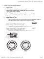
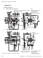
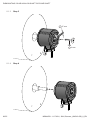
9
10a 10b 10c
10e 10d
11a
11d
11b
11c
PREPARATION
6/35 MB244EN - 11171691, 19A2, Baumer_HMG10-SSI_II_EN
3.2 Required accessories for mounting/dismounting (not included in scope of delivery)
i
Connecting cables and respective mating connectors are required for the electrical
connection. Details see section 6.2, page 23.
Torque arm, length L / order number
9 Standard:
67...70 mm / 11043628
125(±5)mm,canbeshortenedto≥71mm/11004078
440(+20/-15)mm,canbeshortenedto≥131mm/11002915
9 Insulated:
67...70 mm / 11054917
125(±5)mm,canbeshortenedto≥71mm/11072795
440(+20/-15)mm,canbeshortenedto≥131mm/11082677
Mounting kit, order number 11077197:
10a ThreadrodM6,lengthvariable≤210mm
10b Washer B6.4, ISO 7090
10c Self-locking nut M6, ISO 10511
10d Cylinder screw M6x8 mm for earthing strap, ISO 1207
10e Washer B6.4 for earthing strap, ISO 7090
Mounting/dismounting kit, order number 11077087:
(Not required for through hollow shaft)
11a Cylinder screw M6x30 mm, ISO 4762
11b Spring washer 6, DIN 7980
11c Setscrew M6x10 mm, ISO 7436
11d Cylinder screw M8x45 mm, ISO 4762
L
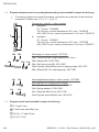
3.3 Required tools (not included in scope of delivery)
3, 5 and 6 mm
1.6x8.0 mm and 0.8x4 mm
10 (2x), 17 and 22 mm
TX 10, TX 20

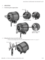
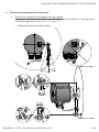
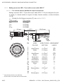
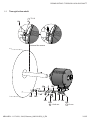
6a6b
6e
6c
6f96d
MOUNTING / POSITIONING THE SUPPORT PLATE
MB244EN - 11171691, 19A2, Baumer_HMG10-SSI_II_EN 7/35
4. MOUNTING
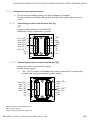
4.1 Positioning the support plate
4.2 Mounting the torque arm at the device
» Note the mounting instructions for the torque arm in section 4.4, page 11.
360°
10 mm
Loosen the screw
Tighten the screw
M
t
= 2...3 Nm
TX 20
10 mm

DIN 332-D
M6x16 mm
16 mm
≥ ød + 4 mm
L1
L2
ød
ød (mm) L1 (mm) L2 (mm)
16
h6
53 52 (40...52)
20
h6
35 34 (25...34)
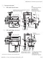
10c10b 10a 5
10e
10d
10c
10b
10b
10c9
7b
11b 11a
7a 32
M
t
= 6 Nm
TX 2017 mm
5 mm
10 mm1.6x8 mm
7b
MOUNTING / MOUNTING TO DRIVE SHAFT
8/35 MB244EN - 11171691, 19A2, Baumer_HMG10-SSI_II_EN
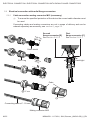
4.3 Mounting to drive shaft
4.3.1 Blind hollow shaft
)
Service life restrictions and angle error by runouts
High runout of the drive shaft can cause device angle error, see section 4.5,
page 12.
High runout of the drive shaft can cause vibrations, which can shorten the ser-
vice life of the device.
» Lubricate drive shaft!
» Minimizedriveshaftrunout(≤0.2mm;≤0.03mmrecommended).
i
The device must be mounted with cable connection facing downward and not
exposed to water.

10c10b 10a 5
10e
10d
10c
10b
10b
10c9
11b 11a
7a 32
M
t
= 3...4 Nm
TX 2017 mm
5 mm
10 mm1.6x8 mm
MOUNTING / MOUNTING TO DRIVE SHAFT
MB244EN - 11171691, 19A2, Baumer_HMG10-SSI_II_EN 9/35
4.3.2 Cone shaft
)
Service life restrictions and angle error by runouts
High runout of the drive shaft can cause device angle error, see section 4.5,
page 12.
High runout of the drive shaft can cause vibrations, which can shorten the ser-
vice life of the device.
» Lubricate drive shaft!
» Minimizedriveshaftrunout(≤0.2mm;≤0.03mmrecommended).
i
The device must be mounted with cable connection facing downward and not
exposed to water.

≥ ød
>113 mm
ød
ød (mm)
16
h6
20
h6
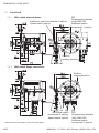
10c10b
10a 5 10c
10e
10d
10b 10b
10c
9
8c8b
MOUNTING / MOUNTING TO DRIVE SHAFT
10/35 MB244EN - 11171691, 19A2, Baumer_HMG10-SSI_II_EN
4.3.3 Through hollow shaft
)
Service life restrictions and angle error by runouts
High runout of the drive shaft can cause device angle error, see section 4.5,
page 12.
High runout of the drive shaft can cause vibrations, which can shorten the ser-
vice life of the device.
» Lubricate drive shaft!
» Minimizedriveshaftrunout(≤0.2mm;≤0.03mmrecommended).
i
The device must be mounted with cable connection facing downward and not
exposed to water.
Loosen the screw
Tighten the screw
M
t
= 2...3 Nm
TX 10
1.6x8 mm 10 mm

MOUNTING / DRIVE SIDE MOUNTING OF THE TORQUE ARM
MB244EN - 11171691, 19A2, Baumer_HMG10-SSI_II_EN 11/35
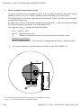
4.4 Drive side mounting of the torque arm
)
Service life restrictions and angle error by runouts
A play of just ±0.03 mm, results in a runout of the device of 0.06 mm. That may lead
to a large angle error, see section 4.5, page 12.
» Mount the torque arm without play.
9°
9°
9°
9°
15°
15°

MOUNTING / HOW TO PREVENT MEASUREMENT ERRORS
12/35 MB244EN - 11171691, 19A2, Baumer_HMG10-SSI_II_EN
4.5 How to prevent measurement errors
To ensure that the device operates correctly, it is necessary to mount it accurately as de-
scribed in section 4.1 to 4.4, which includes correct mounting of the torque arm.
The radial runout of the drive shaft should not exceed 0.2 mm (0.03 mm recommended),
to prevent an angle error.
An angle error may be reduced by increasing the length of L1
1)
. Make sure that the length
L2 of the torque arm, see below, is at least equal to L1
2)
.
TheangleerrorΔρ
mech
can be calculated as follows:
Δρ
mech
=±90°/π·R/L1
with R: Radial runout in mm
L1: Distance of the torque arm to the center point of the device in mm
Example of calculation:
ForR=0.06mmandL1=69.5mmtheresultingangleerrorΔρ
mech
equals ±0.025°.
i
For more information, call the telephone hotline at +49 (0)30 69003-111
L1
L2 (≥L1)
1) For this different support plates for the torque arm are available on request.
2) If L2 < L1, L2 must be used in the calculation formula.

ELECTRICAL CONNECTION / TERMINAL SIGNIFICANCE
MB244EN - 11171691, 19A2, Baumer_HMG10-SSI_II_EN 13/35
5. ELECTRICAL CONNECTION
5.1 Terminal signicance
Ub Voltage supply
0V Ground
A+
3)
Output signal channel 1
A−
3)
Output signal channel 1 inverted
B+
3)
Output signal channel 2 (offset by 90° to channel 1)
B−
3)
Output signal channel 2 inverted
R+
3)
Zero pulse (reference signal)
R−
3)
Zero pulse inverted
nE+ System OK+ / error output
nE− SystemOK−/erroroutputinverted
PRE RESET (see also section 5.2.2)
DIR Rotating direction (see also section 5.2.3)
SP+
4)
DSL_OUT1 / speed switch (open collector* or solid state relay*)
SP−
4)
DSL_OUT2 / speed switch (0V* or solid state relay*)
SA
5)
RS485+ / programming interface
SB
5)
RS485−/programminginterface
D+ SSI data+
D− SSIdata−
C+ SSI clock+
C− SSIclock−
dnu Do not use
* Depending on version
3) Additional output incremental (option)
4) Speed switch (option)
5) Programming interface (only HMG10P)

ELECTRICAL CONNECTION / SSI INTERFACE
14/35 MB244EN - 11171691, 19A2, Baumer_HMG10-SSI_II_EN
5.2 SSI interface
5.2.1 Data transfer
msb → lsbmsb → lsb
Clock
Data
n-1...0 bit
m-1...0 bit
Position Speed
t
Clock frequency 100 kHz...2 MHz
Monooptime(t) 20µs(internal)
n, m Number of bits
i
For continous clocking, the SSI word is transmitted only once followed by zero
values (no ring register operation).
5.2.2 Function „RESET“
With the function „RESET“ (RESET input) the position value of the SSI signal is set to
0 (factory setting, other values are possible on request).
» A voltage of 4...30 VDC must be applied to the RESET input for more than 100
ms to set the current position to 0.
i
TheRESETinputhasnoinuenceontheincrementalsignals.
TheRESETinputhasnoinuenceonthespeedswitch.
i
If a voltage of 4...30 VDC is applied to the RESET input during the initialization
phase after switching on, the delay time of 100 ms does not begin until after the
initialization phase.
5.2.3 Function „Rotating direction“
The function „rotating direction“ (DIR input) reverses the rotating direction of the SSI
signal.
» A voltage of 4...30 VDC must be applied to the DIR input for more than 100 ms
to reverse the current rotating direction of the SSI signal. For the duration of
the applied voltage of 4...30 VDC, the rotating direction of the SSI signal is then
reversed.
i
TheDIRinputhasnoinuenceontheincrementalsignals.
TheDIRinputhasnoinuenceonthespeedswitch.

ELECTRICAL CONNECTION / ADDITIONAL OUTPUT INCREMENTAL (OPTION)
MB244EN - 11171691, 19A2, Baumer_HMG10-SSI_II_EN 15/35
5.3 Additional output incremental (option)
5.3.1 Output signals
90°
A
+
A
-
B+
B-
R+
Zero pulse+
R-
Zero pulse-
At positive rotating direction
6)
6)
5.3.2 Trigger level
Trigger level: TTL/RS422
High/Low: ≥2.5V/≤0.5V
Transmissionlength: ≤550m@100kHz
Outputfrequency ≤600kHz
Trigger level: TTL/HTL (Vin = Vout)
High/Low: ≥2.5V/≤0.5V(TTL)ǀ≥Ub-3V/≤1.5V(HTL)
Transmissionlength: ≤550m@100kHz(TTL)ǀ≤350m@100kHz(HTL)
Outputfrequency ≤600kHz(TTL)ǀ≤350kHz(HTL)
)
Electrically isolated: The output TTL/HTL (Vin = Vout) at the additional output
incremental 2 is electrically isolated and requires a separate power supply.
6) Only additional output incremental 2

ELECTRICAL CONNECTION / PROGRAMMING INTERFACE (ONLY HMG10P)
16/35 MB244EN - 11171691, 19A2, Baumer_HMG10-SSI_II_EN
5.4 Programming interface (only HMG10P)
Encoder parameter like resolution singleturn and/or multiturn (SSI), binary or gray code
(SSI), additional output 1 and 2, switch-off and switch-on speeds can get and set via SA
and SB. With the Z-PA.SDL.1 WLAN adapter, available as accessory, see section 6.1, it is
possible to get access to the encoder via webbrowser.
5.5 LED function displays
LED red green
INC1 (additional output Undervoltage, overload, OK
incremental 1) over-temperature
INC2 (additional output Undervoltage, overload, OK
incremental 2) over-temperature
Status Internal error OK
Speed Speed higher Speed lower
switching speed (overspeed) switching speed
Page is loading ...
Page is loading ...
Page is loading ...
Page is loading ...
Page is loading ...
Page is loading ...
Page is loading ...
Page is loading ...
Page is loading ...
Page is loading ...
Page is loading ...
Page is loading ...
Page is loading ...
Page is loading ...
Page is loading ...
Page is loading ...
Page is loading ...
Page is loading ...
Page is loading ...
Page is loading ...
-
 1
1
-
 2
2
-
 3
3
-
 4
4
-
 5
5
-
 6
6
-
 7
7
-
 8
8
-
 9
9
-
 10
10
-
 11
11
-
 12
12
-
 13
13
-
 14
14
-
 15
15
-
 16
16
-
 17
17
-
 18
18
-
 19
19
-
 20
20
-
 21
21
-
 22
22
-
 23
23
-
 24
24
-
 25
25
-
 26
26
-
 27
27
-
 28
28
-
 29
29
-
 30
30
-
 31
31
-
 32
32
-
 33
33
-
 34
34
-
 35
35
-
 36
36
-
 37
37
-
 38
38
-
 39
39
-
 40
40


Baumer HMG10P-T - SSI Assembly Instruction
- Category
- Measuring, testing & control
- Type
- Assembly Instruction
- This manual is also suitable for
Ask a question and I''ll find the answer in the document
Finding information in a document is now easier with AI
Related papers
-
Baumer HMG10P-T PROFINET Assembly Instruction
-
-
-
Baumer HMG10P-B - Profibus DP Assembly Instruction
-
-
-
-
-
-
Baumer DLM40-SO Installation and Operating Instructions
Other documents
-
SICK DFS60 Incremental Encoders Product information
-
Siemens SE28280EU/07 Owner's manual
-
-
-
Siemens SRU4660/01 User manual
-
-
BENDIX TCH-005-004 User manual
-
-
-
Pepperl+Fuchs K23-SSI/USB/25B-C Owner's manual