Page is loading ...

PRODUCT INFORMATION
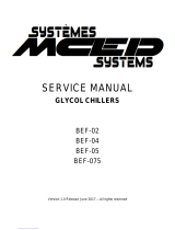
AFS/AFM60 INOX
RESISTANT, PRECISE, PROGRAMMABLE
Absolute encoders

ENCODERS AND INCLINATION SENSORS | SICK 8020315/2016-09-14
Subject to change without notice
2
AFS/AFM60 Inox ABSOLUTE ENCODERS
Product description
With a high resolution of 18 bits (AFS60
Inox) or 30 bits (AFM60 Inox) and a large
selection of programmable parameters,
the AFS60 Inox absolute singleturn en-
coder and the AFM60 Inox absolute mul-
titurn encoder set new standards when
it comes to stainless-steel encoders.
The high resolution, the high IP enclo-
sure rating, and the stainless-steel
housing enable use in applications
under harsh ambient conditions. The
encoders are equipped with the SSI
interface while the AFM60 Inox is also
available with the SSI + Incremental
and SSI + Sin/Cos combined interfaces.
Both encoders can be programmed
using the PC-based programming device
PGT-08-S or the hand-held programming
device PGT-10-Pro.
At a glance
• Housing, ange, and shaft made from
stainless steel
• Face mount, servo, or square ange
with solid shaft and blind hollow shaft
• Enclosure rating: IP 67
• Resolution: up to 262,144 steps per
revolution and 4,096 revolutions
• Electrical interfaces: SSI, SSI + Incre-
mental, SSI + Sin/Cos
• Can be optionally programmed with
PGT-08-S and PGT-10-Pro
Your benets
• High resistance to environmental
inuences due to stainless-steel
housing
• IP 67 enclosure rating and shaft seal-
ing ring for optimum tightness
• High singleturn resolution up to
18 bits (AFS60 Inox) enables use in
applications with demanding require-
ments for measurement accuracy
• The wide range of mechanical
interfaces allows an optimal match
between the encoder and the appli-
cation-specic installation situation
• Simple mounting thanks to compact
dimensions, even in conned spaces
• Reduces storage costs and down-
times since customers can pro-
gram the encoder themselves with
programming devices PGT-08-S and
PGT-10-Pro
Encoders and inclination sensors
ABSOLUTE ENCODERS
AFS/AFM60 Inox
Subject to change without notice
G
.
RESISTANT, PRECISE, PROGRAMMABLE
Additional information
Fields of application. . . . . . . . . . . . . . .3
Detailed technical data . . . . . . . . . . . .3
Type code . . . . . . . . . . . . . . . . . . . . . . .6
Ordering information . . . . . . . . . . . . . .8
Dimensional drawings . . . . . . . . . . . .10
Maximum revolution range . . . . . . . 12
PIN assignment. . . . . . . . . . . . . . . . . 12
Signal outputs. . . . . . . . . . . . . . . . . . 14
Interfaces . . . . . . . . . . . . . . . . . . . . . 15
Accessories. . . . . . . . . . . . . . . . . . . . .16
- www.sick.com/AFS_AFM60_Inox
For more information, simply enter the link or scan the QR code and get direct access to techni-
cal data, CAD design models, operating instructions, software, application examples, and much
more.
A
B
C
D
E
F
H
I
J
K
L
M
N
O
P
Q
R
S
T

ENCODERS AND INCLINATION SENSORS | SICK8020315/2016-09-14
Subject to change without notice
3
ABSOLUTE ENCODERS AFS/AFM60 Inox
Fields of application
• Applications with high resistance requirements against ag-
gressive substances such as cleaning agents or salt
• Particularly suitable for use in the food and drink industry,
for packaging machines, in medical technology, and in
outdoor applications in ports or offshore plants
Detailed technical data
Performance
Max. number of steps per revolution
262,144 (SSI-Interface)
1)
Max. number of revolutions
Singleturn 1
Multiturn 4,096
Resolution
18 bit x 1 bit
18 bit x 12 bit
Error limits
± 0.03°
Repeat accuracy
≤ 0.002°
Initialization time
50 ms
2)
Position forming time
< 1 µs
1)
See maximum viewing number of resolutions.
2)
Valid positional data can be read once this time has elapsed.
Interfaces
SSI
Electrical interface
SSI/Gray
SSI/Gray, programmable
Code type
Gray
Code sequence parameter adjustable
CW/CCW
Measuring step
360° / number of steps 0.0 014°
Clock frequency
2 MHz
1)
Set (electronic adjustment)
H-active (L ≡ 0 - 3 V, H ≡ 4.0 - Us V)
CW/CCW (counting sequence when turn-
ing)
L-active (L ≡ 0 - 1,5 V, H ≡ 2,0 - Us V)
Measuring step deviation (Range of pulses
per revolution)
1 … 399
400 … 40,000
> 40,000
± 0.04°
± 0.008°
± 0.002°
Interface signals
Clock +, Clock -, Data +, Data-
Signal offset
2.5 V ± 10 %
1)
SSI max. clock frequency 2 MHz, and min. LOW level (Clock+): 500 ns.
SSI + incremental
Electrical interface
SSI/Gray + Incremental, HTL
SSI/Gray + Incremental, TTL
SSI/Gray + Incremental, TTL/HTL, programmable
Code type
Gray
Code sequence parameter adjustable
CW/CCW
Measuring step
90° electronically / number of lines 0.0014°
1)
SSI max. clock frequency 2 MHz, and min. LOW level (Clock+): 500 ns.
A
B
C
D
E
F
H
I
J
K
L
M
N
O
P
Q
R
S
T

ENCODERS AND INCLINATION SENSORS | SICK 8020315/2016-09-14
Subject to change without notice
4
AFS/AFM60 Inox ABSOLUTE ENCODERS
Clock frequency
2 MHz
1)
Set (electronic adjustment)
H-active (L ≡ 0 - 3 V, H ≡ 4.0 - Us V)
CW/CCW (counting sequence when turn-
ing)
L-active (L ≡ 0 - 1,5 V, H ≡ 2,0 - Us V)
Measuring step deviation (Range of pulses
per revolution)
1 … 99
100 … 10,000
> 10,000
± 0.04°
± 0.008°
± 0.002°
Pulses per revolution
1/4 of number of SSI steps per revolution
Interface signals
A, A/, B, B/: digital differential
Maximum output frequency
≤ 820 kHz
Maximum load current
≤ 30 mA
Signal offset
2.5 V ± 10 %
1)
SSI max. clock frequency 2 MHz, and min. LOW level (Clock+): 500 ns.
SSI + Sin/Cos
Electrical interface
SSI/Gray + Sin/Cos, 1.024 periods
SSI/Gray + Sin/Cos, 1.024 periods, programmable
Code type
Gray
Code sequence parameter adjustable
CW/CCW
Measuring step
360° / number of steps 0.0 014°
Clock frequency
2 MHz
1)
Set (electronic adjustment)
H-active (L ≡ 0 - 3 V, H ≡ 4.0 - Us V)
CW/CCW (counting sequence when turn-
ing)
L-active (L ≡ 0 - 1,5 V, H ≡ 2,0 - Us V)
Measuring step deviation (Range of pulses
per revolution)
1 … 399
400 … 40,000
> 40,000
± 0.04°
± 0.008°
± 0.002°
Pulses per revolution
1,024
Min. load resistance
≥ 120 Ω
Interface signals
Sin +, Sin -, Cos + , Cos -: analog, differential
Maximum output frequency
≤ 200 kHz
Signal before differential generation
0.5 V
pp
, ± 20 %, 120 Ω
Signal offset
2.5 V ± 10 %
Signal after differential generation
1 V
pp
, ± 20 %, 120 Ω
1)
SSI max. clock frequency 2 MHz, and min. LOW level (Clock+): 500 ns.
A
B
C
D
E
F
H
I
J
K
L
M
N
O
P
Q
R
S
T

ENCODERS AND INCLINATION SENSORS | SICK8020315/2016-09-14
Subject to change without notice
5
ABSOLUTE ENCODERS AFS/AFM60 Inox
Electrical data
Connection type
Male connector M12, 8-pin, radial
Cable, 8-wire, radial, 1.5 m
Cable, 8-wire, radial, 3 m
Cable, 8-wire, radial, 5 m
Connector M12, 12-pin, radial
Cable, 12-wire, radial, 1.5 m
Cable, 12-wire, radial, 3 m
Cable, 12-wire, radial, 5 m
Operating voltage range
4.5 V DC ... 32 V DC
Power consumption max. without load
≤ 0.5 W
Reverse polarity protection
l
MTTFd: mean time to dangerous failure
250 years
1)
1)
This product is a standard product and does not constitute a safety component as dened in the Machinery Directive. Calculation based on nominal load of com-
ponents, average ambient temperature 40°C, frequency of use 8760 h/a. All electronic failures are considered hazardous. For more information, see document
no. 8015532.
Mechanical data
Shaft diameter
Solid shaft, Servo ange 6 mm x 10 mm
Solid shaft, Face mount ange 10 mm x 19 mm
Solid shaft, Square ange 10 mm x 19 mm
Blind hollow shaft 8 mm
3/8”
10 mm
12 mm
1/2”
14 mm
15 mm
5/8”
1)
Weight
0.5 kg
2)
Shaft material
Stainless steel
Flange material
Stainless steel
Housing material
Stainless steel
Start up torque
1 Ncm (+20 °C)
Operating torque
0.5 Ncm (+20 °C)
Permissible movement axial static/dy-
namic
Blind hollow shaft ± 0.5 mm, ± 0.1 mm
Permissible movement radial static/dy-
namic
Blind hollow shaft ± 0.3 mm, ± 0.1 mm
Permissible Load capacity of shaft
80 N / radial
40 N / axial
Moment of inertia of the rotor
Solid shaft 6.2 gcm²
Blind hollow shaft 40 gcm²
Bearing lifetime
3.0 x 10^9 revolutions
Max. angular acceleration
≤ 500,000 rad/s²
1)
5/8” not available for multiturn.
2)
For an encoder with connector outlet.
3)
Self warming of 3.3 K per 1000 revolutions/min when applying note working temperature range.
A
B
C
D
E
F
H
I
J
K
L
M
N
O
P
Q
R
S
T

ENCODERS AND INCLINATION SENSORS | SICK 8020315/2016-09-14
Subject to change without notice
6
AFS/AFM60 Inox ABSOLUTE ENCODERS
Operating speed
Solid shaft 9,000 /min
3)
Blind hollow shaft 6,000 /min
3)
1)
5/8” not available for multiturn.
2)
For an encoder with connector outlet.
3)
Self warming of 3.3 K per 1000 revolutions/min when applying note working temperature range.
Ambient data
EMC
According to EN 61000-6-2 and EN 61000-6-3
1)
Enclosure rating
IP 67, shaft side
IP 67, housing side, connector outlet
2)
IP 67, housing side, cable outlet
Permissible relative humidity
90 % (condensation of the optical scanning not permitted)
Working temperature range
–40 °C ... +100 °C
3)
–30 °C ... +100 °C
4)
Storage temperature range
–40 °C ... +100 °C, without package
Resistance to shocks
100 g, 6 ms (according to EN 60068-2-27)
Resistance to vibration
10 g, 10 Hz ... 2,000 Hz (according to EN 60068-2-6)
1)
EMC according to the standards quoted is achieved if shielded cables are used.
2)
With mating connector tted.
3)
Stationary position of the cable.
4)
Flexible position of the cable.
Type code
Multiturn, solid shaft
Mechanical design
S 1 Servo ange, 6 x 10 mm (via ange adaptor)
S 4 Face mount ange, 10 x 19 mm
Q 4 Square ange, 10 x 19 mm (via ange adaptor)
Electrical interface
A 4.5 … 32V, SSI, gray
P 4.5 … 32V, SSI, gray, programmable
L 4.5 … 32V, SSI, gray, Incremental HTL
T 4.5 … 32V, SSI, gray, Incremental TTL
R 4.5 … 32V, SSI, gray, Incremental programmable
K 4.5 … 32V, SSI, gray, Sin/Cos 1,024 periods
S 4.5 … 32V, SSI, gray, programmable, Sin/Cos 1.024 periods
Connection type
C Male connector M12, 8-pin oder 12-pin, radial
K Cable, 8-wire or 12-wire, radial 1.5 m
L Cable, 8-wire or 12-wire, radial 3 m
M Cable, 8-wire or 12-wire, radial 5 m
Resolution
Pulses per revolution
A F M 6 0 I -
A
B
C
D
E
F
H
I
J
K
L
M
N
O
P
Q
R
S
T

ENCODERS AND INCLINATION SENSORS | SICK8020315/2016-09-14
Subject to change without notice
7
ABSOLUTE ENCODERS AFS/AFM60 Inox
Singleturn, solid shaft
Mechanical design
S 1 Servo ange, 6 x 10 mm (via ange adaptor)
S 4 Face mount ange, 10 x 19 mm
Q 4 Square ange, 10 x 19 mm (via ange adaptor)
Electrical interface
A 4.5 … 32V, SSI, gray
P 4.5 … 32V, SSI, gray, programmable
Connection type
C Male connector M12, 8-pin, radial
K Cable, 8-wire, radial 1.5 m
L Cable, 8-wire, radial 3 m
M Cable, 8-wire, radial 5 m
Resolution
Pulses per revolution
A F S 6 0 I -
Multiturn, blind hollow shaft
Mechanical design
B Blind hollow shaft 8 mm
C Blind hollow shaft 3/8”
D Blind hollow shaft 10 mm
E Blind hollow shaft 12 mm
F Blind hollow shaft 1/2” mm
G Blind hollow shaft 14 mm
H Blind hollow shaft 15 mm
Electrical interface
A 4.5 … 32V, SSI, gray
P 4.5 … 32V, SSI, gray, programmable
L 4.5 … 32V, SSI, gray, Incremental HTL
T 4.5 … 32V, SSI, gray, Incremental TTL
R 4.5 … 32V, SSI, gray, Incremental programmable
K 4.5 … 32V, SSI, gray, Sin/Cos 1,024 periods
S 4.5 … 32V, SSI, gray, programmable, Sin/Cos 1,024 periods
Connection type
C Male connector M12, 8-pin or 12-pin radial
K Cable, 8-wire or 12-wire, radial 1.5 m
L Cable, 8-wire or 12-wire, radial 3 m
M Cable, 8-wire or 12-wire radial 5 m
Resolution
Pulses per revolution
A F M 6 0 I - B
A
B
C
D
E
F
H
I
J
K
L
M
N
O
P
Q
R
S
T

ENCODERS AND INCLINATION SENSORS | SICK 8020315/2016-09-14
Subject to change without notice
8
AFS/AFM60 Inox ABSOLUTE ENCODERS
Singleturn, blind hollow shaft
Mechanical design
B Blind hollow shaft 8 mm
C Blind hollow shaft 3/8”
D Blind hollow shaft 10 mm
E Blind hollow shaft 12 mm
F Blind hollow shaft 1/2” mm
G Blind hollow shaft 14 mm
H Blind hollow shaft 15 mm
J Blind hollow shaft 5/8”
Electrical interface
A 4.5 … 32V, SSI, gray
P 4.5 … 32V, SSI, gray, programmable
Connection type
C Male connector M12, 8-pin, radial
K Cable, 8-wire, radial 1.5 m
L Cable, 8-wire, radial 3 m
M Cable, 8-wire, radial 5 m
Resolution
Pulses per revolution
A F S 6 0 I - B
Ordering information
Blind hollow shaft
Shaft diameter Connection type Resolution Programmable Electrical inter-
face
Type Part no.
10 mm
Connector M12,
12-pin, radial
262,144 x 4,096
l
SSI/Gray + Sin/
Cos, 1.024 pe-
riods, program-
mable
AFM60I-
BDSC262144
1083979
SSI/Gray + Incre-
mental, TTL/HTL,
programmable
AFM60I-
BDRC262144
1083989
Male connector
M12, 8-pin, radial
262,144 x 1
l
SSI/Gray, program-
mable
AFS60I-
BDPC262144
1084004
262,144 x 4,096
l
SSI/Gray, program-
mable
AFM60I-
BDPC262144
1083996
12 mm
Connector M12,
12-pin, radial
262,144 x 4,096
–
SSI/Gray + Sin/
Cos, 1.024 periods
AFM60I-
BEKC262144
1082545
l
SSI/Gray + Sin/
Cos, 1.024 pe-
riods, program-
mable
AFM60I-
BESC262144
1083978
SSI/Gray + Incre-
mental, TTL/HTL,
programmable
AFM60I-
BERC262144
1083988
Male connector
M12, 8-pin, radial
262,144 x 1
l
SSI/Gray, program-
mable
AFS60I-
BEPC262144
1084002
262,144 x 4,096
l
SSI/Gray, program-
mable
AFM60I-
BEPC262144
1083995
15 mm
Connector M12,
12-pin, radial
262,144 x 4,096 –
SSI/Gray + Sin/
Cos, 1.024 periods
AFM60I-BH-
KC262144
1079006
A
B
C
D
E
F
H
I
J
K
L
M
N
O
P
Q
R
S
T

ENCODERS AND INCLINATION SENSORS | SICK8020315/2016-09-14
Subject to change without notice
9
ABSOLUTE ENCODERS AFS/AFM60 Inox
Solid shaft, Square ange
Shaft diameter Connection type Resolution Programmable Electrical inter-
face
Type Part no.
10 mm
Connector M12,
12-pin, radial
262,144 x 4,096
l
SSI/Gray + Sin/
Cos, 1.024 pe-
riods, program-
mable
AFM60I-
Q4SC262144
1083980
SSI/Gray + Incre-
mental, TTL/HTL,
programmable
AFM60I-
Q4RC262144
1083991
Male connector
M12, 8-pin, radial
262,144 x 1
l
SSI/Gray, program-
mable
AFS60I-
Q4PC262144
1084005
262,144 x 4,096
l
SSI/Gray, program-
mable
AFM60I-
Q4PC262144
1083997
Solid shaft, Face mount ange
Shaft diameter Connection type Resolution Programmable Electrical inter-
face
Type Part no.
10 mm
Connector M12,
12-pin, radial
262,144 x 4,096 –
SSI/Gray + Sin/
Cos, 1.024 periods
AFM60I-
S4KC262144
1079003
Cable, 12-wire,
radial, 3 m
262,144 x 4,096 –
SSI/Gray + Sin/
Cos, 1.024 periods
AFM60I-
S4KL262144
108 3742
Connector M12,
12-pin, radial
262,144 x 4,096
l
SSI/Gray + Sin/
Cos, 1.024 pe-
riods, program-
mable
AFM60I-
S4SC262144
1083986
Cable, 12-wire,
radial, 1.5 m
262,144 x 4,096
l
AFM60I-
S4SK262144
1083985
Connector M12,
12-pin, radial
262,144 x 4,096
l
SSI/Gray + Incre-
mental, TTL/HTL,
programmable
AFM60I-
S4RC262144
1083994
Cable, 12-wire,
radial, 1.5 m
262,144 x 4,096
l
AFM60I-
S4RK262144
1083993
Cable, 8-wire,
radial, 1.5 m
262,144 x 1
l
SSI/Gray, program-
mable
AFS60I-
S4PK262144
1084008
262,144 x 4,096
l
SSI/Gray, program-
mable
AFM60I-
S4PK262144
1084000
Male connector
M12, 8-pin, radial
262,144 x 1
l
SSI/Gray, program-
mable
AFS60I-
S4PC262144
1084009
262,144 x 4,096
l
SSI/Gray, program-
mable
AFM60I-
S4PC262144
1084001
Solid shaft, Servo ange
Shaft diameter Connection type Resolution Programmable Electrical inter-
face
Type Part no.
6 mm
Connector M12,
12-pin, radial
262,144 x 4,096
l
SSI/Gray + Sin/
Cos, 1.024 pe-
riods, program-
mable
AFM60I-
S1SC262144
1083982
SSI/Gray + Incre-
mental, TTL/HTL,
programmable
AFM60I-
S1RC262144
1083992
Cable, 8-wire,
radial, 1.5 m
262,144 x 1
l
SSI/Gray, program-
mable
AFS60I-
S1PK262144
1084006
262,144 x 4,096
l
SSI/Gray, program-
mable
AFM60I-
S1PK262144
1083998
Male connector
M12, 8-pin, radial
262,144 x 1
l
SSI/Gray, program-
mable
AFS60I-
S1PC262144
1084007
262,144 x 4,096
l
SSI/Gray, program-
mable
AFM60I-
S1PC262144
1083999
A
B
C
D
E
F
H
I
J
K
L
M
N
O
P
Q
R
S
T

ENCODERS AND INCLINATION SENSORS | SICK 8020315/2016-09-14
Subject to change without notice
10
AFS/AFM60 Inox ABSOLUTE ENCODERS
Dimensional drawings (Dimensions in mm (inch))
Solid shaft, servo ange
0.03 A
20
±1
(0.79)
3 x 120°
3 x 120°
3 x M3
(10-deep)
3 x M4
(10-deep)
Ø 42
±0.05
(1.65)
Ø 0.05 C
Ø 60.3
±0.75
(2.37)
17.1
(0.67)
11.5 (0.45)
M12 x 1
A
C
A
0.1A
0.1A
53.6
±1
(2.11)
3
+0.1
(0.12)
4
+0.1
(0.16)
C
Ø 50 f8
–0.025
(1.97)
–0.065
Ø 6 f7
–0.010
(0.24)
–0.022
Ø 51.5 –0.2 (2.03)
Ø 58
±0.1
(2.28)
Ø 0.05 B
10 (0.39)
9.5 (0.37)
10
(0.39)
5.7
(0.22)
Solid shaft, face mount ange
A
20
±1
(0.79)
3 x M4
(8-deep)
25°
5°
Ø 48
±0.05
(1.89)
Ø 60.3
±0.75
(2.37)
0.1C
A
11.5 (0.45)
10 (0.39)
18
(0.71)
19
±0.3
(0.75)
43.6
±1
(1.72)
17.1
(0.67)
1
(0.04)
4.8 –0.1
(0.19)
Ø 10 f7
–0.013
(0.39)
–0.028
Ø 36 f8
–0.025
(1.42)
–0.064
Ø 31.75 g7
–0.009
(1.25)
–0.034
A0.03
BØ 0.05
BØ 0.05
B
C
A0.1
4.6
(0.18)
3 x M3
(7-deep)
3 x 120°
M12 x 1
3 x 120°
A
B
C
D
E
F
H
I
J
K
L
M
N
O
P
Q
R
S
T

ENCODERS AND INCLINATION SENSORS | SICK8020315/2016-09-14
Subject to change without notice
11
ABSOLUTE ENCODERS AFS/AFM60 Inox
Solid shaft, square ange
19
±1
(0.75)
M12 x 1
63.5
±0.2
(2.5)
52.4
±0.05
(2.06)
Ø 5.5
±0.1
(0.22)
11.5 (0.45)
Ø 31.75 g7
–0.009
(1.25)
–0.034
BØ 0.05
Ø 60.3
±0.75
(2.37)
17.1
(0.67)
43.6
±1
(1.72)
A0.1
4.6 (0.18)
18
(0.71)
19
±0.3
(0.75)
1
(0.04)
Ø 10 f7
–0.013
(0.39)
–0.028
B
A0.03
10 (0.39)
5
±0.1
(0.2)
A
A
Blind hollow shaft
20
±1
(0.79)
52.5
±1
(2.07)
12.2 (0.48)
6.1
(0.24)
20
(0.79)
47 (1.85)
Ø 63
±0.2
(2.48)
Ø 60.3
±0.75
(2.37)
Ø X F7
72
±0.3
(2.83)
3.2
+0.1
(0.13)
20°
Max. 42 (1.65)
Min. 15
(0.59)
M12 x 1
17.1
(0.67)
A
A
B
C
D
E
F
H
I
J
K
L
M
N
O
P
Q
R
S
T

ENCODERS AND INCLINATION SENSORS | SICK 8020315/2016-09-14
Subject to change without notice
12
AFS/AFM60 Inox ABSOLUTE ENCODERS
Maximum revolution range
The maximum speed is also dependent on the shaft type.
PIN assignment
Male connector M12, 8-pin and cable outlet, cable 8-wire, SSI/Gray
PIN, 8-pin,
M12 connector
Color of wires,
cable outlet
Signal Explanation
1Brown Data– Interface signals
2 WhiteData+ Interface signals
3Black
CW/CCW
Counting sequence when turning
4 Pink SET Electronic adjustment
5YellowClock+ Interface signals
6 Lilac Clock– Interface signals
7BlueGND Ground connection
8Red +U
S
Supply voltage
Screen
Screen connected to housing on side of encoder. Connected to ground on side of control.
Vi
ew to the connector M12 8- pin fi tted to the encoder body
A
B
C
D
E
F
H
I
J
K
L
M
N
O
P
Q
R
S
T

ENCODERS AND INCLINATION SENSORS | SICK8020315/2016-09-14
Subject to change without notice
13
ABSOLUTE ENCODERS AFS/AFM60 Inox
Male connector M12, 12-pin and cable outlet, cable 12-wire, SSI/Gray + Incremental
PIN, 12-pin,
M12 connector
Color of wires,
cable outlet
Signal Explanation
1Orange/black CW/CCW
Counting sequence when turning
2 WhiteData+ Interface signals
3Brown Data– Interface signals
4VioletClock– Interface signals
5Red +U
S
Supply voltage
6GrayASignal line
7Green ¯A Signal line
8 Pink B Signal line
9Black ¯B Signal line
10 Orange SET Electronic adjustment
11 Yellow Clock+ Interface signals
12 Blue GNDGround connection
Screen Screen connected to housing on side of encoder. Connected to ground on side of control.
Vi
ew to the connector M12 12-pin fi tted to the encoder body
Male connector M12, 12-pin and cable outlet, cable 12-wire, SSI/Gray + Sin/Cos
PIN, 12-pin,
M12 connector
Color of wires,
cable outlet
Signal Explanation
1Orange/black CW/CCW
Counting sequence when turning
2 WhiteData+ Interface signals
3Brown Data– Interface signals
4VioletClock– Interface signals
5Red +U
S
Supply voltage
6Gray Cos+ Signal line
7Green Cos– Signal line
8 Pink Sin+ Signal line
9Black Sin– Signal line
10 Orange SET Electronic adjustment
11 Yellow Clock+ Interface signals
12 Blue GNDGround connection
Screen Screen connected to housing on side of encoder. Connected to ground on side of control.
Vi
ew to the connector M12 12-pin fi tted to the encoder body
A
B
C
D
E
F
H
I
J
K
L
M
N
O
P
Q
R
S
T

ENCODERS AND INCLINATION SENSORS | SICK 8020315/2016-09-14
Subject to change without notice
14
AFS/AFM60 Inox ABSOLUTE ENCODERS
Signal outputs
SSI data format singleturn
Clock
+
Bi
t
Singleturn
123456789101112131415161718192021
17 16 15 14 13 12 11 10 9876543210
MSB
LSB
ERRDIG
ERRSI
ERRSYNC
Bit 1–18: Position Bits
•
•
Bit 19–21: Error Bits
•
ERRDIG: Failure message about speed. If this failure occurs during the position building procedure it will be indicated by the
ERRDIG-Bit.
•
ERRSI: Light source monitoring failure.
•
ERRSYNC: Contamination of the disc or scanning system. During the dete
rmination of the position, an error has occurred since
the last SSI transmission. The error bit will be deleted during the next data transmission.
The ev
aluation of the error bits has to be realized in the PLC.
The pr
ovided error bits don’t have to be used by the PLC compulsorily.
Exampl
e
If the r
esolution of the absolute encoder is set on 13 bits, 16 bits are provided by the encoder: 13 data bits and 3 error bits.
If the PL
C is not able to evaluate the error bits, the PLC has to be set on a resolution of 13 bits. Then the error bits have to be
mas
ked out by the PLC.
SSI data
format multiturn
30 Bits
Clock
+
Bi
t
SingleturnMultiturn
1
GGGGGGGGGGGGGGGGGGGGGGGGGGGGGGG GG
2345678910 11 12 13 14 15 16 17 18 19 20 21 22 23 24 25 26 27 28 29 30 31 32 33
AA
+1
A
–1
A
–2
A
–3
A
–4
A
–5
A
–6
A
–7
A
–8
A
–9
A
–10
A
–11
A
–12
A
–13
A
–14
A
–15
A
–16
A
–17
A
–18
A
+2
A
+3
A
+4
A
+5
A
+6
A
+7
A
+8
A
+9
A
+10
A
+11
ERRDIG
ERRSI
ERRSYNC
Bit 1–12: Position Bits multiturn
Bit 13–30: Position Bits singleturn
Bit 31–33: Error Bits
27 Bits
Clock
+
Bi
t
SingleturnMultiturn
1
GGGGGGGGGGGGGGGGGGGGGGGGGGGGGG
2345678910 11 12 13 14 15 16 17 18 19 20 21 22 23 24 25 26 27 28 29 30
AA
+1
A
–1
A
–2
A
–3
A
–4
A
–5
A
–6
A
–7
A
–8
A
–9
A
–10
A
–11
A
–12
A
–13
A
–14
A
–15
A
+2
A
+3
A
+4
A
+5
A
+6
A
+7
A
+8
A
+9
A
+10
A
+11
ERRDIG
ERRSI
ERRSYNC
Bit 1–12: Position Bits multiturn
Bit 13–27: Position Bits singleturn
Bit 28–30: Error Bits
Error Bits
•
ERRDIG: Failure message about speed. If this failure occurs during the position building procedure it will be indicated by the
ERRDIG-Bit.
•
ERRSI: Light source monitoring failure.
•
ERRSYNC: Contamination of the disc or scanning system. During the dete
rmination of the position, an error has occurred since
the last SSI transmission. The error bit will be deleted during the next data transmission.
The ev
aluation of the error bits has to be realized in the PLC.
Exampl
e
If the r
esolution of the absolute encoder is set on 27 bits, 30 bits are provided by the encoder: 27 data bits and 3 error bits.
If the PL
C is not able to evaluate the error bits, the PLC has to be set on a resolution of 27 bits. Then the error bits have to be
masked out by the PLC.
A
B
C
D
E
F
H
I
J
K
L
M
N
O
P
Q
R
S
T

ENCODERS AND INCLINATION SENSORS | SICK8020315/2016-09-14
Subject to change without notice
15
ABSOLUTE ENCODERS AFS/AFM60 Inox
Interfaces
Electrical interfaces sine 0.5 V
pp
Power supply Output
4.5 ... 5.5 V Sine 0.5 V
pp
Signal
before differential generation at load 120 Ω at U
S
= 5 V
Signal diagram for clockwise ro
tation of the shaft looking in direction “A” (shaft)
2.5 V
2.5 V
0.5 V
0.5
V
360° el.
90° el.
COS+ COS–
SIN+ SIN–
soC ,soC ,niS ,niS slangis ecafretnI Signal before differential generation at load 120 ΩSignal offset
Analog differential0.5 V
pp
± 20
%2
.5 V ± 10 %
Signal
after differential generation at load 120 Ω at U
S
= 5 V
Signal diagram for clockwise ro
tation of the shaft looking in direction “A” (shaft)
COS+ ... COS–
SIN+ ... SIN–
0 V
0 V
1 V
1 V
360° el.
90° el.
Incremental pulse diagram for clockwise rotation of the shaf
t looking in direction “A”, see dimensional drawing
Measuring step
A
¯
A
B
¯
B
90° el.
360° el.
Electrical interfaces HTL/TTL
A
B
C
D
E
F
H
I
J
K
L
M
N
O
P
Q
R
S
T

ENCODERS AND INCLINATION SENSORS | SICK 8020315/2016-09-14
Subject to change without notice
16
AFS/AFM60 Inox ABSOLUTE ENCODERS
Accessories
Mounting systems
Flanges
Bearing blocks
Figure Brief description Type Part no.
Bearing bracket for face mount ange and servo ange encoder. The Heavy Duty
Bearing Block is intended for very large radial and axial shaft loads. Particularly for ap-
plication on: Belt pulleys, Chain pinions, Friction wheels. The Bearing Block is suitable
for mounting to Encoders with Servoange.
BEF-FA-LB1210 2044591
Bearing bracket for hollow shaft encoders, fastening screws included the Bearing
Block is intended for very large radial and axial shaft loads. Particularly for application
on: Belt pulleys, Chain pinions, Friction wheels. It is designed this way to enable tting
of encoder with blind hollow shaft with ø 12 mm., fastening screws included
BEF-FA-B12-010 2042728
Dimensional drawings g page 21
Flange plates
Figure Brief description Type Part no.
Flange adapter, adaption of 36 mm spigot face mount ange to 58 mm square installa-
tion plate with shock-absorber, Aluminum
BEF-FA-036-060RSA 2029163
Standard stator coupling BEF-DS00XFX 2056812
Dimensional drawings g page 21
Mounting brackets and mounting plates
Mounting brackets
Figure Brief description Type Part no.
Mounting bracket for encoder with spigot 36 mm for face mount ange, mounting kit
included
BEF-WF-36 2029164
Mounting kit for servo ange encoder on bearing block, 1 cross-slotted coupling SKPS
1520 06/06 1 hexagon socket wrench SW1.5 DIN 911, 3 mounting eccentric BEMN
1242 49 3 screws M4 x 10 DIN 912, 1 hexagon socket wrench SW3 DIN 911, 1 bar
coupling SKPS 1520 06/06 1 hexagon socket wrench SW1.5 DIN 911, 3 mounting
eccentric BEMN 1242 49 3 screws M4 x 10 DIN 912, 1 hexagon socket wrench SW3
DIN 911
BEF-MK-LB 5320872
Mounting angle spring-loaded, for ange with centerring collar 36 mm, working temper-
ature range –40° ... +120°C, Aluminum
BEF-WF36F 4084775
Dimensional drawings g page 21
A
B
C
D
E
F
H
I
J
K
L
M
N
O
P
Q
R
S
T

ENCODERS AND INCLINATION SENSORS | SICK8020315/2016-09-14
Subject to change without notice
17
ABSOLUTE ENCODERS AFS/AFM60 Inox
Other mounting accessories
Measuring wheels and measuring wheel systems
Figure Brief description Type Part no.
Aluminium measuring wheel with O-ring (NBR70) for 10 mm solid shaft, circumference
200 mm
BEF-MR010020R 2055224
Aluminium measuring wheel with O-ring (NBR70) for 10 mm solid shaft, circumference
300 mm
BEF-MR010030R 2049278
Aluminum measuring wheel with O-ring (NBR70) for 10 mm solid shaft, circumference
500 mm
BEF-MR010050R 2055227
Aluminium measuring wheel with O-ring (NBR70) for 6 mm solid shaft, circumference
200 mm
BEF-MR006020R 2055222
Aluminium measuring wheel with O-ring (NBR70) for 6 mm solid shaft, circumference
300 mm
BEF-MR006030R 2055634
Aluminium measuring wheel with O-ring (NBR70) for 6 mm solid shaft, circumference
500 mm
BEF-MR006050R 2055225
Aluminum measuring wheel with cross-knurled surface for 10 mm solid shaft, circum-
ference 200 mm
BEF-MR10200AK 4084737
Aluminum measuring wheel with cross-knurled surface for 10 mm solid shaft, circum-
ference 500 mm
BEF-MR10500AK 4084733
Aluminum measuring wheel with cross-knurled surface for 6 mm solid shaft, circumfer-
ence 200 mm
BEF-MR06200AK 40 8 474 5
Aluminum measuring wheel with ridged polyurethane surface for 10 mm solid shaft,
circumference 200 mm
BEF-MR10200APG 4084740
Aluminum measuring wheel with ridged polyurethane surface for 10 mm solid shaft,
circumference 500 mm
BEF-MR10500APG 4084736
Aluminum measuring wheel with ridged polyurethane surface for 6 mm solid shaft,
circumference 200 mm
BEF-MR06200APG 408 474 8
Aluminum measuring wheel with smooth polyurethane surface for 10 mm solid shaft,
circumference 200 mm
BEF-MR10200AP 4084738
Aluminum measuring wheel with smooth polyurethane surface for 10 mm solid shaft,
circumference 500 mm
BEF-MR10500AP 4084734
Aluminum measuring wheel with smooth polyurethane surface for 6 mm solid shaft,
circumference 200 mm
BEF-MR06200AP 40 84746
Aluminum measuring wheel with studded polyurethane surface for 10 mm solid shaft,
circumference 200 mm
BEF-MR10200APN 4084739
Aluminum measuring wheel with studded polyurethane surface for 10 mm solid shaft,
circumference 500 mm
BEF-MR10500APN 4084735
Aluminum measuring wheel with studded polyurethane surface for 6 mm solid shaft,
circumference 200 mm
BEF-MR06200APN 4084747
O-ring for measuring wheels (circumference 200 mm) BEF-OR-053-040 2064061
O-ring for measuring wheels (circumference 300 mm) BEF-OR-083-050 2064076
Plastic measuring wheel with ridged plastic surface (Hytrel), for 10 mm solid shaft,
circumference 200 mm
BEF-MR-010020G 5318678
Plastic measuring wheel with smooth plastic surface (Hytrel), for 10 mm solid shaft,
circumference 200 mm
BEF-MR-010020 5312988
A
B
C
D
E
F
H
I
J
K
L
M
N
O
P
Q
R
S
T

ENCODERS AND INCLINATION SENSORS | SICK 8020315/2016-09-14
Subject to change without notice
18
AFS/AFM60 Inox ABSOLUTE ENCODERS
Figure Brief description Type Part no.
Plastic measuring wheel with smooth plastic surface (Hytrel), for 10 mm solid shaft,
circumference 500 mm
BEF-MR-010050 5312989
Dimensional drawings g page 22
Modular measuring wheel system
Figure Brief description Type Part no.
Measuring wheel System for face mount ange mechanical design S4 (solid shaft
10 x19 mm), e.g. DFS60-S4
BEF-MRS-10-U 2085714
Dimensional drawings g page 24
Mounting bells
Figure Brief description Type Part no.
Mounting bell for encoder with servo ange, 50 mm spigot, mounting kit included BEF-MG-50 5312987
Dimensional drawings g page 24
Servo clamps
Figure Brief description Type Part no.
Half-shell servo clamp (2 pcs) for servo ange with 50 mm spigot BEF-WG-SF050 2029165
Servo clamps, large, for servo ange (clamping claws, mounting eccentric), 3 pcs,
without mounting hardware, without mounting hardware
BEF-WK-SF 2029166
Dimensional drawings g page 24
Shaft adaptation
Shaft couplings
Figure Brief description Type Part no.
Bar coupling, shaft diameter 10 mm / 10 mm, max. shaft offset: radial ± 0.3 mm,axial
± 0.3 mm, angular ± 3°, max. speed 10,000 rpm, –10° to +80 °C, max. torque
80 Ncm; material: ber-glass reinforced polyamide, aluminum hub
KUP-1010-S 2056408
Bar coupling, shaft diameter 6 mm / 6 mm, max. shaft offset: radial ± 0.3 mm, axial ±
0.3 mm, angular ± 3°; max. speed 10,000 rpm, –10° to +80 °C, max. torque 80 Ncm;
material: ber-glass reinforced polyamide, aluminum hub
KUP-0606-S 2056406
Bar coupling, shaft diameter 6 mm / 10 mm, max. shaft offset: radial ± 0,3 mm,
axial ± 0,3 mm, angular ± 3°; max. speed 10.000 rpm, –10° to +80 °C, max. torque:
80 Ncm, material: ber-glass reinforced polyamide, aluminum hub
KUP-0610-S 2056407
Bar coupling, shaft diameter 6 mm / 8 mm, max. shaft offset: radial ± 0,3 mm, axial ±
0,3 mm, angular ± 3°; max. speed 10.000 rpm, –10° to +80 °C, max. torque: 80 Ncm,
material: ber-glass reinforced polyamide, aluminum hub
KUP-0608-S 5314179
Bar coupling, shaft diameter 8 mm / 10 mm, max. shaft offset: radial ± 0,3 mm,
axial ± 0,3 mm, angular ± 3°; max. speed 10.000 rpm, –10° to +80 °C, max. torque:
80 Ncm, material: ber-glass reinforced polyamide, aluminum hub
KUP-0810-S 5314178
A
B
C
D
E
F
H
I
J
K
L
M
N
O
P
Q
R
S
T

ENCODERS AND INCLINATION SENSORS | SICK8020315/2016-09-14
Subject to change without notice
19
ABSOLUTE ENCODERS AFS/AFM60 Inox
Figure Brief description Type Part no.
Bellows coupling, shaft diameter 10 mm / 10 mm, Maximum shaft offset: radial +/-
0.25 mm, axial +/- 0.4 mm, angular +/- 4°; max. speed 10,000 rpm, –30° to +120 °C,
max. torque 120 Ncm; material: stainless steel bellows, aluminum hub
KUP-1010-B 5312983
Bellows coupling, shaft diameter 10 mm / 12 mm, Maximum shaft offset: radial +/-
0.25 mm, axial +/- 0.4 mm, angular +/- 4°; max. speed 10,000 rpm, –30° to +120 °C,
max. torque 120 Ncm; material: stainless steel bellows, aluminum hub
KUP-1012-B 5312984
Bellows coupling, shaft diameter 6 mm / 10 mm, Maximum shaft offset: radial +/-
0.25 mm, axial +/- 0.4 mm, angular +/- 4°; max. speed 10,000 rpm, –30° to +120 °C,
max. torque 120 Ncm; material: stainless steel bellows, aluminum hub
KUP-0610-B 5312982
Bellows coupling, shaft diameter 6 mm / 6 mm, Maximum shaft offset: radial +/-
0.25 mm, axial +/- 0.4 mm, angular +/- 4°; max. speed 10,000 rpm, –30° to +120 °C,
max. torque 120 Ncm; material: stainless steel bellows, aluminum hub
KUP-0606-B 5312981
Double loop coupling, shaft diameter 10 mm / 10 mm, Maximum shaft offset: radial
+/- 2.5 mm, axial +/- 3 mm, angular +/- 10°; max. speed 3,000 rpm, –30° to +80 °C,
max. torque 1.5 Nm; material: polyurethane, galvanized steel ange
KUP-1010-D 5326703
Double loop coupling, shaft diameter 10 mm / 12 mm, Maximum shaft offset: radial
+/- 2.5 mm, axial +/- 3 mm, angular +/- 10°; max. speed 3,000 rpm, –30° to +80 °C,
max. torque 1.5 Nm; material: polyurethane, galvanized steel ange
KUP-1012-D 5326702
Double loop coupling, shaft diameter 6 mm / 10 mm, max. shaft offset: radially +/-
2,5 mm, axially +/-3 mm, angle +/- 10 degrees;max. speed 3.000 rpm, –30 to +80
degrees Celsius, torsional spring stiffness of 25 Nm/rad
KUP-0610-D 5326697
Double loop coupling, shaft diameter 8 mm / 10 mm, max. shaft offset: radially +/-
0,25 mm, axially +/-0,4 mm, angle +/- 4 degrees;max. speed 10.000 rpm, –30 to
+120 degrees Celsius, torsional spring stiffness of 150 Nm/rad
KUP-0810-D 5326704
Spring washer coupling, shaft diameter 10 mm / 10 mm, maximum shaft offset, radial
± 0.3 mm, axial ± 0.4 mm, angle ± 2.5°, torsion spring stiffness 30 Nm/rad; material:
aluminum ange, glass-ber reinforced polyamide membrane and hardened steel
coupling pin
KUP-1010-F 5312986
Spring washer coupling, shaft diameter 6 mm / 10 mm, Maximum shaft offset: radial
+/- 0.3 mm, axial +/- 0.4 mm, angular +/- 2.5°; max. speed 12,000 rpm, –10° to +80
°C, max. torque 60 Ncm; material: aluminum ange, glass ber-reinforced polyamide
membrane and hardened steel coupling pin
KUP-0610-F 5312985
Dimensional drawings g page 24
Connection systems
Plug connectors and cables
Cables (ready to assemble)
Figure Brief description Type Part no.
Head A: cable
Head B: cable
Cable: SSI, drag chain use, PUR, halogen-free, shielded, 4 x 2 x 0.15 mm², Ø 5.6 mm
LTG-2308-MWENC 6027529
Head A: cable
Head B: cable
Cable: SSI, drag chain use, PUR, halogen-free, shielded, 4 x 2 x 0.25 mm² +
2 x 0.5 mm² + 2 x 0.14 mm², Ø 7.8 mm, UV and saltwater-resistant
LTG-2612-MW 6028516
Connecting cables with female connector
Figure Brief description Cable length Type Part no.
Head A: female connector, M12, 8-pin,
straight
Head B: cable
Cable: drag chain use, PUR, halogen-free,
shielded, 4 x 2 x 0.25 mm², Ø 7 mm
2 m DOL-1208-G02MAC1 6032866
5 m DOL-1208-G05MAC1 6032867
10 m DOL-1208-G10MAC1 6032868
20 m DOL-1208-G20MAC1 6032869
Head A: female connector, M12, 12-pin,
straight, A-coded
Head B: cable
Cable: SSI, PUR, shielded, 12 x 0.14 mm²,
Ø 8.5 mm
2 m DOL-1212-G02MAC1 6053273
5 m DOL-1212-G05MAC1 6053274
10 m DOL-1212-G10MAC1 6053275
20 m DOL-1212-G20MAC1 6053276
A
B
C
D
E
F
H
I
J
K
L
M
N
O
P
Q
R
S
T

ENCODERS AND INCLINATION SENSORS | SICK 8020315/2016-09-14
Subject to change without notice
20
AFS/AFM60 Inox ABSOLUTE ENCODERS
Figure Brief description Cable length Type Part no.
Head A: female connector, M12, 12-pin,
angled, A-coded
Head B: cable
Cable: SSI, PUR, shielded, 12 x 0.14 mm²,
Ø 8.5 mm
2 m DOL-1212-W02MAC1 6039824
5 m DOL-1212-W05MAC1 6039825
10 m DOL-1212-W10MAC1 6039826
20 m DOL-1212-W20MAC1 6039827
Dimensional drawings g page 25
Connection cables with female connector and male connector
Figure Brief description Cable length Type Part no.
Head A: female connector, plug-in system,
8-pin, straight
Head B: male connector, D-Sub, 9-pin,
straight
Cable: Incremental, PVC, shielded
0.5 m DSL-0D08-G0M5AC3 2061739
Head A: female connector, M12, 8-pin,
straight
Head B: male connector, D-Sub, 9-pin,
straight
Cable: SSI, PUR, halogen-free, shielded,
4 x 2 x 0.08 mm²
0.5 m DSL-2D08-G0M5AC2 2048439
Head A: female connector, M12, 12-pin,
straight
Head B: male connector, D-Sub, 9-pin,
straight
Cable: SSI + incremental, SSI + Sin/Cos,
Incremental, shielded, 12 x 0.14 mm²,
8.5 mm
0.5 m DSL-2D12-G0M5AC4 2088790
Female connectors (ready to assemble)
Figure Brief description Type Part no.
Head A: female connector, M12, 8-pin, straight, A-coded
Head B: -
Cable: Incremental, SSI, shielded, CAT5, CAT5e
DOS-1208-GA01 6045001
Dimensional drawings g page 25
Male connectors (ready to assemble)
Figure Brief description Type Part no.
Head A: male connector, M12, 8-pin, straight, A-coded
Head B: -
Cable: Incremental, shielded, CAT5, CAT5e
STE-1208-GA01 6044892
Dimensional drawings g page 25
Further accessories
Programming and conguration tools
Figure Brief description Type Part no.
Programming Tool USB for programmable SICK encoders DFS60, VFS60, DFV60, AFS/
AFM60 SSI, AFM60 SSI+Incremental, AFM60 SSI+Sin/Cos, AHS/AHM36 SSI and wire
draw encoders with programmable DFS60, AFS/AFM60 SSI and AHS/AHM36 SSI.
PGT-08-S 1036616
Display Programming Tool for programmable SICK encoders DFS60, DFV60, AFS/
AFM60, AHS/AHM36 and wire draw encoders with DFS60, AFS/AFM60 and AHS/
AHM36. Compact dimensions, low weight and intuitive to use.
PGT-10 -Pro 1072254
A
B
C
D
E
F
H
I
J
K
L
M
N
O
P
Q
R
S
T
/