Baumer DLM40-SO Installation and Operating Instructions

Type
Installation and Operating Instructions

This manual is also suitable for

Baumer Electric AG
Hummelstrasse 17
CH-8501 Frauenfeld
Phone +41 (0)52 728 1122
Fax +41 (0)52 728 1144
www.baumer.com
2019-08-14
F
IND. CONT. EQ.
1DD2
Safety
Delivery
Structure and function
Signal word
DLMx0-SO
Compact force sensors for industrial applications
Force sensors
Operating instructions
Article Quantity
Sensor 1
Gewindeeinsatz 4
The sensor is screwed on both sides to a machine
element and measures the applied force. Changes
to the force are measured on the spring body by
resistance strain gauges and converted into an
electric signal. The measurement signal of the sen-
sor is positive with a tensile force. The output signal
is proportionate to the force.
CAUTION A situation that could lead to
material damage.
Transportation and storage
Installation on the main thread
CAUTION
Damage to the sensor by dropping.
► Do not drop the sensor when unpackaged.
► Check the packaging and sensor for damages.
► In case of damage: do not use the sensor.
► Transport and/or store the sensor in unopened original packaging only.
► Store the sensor secure from impacts. Storage temperature: – 40 … +85 °C
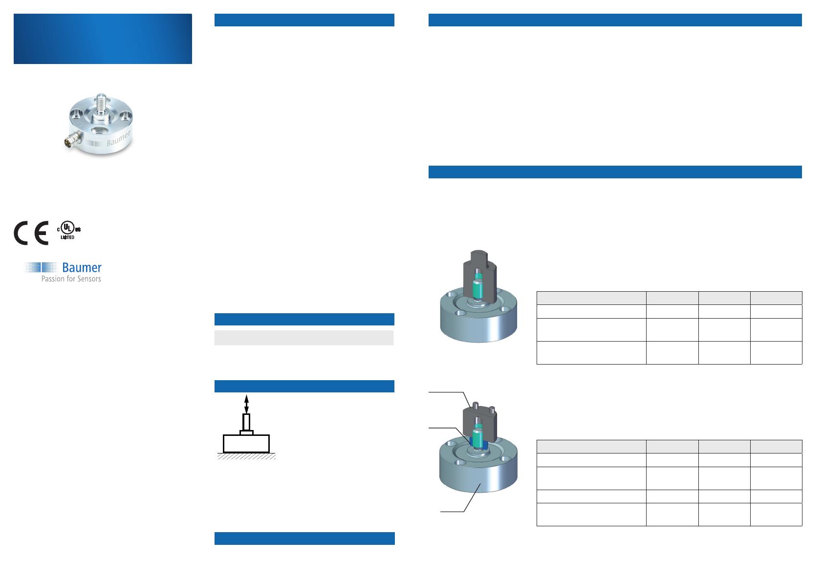
Baumer «Screw-on» force sensors are suitable for tensile and compressive force measurement in rough
industrial settings. Installation of the force sensors takes place in two steps. For the installation on the main
thread there are generally four different options available.
Installation options
Tool/counter piece is installed at the catch
Make sure that the thread length of the counter piece is deep enough. Use a
torque wrench for the installation on the main thread.
DLM20-SO DLM30-SO DLM40-SO
Thread on the counter piece M4 M6 M12
Min. thread depth in mm for
the main thread
9 13 25
Tightening torque in Nm on
the main thread
1 5 38
Tool/counter piece is bolted and xed with a lock nut
Make sure that the thread length of the counter piece is deep enough. Use a
torque wrench for the installation of the lock nut on the main thread.
DLM20-SO DLM30-SO DLM40-SO
Thread on the counter piece M4 M6 M12
Min. thread depth in mm for
the main thread
5 7 12
Nut height in mm 2.2 3.2 6
Tightening torque in Nm on
the main thread
1 5 38
tool
lock nut
sensor
Intended use
This product is a precision device and serves the
identication of items, objects or physical measure-
ments and the preparation or provision of measured
values as electric variables for the superordinate
system. Unless specically labeled, this product may
not be used in explosive environments. The product is
not intended for end users. Potentially additionally ap-
plicable EU directives must be veried by the device
manufacturer.
Start-up
Assembly, installation and calibration of this product
may only be performed by a specialist.
Installation
Only use intended fasteners and accessories for the
installation. Outputs not in use may not be wired.
Cable outputs with unused wires must be insulated.
Do not go below permissible cable bending radii. The
system must be switched off before electrically con
-
necting the product. If required, shielded cables must
be used to prevent electro-magnetic interference. If
the customer assembles plug connections to shielded
cables, then EMC-version plug connections should be
used. The cable shield must be connected to a large
area of the plug housing.
F
F
Tool/plate with through hole is xed full contact with a lock nut
The maximum thickness of the plate must not be exceeded. Use a torque
wrench for the installation of the lock nut on the main thread
Tool/plate with through hole is xed by a locknut on both sides
The maximum thickness of the plate must not be exceeded. Use a torque
wrench for the installation of the lock nut on the main thread.
DLM20-SO DLM30-SO DLM40-SO
Main thread M4 M6 M12
Diameter of the through hole
in mm
4.5 6.6 13.5
Height of the lock nut in mm 2.2 3.2 6
Tightening torque in Nm on
the main thread
1 5 38
Max. tool/plate thickness in
mm
5 8 17
DLM20-SO DLM30-SO DLM40-SO
Main thread M4 M6 M12
Diameter of the through hole
in mm
4.5 6.6 13.5
Height of the lock nut in mm 2.2 3.2 6
Tightening torque in Nm on
the main thread
1 5 38
Max. tool/plate thickness in
mm
2 3 7
The installation of the screw-on force sensors on the contact area is via four screws on a level and at
mechanically processed contact surface.
We recommend installation with a torque wrench and the following tightening torque for the applicable
sensor dimension
Installation from the top side
DLM20-SO DLM30-SO DLM40-SO
0.2 Nm 1.5 Nm 6 Nm
Tightening torques Screw-on force sensor
The following steps must be implemented during the installation of the force
sensor from above:
1. Drill four thread holes with the appropriate diameter at a 90-degree angle
into the desired installation surface. Observe the direction of the cable
outlet.
2. Select the appropriate screws for your sensor with the required length.
3. Clean the installation surface from soiling such as oil and grease.
Installation on the screw-on plate
DLM20-SO DLM30-SO DLM40-SO
Hole circle diameter in mm 21.0 30.0 47.0
Thread M2 M4 M6
Min. thread depth in mm 4 6 10
Recommended screw length in mm 10 16 25
Strength class 6.8 8.8 10.9
Installation from the bottom side
For the installation from the bottom side, the four threaded inserts included
in the packaging must be used. The following steps must be implemented for
the installation of the force sensor:
1. Drill four through holes with the appropriate diameter at a 90-degree angle
into the desired installation surface. Observe the direction of the cable
outlet.
2. Select the appropriate screws for your sensor with the required length.
3. Clean the installation surface from soiling such as oil and grease.
4. Place the thread inserts from above into the oval-shaped drill hole.
DLM20-SO DLM30-SO DLM40-SO
Hole circle diameter in mm 21.0 30.0 47.0
Diameter of the through drill holes
in mm
2.4 4.5 6.6
Strength class 6.8 8.8 10.9
F
F
F
F
F
ü
O O O O
+Vs
-Vs
Sig-
Sig+
2
3
4
1
3
4
1
2
Pin
1 +Vs
2 Sig +
3 –Vs
4 Sig –
Important
For reliable measurements, specific requirements for the installation surfaces and the force transmission
must be complied with. It is recommended to mechanically treat the contact surface.
The force must be
applied centrically.
Non-centrical
force application
leads to linearity
and sensitivity
deviations.
The force must
be applied axially.
Non-axial force
application leads
to linearity and
sensitivity devia-
tions.
The sensor con-
tact surface must
be smooth. A too
rough surface
leads to linearity
and sensitivity
deviations
The sensor
contact surface
must be sufcient-
ly rigid and may
not deform under
force. A too soft
contact surface
leads to sensitivity
deviations and in
extreme cases
to a failure of the
sensor.
Electrical connection
The DLMx0-SO force sensors are passive force sensors without electronic ampliers. The output signal is
mV/V and proportionate to the force. The measurement bridge of the force sensors is structured as follows.
As standard, Baumer force sensors are equipped with 4-pin plugs. The DLM20 version features an M5
plug, the DLM30 and DLM40 versions an M8 plug.
DLM20 DLM30 and DLM40
In addition, a constant voltage supply source is needed for reliable and repeatable measurements. Make
sure to operate the force sensors in the operating voltage range. For passive force sensors, the operating
voltage range is between 2 and 7 VDC (UL-Class 2).
Shielded cables are recommended for use with the force sensors.
Operation
Maintenance and repair
Disposal
Applicable documents
► Make sure that the sensor is assembled correctly
and only operated in the dened nominal force
range.
► To minimize the effect of settlement, fully load
the sensor 10 times, if possible.
Preventive maintenance
Regular maintenance is not required.
Repair
► Do not repair the sensor yourself.
► Return a damaged sensor to Baumer.
For contact addresses visit www.baumer.com.
► Do not dispose of in household
waste.
► Separate the materials and
dispose according to national
regulations.
For general notes see the insert sheet.
For technical data see the data sheet:
www.baumer.com
For accessories see www.baumer.com
1 / 1

Baumer DLM40-SO Installation and Operating Instructions

Type
Installation and Operating Instructions
This manual is also suitable for

Ask a question and I''ll find the answer in the document

Finding information in a document is now easier with AI

Ask the document