Page is loading ...

INSTALLATION, OPERATION & MAINTENANCE MANUAL
INTEGRATED PROGRAMMABLE CONTROLS
WWW.RENEWAIRE.COM
FOR EV450, ALL HE, LE
AND RD UNITS
Carel c.pCO Mini Carel c.pCOe Expansion Board

INTEGRATED PROGRAMMABLE CONTROLS
RENEWAIRE.COM INSTALLATION, OPERATION AND MAINTENANCE MANUAL 1.800.627.44992
IMPORTANT SAFETY INFORMATION
WARNING
Arc flash and electric shock hazard.
Microprocessor controllers as discussed in this manual are
typically installed in a control panel where high voltages are
present. Whenever accessing any controller, disconnect all
electric power supplies, verify with a voltmeter that electric
power is OFF and wear protective equipment per NFPA 70E
when working within the electric enclosure. Failure to comply
can cause serious injury or death.
The line side of the disconnect switch contains live high-voltage.
The only way to ensure that there is NO voltage inside the unit
is to install and open a remote disconnect switch and verify that
power is off with a voltmeter. Refer to unit electrical schematic.
Follow all local codes.
CAUTION
CAUTION
Risk of electric shock or equipment damage.
Whenever electrical wiring is connected, disconnected or
changed, the power supply to the ERV and its controls must
be disconnected. Lock and tag the disconnect switch or circuit
breaker to prevent accidental reconnection of electric power.
Risk of computer security breach.
This controller is capable of being connected to an ethernet.
Any device that is connected to an ethernet is susceptible to
unauthorized access and hostile activities. It is the owner’s
responsibility to determine acceptable risks and to safeguard
the security of the controller and all connected devices.
IMPORTANT
IMPORTANT
IMPORTANT
IMPORTANT
IMPORTANT
This equipment is only for use in protected environments. It is
not to be exposed to the weather or exposed to extremes in
temperature.
Only persons who have been properly trained and authorized are
to access the ERV control panel and the controller. Changes to
the controller programming are to be made only by trained and
authorized personnel. All changes to the controller programming
are to be documented in the Controller Maintenance Records
secion in this manual.
This control system is subject to periodic updates in firmware and the User Manual itself. Please consult the RenewAire.com website
to determine if you have the most recent manual and firmware.
Risk of degraded unit efficiency. Improper adjustment of unit
setpoints may result in the ERV operating inefficiently. Improper
selection of Input Offsets may cause incorrect or inefficient
operation of the ERV.
This equipment is to be installed by following Industry Best
Practices and all applicable codes. Any damage to components,
assemblies, subassemblies or the cabinet which is caused by
improper installation practices will void the warranty.

INTEGRATED PROGRAMMABLE CONTROLS
3 1.800.627.4499 INSTALLATION, OPERATION AND MAINTENANCE MANUAL RENEWAIRE.COM
OWNER INFORMATION
Record information as shown below. In the unlikely event that factory assistance is ever required, this
information will be needed.
Serial Number:
ERV Model Config Code:
Locate the RenewAire unit label, to be found inside the door or a removable panel on the appliance.
NOTE: This information is for purposes of identifying the specific air handling appliance. Unit-specific option
data can then be obtained, as needed, from the Model Number.
NOTE: this page is to
be completed by the
installing contractor. The
completed document is to be
turned over to the owner after
start-up.
UNIT RECORDS

INTEGRATED PROGRAMMABLE CONTROLS
RENEWAIRE.COM INSTALLATION, OPERATION AND MAINTENANCE MANUAL 1.800.627.44994
OWNER INFORMATION
TABLE OF CONTENTS
UNIT RECORDS 3
RENEWAIRE COMMERCIAL CONTROL CONFIGURATION CODE 7
1.0 OVERVIEW 8
1.1 DESCRIPTION 8
1.2 FIELD WIRING 8
2.0 COMPONENT DESCRIPTION 9
2.1 Controller 9
2.1.1 Controller Internal Memory 10
2.1.1 Controller External Memory 10
2.2 EXPANSION BOARD 11
2.3 REMOTE USER TERMINAL (RUT) 11
2.3.1 Connecting an RUT to the Controller 12
3.0 ASSOCIATED CONTROL SENSORS 13
3.1 WIRE GAUGE FOR FIELD-INSTALLED WIRING 13
3.2 CALIBRATION OF SENSORS 13
3.3 AIR QUALITY MONITOR 13
3.4 CO2 MONITOR 13
3.5 DUCT TEMPERATURE SENSOR 14
3.6 HUMIDITY TRANSDUCER 14
3.7 MOTION SENSORS 15
3.8 CURRENT SENSOR 15
4.0 USER INTERFACE 17
4.1 PASSCODE 17
4.2 CHANGING A PASSCODE 18
4.3 VIEWING CONTROLLER DATA VIA A COMPUTER 18
5.0 CONTROLLER MENUS 21
5.1 ACCESSING CONTROLLER MENUS 22
5.2 MENU MAP 23
5.3 MAIN MENU / UNIT STATUS SUBMENUS 25
5.3 MAIN MENU / UNIT STATUS SUBMENUS 26
5.5 MAIN MENU / SETTINGS SUBMENUS 31
5.6 MAIN MENU / ALARM SETTINGS SUBMENUS 34
5.7 MAIN MENU / UNIT ENABLE SUBMENUS 35
5.8 USER LOGIN 36
5.9 SERVICE MENU / BACK UP AND RESTORE SUBMENUS 36
5.11 SERVICE MENU / I/O CONFIGURATION SUBMENUS 37
5.10 SERVICE MENU / UNIT TYPE SUBMENUS 37
5.12 SERVICE MENU / I/O CALIBRATION SUBMENUS 38
5.13 SERVICE MENU / SENSOR OVERRIDES SUBMENUS 39
5.14 SERVICE MENU / TEST END DEVICES SUBMENUS 40
5.15 ALARMS 41
6.0 EMBEDDED MENUS 42
7.0 ALARMS 43
7.1 ACTIVE ALARMS 43
7.2 ALARM HISTORY 43
7.3 RESETTING ALARMS 43
8.0 UNIT STATUS 44
9.0 CONTROL VARIABLES 44
10.0 SETTINGS 44
11.0 ALARM SETTINGS 44
12.0 UNIT ENABLE 45
13.0 BACKUP AND RESTORE 45
13.1 BACKUP 45
13.2 RESTORE 45
13.3 WIPE / RETAIN 45
13.4 CHANGE PASSCODE 45
14.0 UNIT TYPE 45
15.0 I/O CONFIGURATION 46
16.0 I/O CALIBRATION 46
17.0 SENSOR OVERRIDES 46
18.0 TEST END DEVICES 46
19.0 BMS INTEGRATION 46
20.0 UNIT START-UP 47
20.1 FACTORY-INSTALLED PROGRAMMING 47
20.2 START-UP PROCEDURE 47
21.0 USER DEFAULT BACKUP RESTORE 48
21.1 BACKING UP SETTINGS 49
21.2 IMPORTING STORED SETTINGS FROM MEMORY 50
21.2.1 From USB 50
21.2.2 From NAND Internal Memory 50
21.3 RESETTING CONTROLLER TO FACTORY DEFAULTS 50
22.0 CONTROLS CONTRACTOR INFORMATION 51
22.1 BMS BACNET IP 51
22.2 BMS BACNET MSTP 51
22.3 BMS MODBUS IP 51
22.4 BMS MODBUS RTU 52
23.0 SEQUENCE OF OPERATION 53
24.0 TROUBLESHOOTING 62
25.0 INSTALLING FIRMWARE UPDATES 63
26.0 MAINTENANCE RECORDS 64
26.1 RECORD OF CONTROLLER SETTINGS 64
26.1.1 Setpoints 64
26.1.2 Offsets 64
26.1.3 IP Addresses 64
26.2 RECORD OF CHANGES TO CONTROLLER SETTINGS 65
26.2.1 Setpoints 65
26.2.2 Offsets 65
26.2.3 I/O Configuration Changes 65
26.3 RECORD OF WIPE RETAIN ACTIONS 66
26.4 RECORD OF CONTROLLER PROGRAM UPDATES 66
26.5 RECORD OF CONTROLLER SYSTEM DATA BACKUP 66
GLOSSARY 67

INTEGRATED PROGRAMMABLE CONTROLS
5 1.800.627.4499 INSTALLATION, OPERATION AND MAINTENANCE MANUAL RENEWAIRE.COM
TABLE OF ILLUSTRATIONS
COMMERCIAL CONTROLS Configuration Code 7
Carel c.pCO Mini controller 8
Carel Expansion Board 8
Remote User Terminal (RUT) 8
Controller Expansion Board 11
Remote User Terminal (RUT) 11
CO2 Sensor (duct mount, front view) 13
Indoor Air Quality Sensor duct mount) 13
CO2 Sensor (duct mount, side view) 13
Indoor Air Quality Sensor (wall mount) 13
Room CO2 Sensor (wall mount) 13
Duct Temperature Sensor 14
Humidity Transducer 14
Motion Sensor (ceiling mount) 15
Current Sensor 15
Motion Sensor (wall mount) 15
Pressure Differential Transmitter (typ) 16
Smoke Detector 16
Electronic Pressure Differential Transmitter 16
Sample Alarm Log 43
Sample Unit Parameter Log 48
TABLE OF WIRING SCHEMATICS
Sample Power Schematic 59
Sample Control Schematic 60
Sample Field Wiring Schematic 61

INTEGRATED PROGRAMMABLE CONTROLS
RENEWAIRE.COM INSTALLATION, OPERATION AND MAINTENANCE MANUAL 1.800.627.44996
IMPORTANT USER INFORMATION
SAVE THIS MANUAL
NOTICE
NOTICE
This manual contains space for maintaining written records of settings and changes. See Section
26, Maintenance Records. At the time the ERV is commissioned, a complete record (an operating
parameter file) should be made of all settings, to include setpoints and offsets. Whenever changes
are made to the controller data points, those changes should be recorded, along with the reason for
the change.
Information that is recorded is specific to just one ERV or controller. If additional controllers are
being documented, please make copies of these pages and identify each copy by its unit tag.
Whenever an operating parameter file is created in the controller internal memory, a backup file
should be created on an external memory device and stored in some convenient place.

INTEGRATED PROGRAMMABLE CONTROLS
7 1.800.627.4499 INSTALLATION, OPERATION AND MAINTENANCE MANUAL RENEWAIRE.COM
CONFIGURATION CODE
RENEWAIRE COMMERCIAL CONTROL CONFIGURATION CODE
COMMERCIAL CONTROLS Configuration Code
1 2 34 5 6 8 9 10 11 12 13 14 15 16 17 18 19 20 21 22 237 24 25
Model Number
Digit Number
Digits 1 thru 5:
“EV450”, “HE-1X”, “HE1.5”, “HE-2X”, “HE-3X”,
“HE-4X”, “HE-6X”, “HE-8X”.
J
Model Digit 21:
“T” = TRANSFORMER WITH ISOLATION RELAY
(STANDARD)
“1” = ENAHANCED CONTROLS
“2” = PREMIUM CONTROLS
“3” = ENHANCED CONTROLS W/BACNET LICENSE
“4” = PREMIUM CONTROLS W/BACNET LICENSE
Unit Control Enhancements
1 2 34 5 6 8 9 10 11 12 13 14 15 16 17 18 19 20 21 22 237 24 25
Model Number
Digit Number
Digits 1 thru 5:
“LE-6X”, “LE-8X”, LE10X”
J
Model Digit 21:
“T” = TRANSFORMER WITH ISOLATION RELAY
(STANDARD)
“1” = ENAHANCED CONTROLS
“2” = PREMIUM CONTROLS
“3” = ENHANCED CONTROLS W/BACNET LICENSE
“4” = PREMIUM CONTROLS W/BACNET LICENSE
Unit Control Enhancements
1 2 34 5 6 8 9 10 11 12 13 14 15 16 17 18 19 20 21 22 237 24 25
Model Number
Digit Number
J V
Digit 21:
“-” = TRANSFORMER WITH ISOLATION RELAY
(STANDARD)
“2” = PREMIUM CONTROLS
“4” = PREMIUM CONTROLS W/BACNET LICENSE
Unit Control Enhancements
Digits 1 thru 5:
“RD-2X”, “RD-4X”
Model
CONTROL CONFIGURATION CODE FOR EV/HE MODELS
CONTROL CONFIGURATION CODE FOR LE MODELS
CONTROL CONFIGURATION CODE FOR RD MODELS

INTEGRATED PROGRAMMABLE CONTROLS
RENEWAIRE.COM INSTALLATION, OPERATION AND MAINTENANCE MANUAL 1.800.627.44998
OVERVIEW
1.0 OVERVIEW
The RenewAire Commercial Controls package is available in either an Enhanced version or a Premium
version. The enhanced control package uses a custom-programmed Carel c.pCO Mini controller to
manage the following:
Either control package may be installed as a stand-alone controller, capable of being monitored and
adjusted as needed directly on the controller, or it can be installed as part of a Building Management
System (BMS). It is compatible with several BMS protocols. See Section 19 BMS Integration in this manual
for more information.
NOTE: This unit is a micro-
processor controller. It is
commonly referred to as a
“controller”.
Carel c.pCO Mini controller
Carel Expansion Board
Remote User Terminal (RUT)
• Automatically enable and disable the unit
• Enable the exhaust fan only
• Filter alarm for both sets of filters
• Bypass controls
• Control isolation dampers
• Supply fan only modulation
• Exhaust fan only modulation
• Defrost controls (Canada only)
• Smoke detection
• Provide Supply and Exhaust air temperatures
• Provide outside and return air temperature and humidity
• Fan status
• Enable the supply fan only
• Enable the exhaust fan only
• Monitor and log alarm conditions
Note: Many of these control features
require the use of optional sensors.
The unit configuration will determine
the availability of some functions.
The Premium control package consists of a c.pCO Mini controller and a c.pCOe expansion board. This
package will perform all of the above and also perform the following:
• Monitor/report outside airflow rate
• Monitor/report exhaust airflow rate
• Provide space pressure control
• Provide duct pressure control
• Unit supply air temperature
• Enable heating
• Provide modulation of heating - either staged or modulated
• Provide modulation of cooling - either staged or modulated
The controller and the optional expansion board are factory-wired to a low voltage terminal board and a
24VAC power source at the factory. Termination of field-installed sensors is made to the terminal board
during the installation process. Connection to a BMS is accomplished by connecting the BMS cable to Serial
Port J3 or to the RJ25 jack.
1.2 FIELD WIRING
1.1 DESCRIPTION

INTEGRATED PROGRAMMABLE CONTROLS
9 1.800.627.4499 INSTALLATION, OPERATION AND MAINTENANCE MANUAL RENEWAIRE.COM
OVERVIEW
2.0 COMPONENT DESCRIPTION
The c.pCO (pronounced see pee-ko) Mini has a number of digital and analog inputs and outputs that
enable it to monitor multiple sensors and then provide control signals to different hardware in the HVAC
system. It will assess the inputs and monitors to detect error conditions and both report them as alarms
and record the occasions in the form of a log. It has a digital readout screen and a set of hard buttons that
are used to navigate through menus. The device can also be accessed from a remote computer through
an ethernet connection. The unit Sequence of Operation (SOO) is programmed into the controller and it
then provides direct control of the unit, operating the unit within the parameters installed by the factory
and modified by the user.
The controller has an integral USB port that can be used as a memory output to a USB thumb drive or it
can be used to input updated control programming. There is a substantial internal memory to provide for
storage of many different operating profiles, which can be selected as desired.
The controller also has an integral alarm to provide an audible warning of an Error condition.
C.pCO n° (03)
75.5°F
Time 12:33
date: 07.06.2017
14
5
3 4 7 11
12
6
9
10
12
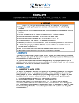
2.1 Controller
Power connector
Universal inputs / outputs
+Vterm: terminal power supply
Terminal connector
Relay digital outputs
+5VREF: power supply for ratiometric probes
FieldBus connector
Analog outputs
Digital inputs
CANbus connector
Ethernet port
Micro USB-B port
1
2
3
4
5
6
7
9
10
11
12
14

INTEGRATED PROGRAMMABLE CONTROLS
RENEWAIRE.COM INSTALLATION, OPERATION AND MAINTENANCE MANUAL 1.800.627.449910
OVERVIEW
2.1.1 Controller External Memory
2.1.1 Controller Internal Memory
The controller has a built-in USB port where an external memory device such as a USB thumb drive can be
plugged in. The external memory device may be used for backing up all settings and reported conditions
such as Alarm History and presets. Backing-up is user-commanded and is done through the Service Menu
/ Back Up and Restore.
Note that the USB port is a Micro USB Type “B”. Thumb drives with a Micro USB Type B are difficult to find in
some areas and it may be necessary to purchase an adapter to go from a more common Type A connector
to the newer Micro Type B.
Micro USB Type “B” Port
Note: RenewAire highly recommends that a USB thumb drive be installed in the
USB port and a system backup (external) be made immediately after start-up or
commissioning.
The controller has a total of about 92 MB of internal memory and uses about 15 MB for its internal
programming. Approximately 75 MB remains for use by the user for backup files. An individual backup file
normally requires about 200 KB.

INTEGRATED PROGRAMMABLE CONTROLS
11 1.800.627.4499 INSTALLATION, OPERATION AND MAINTENANCE MANUAL RENEWAIRE.COM
OVERVIEW
2.2 EXPANSION BOARD
The c.pCOe expansion board has multiple digital and analog inputs and outputs, serving as an extension
of the controller. The expansion board is included as part of the Premium controls package and permits
modulation for either heating or cooling, enable heating, monitor airflow rates and temperatures and
pressures.
2.3 REMOTE USER TERMINAL (RUT)
The RUT is an optionally available device that mirrors the c.pCO controller. All the information that is
available on the controller can be viewed on the RUT and user inputs can also be performed on the RUT.
The RUT is connected to the controller by means of a straight-through 6-wire cable. It is possible to
connect more than one RUT but instructions from Carel are required. RUTs are generally connected to the
controller by means of a 10’ cable and then used as hand-held devices. They can alternately be installed
on a wall in some convenient loaction. The maximum distance between the RUT and the controller is
normally 164 feet, but that can also be increased by following special instructions from Carel. There is an
audible alarm built in that sounds whenever an Error condition exists.
The push buttons on the face of the RUT have the same functions as the push buttons on the controller.
1
2
3
4
5
6
7
8
9
10
11
12
13
14
15 with oset
no oset
19.2 K
9.6 K
38.4 K
57.6 K
CAREL
Modbus
ON
OFF
Address Ext. ProtBaud
Basic version
6
8
8
5
1
11
2
Address Ext Baud Prot
Controller Expansion Board
Remote User Terminal (RUT)
1
2
5
6
8
11
Power supply
Universal inputs / outputs
Relay digital outputs
Power supply for ratiometric probes
BMS port
Dip switches

INTEGRATED PROGRAMMABLE CONTROLS
RENEWAIRE.COM INSTALLATION, OPERATION AND MAINTENANCE MANUAL 1.800.627.449912
OVERVIEW
Back of RUT
The Remote User Terminal (optional accessory, field-installed) plugs into the controller by means of a six-
wire cable with RJ12 jacks on each end. The six-wire cable is inserteted in the RJ12 jack on the back of
the RUT and othe other end of the cable is inserted into the RJ12 adapter, found in the low voltage electrical
compartment. The controller uses a pre-configured cable that plugs into the J3 jack on the controller and
the other end is plugged into the RJ12 adapter. The cable from the controller to the low voltage electrical
box is factory-installed.
Note: The RUT is nor-
mally used as a hand-
held device but it may
also be mounted on a
wall or other surface
by means of the screw
head recesses on the
back of the device.
Note: Common
telephone wiring is 4
conductor and uses
RJ11 terminals. It is
easily confused with
the six-wire cable with
RJ12 terminals needed
for this accessory .
When connecting one RUT to the controller, a 6-wire straight-through cable is used for both data
transmission and power to the RUT. If there is more than one RUT, if the distance is greater than 164 feet
or if some other configuration is needed, see the Carel c.pCO User Manual.
2.3.1 Connecting an RUT to the Controller
Low Voltage
Electrical
Compartment
Note that if the controller was ordered for use with a BMS and an RUT is also desired, contact the factory
for further information.

INTEGRATED PROGRAMMABLE CONTROLS
13 1.800.627.4499 INSTALLATION, OPERATION AND MAINTENANCE MANUAL RENEWAIRE.COM
OVERVIEW
(optional accessory, field-installed)
The Air Quality Monitor detects total VOCs (TVOC) in the Supply Airstream. It uses a MEMs metal oxide
semiconductor sensor to capture VOC emmissions that are invisible to CO2 sensors. As part of a Premium
Controls package, it is used to provide speed control to fans that are controlled by VFDs or EC fan motors.
It is installed in the Supply Air duct. When used as part of a Standard or Enhanced Controls package, it can
be used as an ON / OFF control.
(optional accessory, field-installed)
Used as part of a demand control ventilation system. Used in the Premium Controls package to provide
speed control of fans that are controlled by VFDs or by EC motors. When used as part of a Standard or
Enhanced Controls package, it can be used as an ON / OFF control.
Indoor Air Quality Sensor duct mount)
CO2 Sensor (duct mount, front view) CO2 Sensor (duct mount, side view) Room CO2 Sensor (wall mount)
Indoor Air Quality Sensor (wall mount)
Field-installed control sensors and monitors are to be installed and wired in accordance with instructions
shipped in the documentation package. Wire gauge must be in accordance with the following:
Wire Gauge #22 #20 #18 #16 #14 #12
Circuit Length 100’ 150’ 250’ 400’ 700’ 1000’
Sensors will normally last the life of the unit without significant attention. As sensors age, they may
become slightly out of tolerance and require an offset adjustment by using the Service Menu / Input
Calibration screens.
3.1 WIRE GAUGE FOR FIELD-INSTALLED WIRING
3.2 CALIBRATION OF SENSORS
3.3 AIR QUALITY MONITOR
3.4 CO2 MONITOR
3.0 ASSOCIATED CONTROL SENSORS

INTEGRATED PROGRAMMABLE CONTROLS
RENEWAIRE.COM INSTALLATION, OPERATION AND MAINTENANCE MANUAL 1.800.627.449914
OVERVIEW
(replacement part only, factory-installed)
Duct temperature sensors are factory-installed in EA and FA compartments. They are used in Standard,
Enhanced and Premium Controls packages.
(replacement part only, factory-installed)
Humidity transducers are used in both the Enhanced and the Premium Control packages. They are mounted
in the OA and RA compartments and provide an output from 0-10 VDC. Used in Enhanced and Premium
Controls packages.
Duct Temperature Sensor
Temperature & Humidity Sensor
3.5 DUCT TEMPERATURE SENSOR
3.6 HUMIDITY TRANSDUCER

INTEGRATED PROGRAMMABLE CONTROLS
15 1.800.627.4499 INSTALLATION, OPERATION AND MAINTENANCE MANUAL RENEWAIRE.COM
OVERVIEW
Current Switch
(optional accessory, field-installed)
Used for occupancy-based ventilation, available with the Premium package. Hardwired to the low voltage
terminal strip. Used in Premium Controls packages.
(replacement part only, factory-installed)
Installed on high voltage supply wires to sense current going to a motor. They are used to prove the ON /
OFF state of fan motors. Used in Enhanced and Premium Control packages.
Motion Sensor (ceiling mount) Motion Sensor (wall mount)
3.8 CURRENT SWITCH
3.7 MOTION SENSORS
Note that current sensors are calibrated for reduced fan speed at time of shipment from the
factory. Immediately after entering new operating parameters for the fans (done during the
start-up process), current sensors are to be recalibrated for full current draw.
On the top of the sensor, there are an adjusting screw and two LED lights, one red and one blue. The
adjusting screw will turn 15 turns. To set the sensor for any fixed-speed fan,
• Verify that the blue LED is on.
• Slowly adjust the potentiometer screw clockwise until the RED LED just turns on. This sets the trip
point at the normal operating load current
• If the RED LED is on after intial power-up, slowly adjust the potentiometer counter-clockwise until the
BLUE LED turns on and then slowly adjust the potentiometer clockwise until the RED LED just turns on.
Note that if the fan is variable speed, the fan should be running at its minimum speed.

INTEGRATED PROGRAMMABLE CONTROLS
RENEWAIRE.COM INSTALLATION, OPERATION AND MAINTENANCE MANUAL 1.800.627.449916
OVERVIEW
(optional accessory, field and factory-installed)
Detects differences in static pressures. Typically surface-mounted, often on a duct, sometimes on a wall.
Used in Premium controls packages as an optional accessory. Transmitters without a display are also used
in Enhanced and Premium Controls packages as filter monitors and for airflow measurement.
(optional accessory, field-installed)
Used in both the Enhanced and Premium packages. Normally field-installed on the discharge duct, near
the furnace.
Pressure Differential Transmitter (typ)
(+/- 2% accuracy)
Electronic Pressure Differential Transmitter
(+/- 0.5% accuracy)
Smoke Detector
3.9 PRESSURE DIFFERENTIAL TRANSMITTERS
3.10 SMOKE DETECTOR

INTEGRATED PROGRAMMABLE CONTROLS
17 1.800.627.4499 INSTALLATION, OPERATION AND MAINTENANCE MANUAL RENEWAIRE.COM
OVERVIEW
4.0 USER INTERFACE
The user will interface with the controller by any of several methods:
1. The push buttons and digital readout on the face of the controller
2. The push buttons and digital readout on an optional RUT
3. Controls provided by the user that are part of a Building Management System (BMS)
4. Owner-supplied remote computer, connected via ethernet
Pressing the PRG (program) button accesses the Service Menu or Login screen from any location in the user interface screens.
The options that are available dynamically change depending on the configuration of the unit and the options installed on the
unit.
The ESC button is used to go one level back from the screen the user is currently on. If the user is finished setting variables in
a sub-menu, the ESC button takes them back to the previous menu. If the user is editing a variable and decides to not make a
change, the ESC button takes them back to the top of that screen. Pressing the ESC button from the Main Menu takes the user
back to the Main Status screen.
In a menu, the UP and DOWN hard buttons scroll through the options that a user can access. When viewing the Unit Status loop,
the UP or DOWN hard buttons move the user from one screen to the next. While editing a variable, the UP or DOWN hard buttons
buttons allow the user to set the desired value of the variable. When viewing a view only variable, the UP or DOWN hard buttons
scroll through the values available to the user.
When a menu or menu item has been highlighted, press the ENTER hard button to enter the highlighted selection. When a
writable entry has been changed, press the hard button to enter the new value and then press it again to confirm the change.
Pressing the ALARM button displays any alarms that are currently active. There may be multiple screens of alarms. Pressing and
holding the Alarm button for three seconds resets the alarms.
NOTE: When an alarm is first detected, the Alarm button will be flashing and an audible alarm will
sound. After the alarm has been viewed, the light will remain on and the audible alarm will stop.
4.1 PASSCODE
Three levels of access are built into the controller. The first level is available to anyone and it includes the Home screen, the System Status
screens, the Main Menu and the Alarm screen. This level of access allows a user to view many of the screens and make adjustments to setpoints
and offsets. The second level of access is Service Access and this requires the user to enter a passcode. There are two different Passcodes. The
first passcode is “User” and is set at 0000. It permits access to the Service Menu as read-only. The second Passcode is “Service” and it allows
read/write access to the Service Menu. The second Service passcode is factory-set at 1000. When the PRG button is pressed, a Login screen
appears that requires a Passcode before the Service menu can be accessed. Access each of the digits in the passcode by pressing the ENTER
button and then use the UP and DOWN arrow buttons to change the value of each digit.
A Factory passcode is also programmed into the controller to permit a factory representative to override a lost or corrupted Service passcode.
The Factory passcode is only available from the factory and is not given out unless there are extenuating circumstances.

INTEGRATED PROGRAMMABLE CONTROLS
RENEWAIRE.COM INSTALLATION, OPERATION AND MAINTENANCE MANUAL 1.800.627.449918
OVERVIEW
4.3 VIEWING CONTROLLER DATA VIA A COMPUTER
Any device that has an IP (Internet Protocol) address can be accessed directly from a computer connected
to the device. The controller has an IP address and when it is accessed, an interactive screen appears that
allows the user to move through all the controller menus. The IP address of the controller is factory-set at
10.10.1.2. The subnet address (needed for setting up a LAN) is set at 255.255.255.0.
To access controller data from a computer, set up a Local Area Network (LAN) on the computer, using the
IP and subnet addresses shown above. Open an internet browser and enter the IP address (a string of
numbers) into the address line. Click ENTER.
4.2 CHANGING A PASSCODE
The User and Service passcodes can be changed by the user from within Service Menu / Backup and
Restore / Unit Configuration. Scroll down to the Change Passscode screen by using the DOWN arrow
button.
1. Install a connector cable from the RJ45 ethernet jack on the controller to an ethernet jack on the
computer.
2. On the controller, press and hold both the ALARM and ENTER keys for about three seconds in order to
access the embedded INFORMATION screen.
3. Select SETTINGS then click ENTER
4. Navigate to TCP/IP Settings, click ENTER
5. Verify that the IP address is set for 10.10.1.2
6. Verify that the Mask is set for 255.255.255.0

INTEGRATED PROGRAMMABLE CONTROLS
19 1.800.627.4499 INSTALLATION, OPERATION AND MAINTENANCE MANUAL RENEWAIRE.COM
OVERVIEW
Configure the computer to communicate with the controller.
7. Turn OFF wireless (wi-fi) connections.
8. In Windows 10, go to Network and Sharing Center.
Click on Connections: Ethernet
Click on PROPERTIES
A scroll-down menu appears, select and double-click on Internet Protocol Version 4 (TCP/IPv4)

INTEGRATED PROGRAMMABLE CONTROLS
RENEWAIRE.COM INSTALLATION, OPERATION AND MAINTENANCE MANUAL 1.800.627.449920
OVERVIEW
Complete the computer’s IP address: 10.10.10.1
Complete the computer’s Subnet Mask: 255.255.255.0
Click OK
Click OK
Click CLOSE
Go to the computer’s web browser and type in the address bar: 10.10.1.2 Press ENTER.
This will activate the connection between the controller and the computer and produce the following screen:
A menu is shown directly above the image of the RUT. Click on menu item “RUT”. The resulting interactive
image of an RUT will show the same screen images as the images shown on the controller, in all respects.
Menu Bar
/