Page is loading ...

This unit should be started up for a brief period immediately after high and low-voltage wiring are complete. The purpose of the
initial start-up is only to verify correct fan rotation direction and that the dampers are opening and closing properly. After the unit
has been run for a brief period, it is to be shut back down until the entire installation is complete. The unit is not to be used for
building ventilation before the building has been completed.
PRIOR TO UNIT START-UP:
RISK OF ELECTRIC SHOCK OR EQUIPMENT DAMAGE
Whenever electrical wiring is connected, disconnected or
changed, the power supply to the unit and its controls must
be disconnected. Lock and tag the disconnect switch or
circuit breaker to prevent accidental reconnection of
electric power.
CAUTIONCAUTION
RISK OF CONTACT WITH HIGH-SPEED MOVING PARTS.
Disconnect all local and remote power supplies, verify with
a voltmeter that electric power is off and all fan blades have
stopped rotating before working on the unit.
Do not operate this unit with any cabinet panels removed.
CAUTION
To insure the quality of the installation and the proper operation of this unit, the following Start-Up routines should be completed. Please follow
the procedures and recommendations identified in this report and record start-up information in the specified areas. If a problem with the unit
becomes apparent, correct the problem by referring to the installation manual or contact the Factory Representative for further assistance.
Please verify the accuracy of all model and serial number information before contacting the manufacturer.
Commercial ERV Units with
Commercial Controls
Start-up Guide
JOB NAME: TAG: DATE:
MODEL NO: SERIAL NO:
CONTRACTOR: TESTED BY:
The unit must be in its final location.
Verify all prefilters are in place and on the correct airstreams (i.e. inlet face of core exhaust and the inlet face of the core
supply) if previously removed.
High-voltage supply wiring must be complete.
All low-voltage wiring, including field-installed sensors, must be completed.
All debris or construction materials must be removed from the unit.
All doors and access panels must be in place.
Initial start-up should not be performed if the air is laden with construction dust. Filters will quickly become dirty and require
changing for other subsequent testing.
If this unit was purchased with a Remote User Terminal (RUT) for the controller, connect the RUT and perform start-up steps
with the RUT. If there is no RUT, perform the start-up steps by using the buttons on the Integrated Programmable Controller or
the internal web pages.
Make sure all power to the unit is “off” and all disconnects are in the “off” position before making final power connections
FOR INDOOR UNITS: Confirm that the supply and exhaust vent connections have been properly connected and the penetration
points have been separated by a minimum of 10', are free of obstructions, and are screened and properly terminated as per
directions. Inspect the OA and EA vent pipes to confirm that they are pitched ¼" per foot away from the unit and insulated
with vapor barrier insulation.
FOR ROOF TOP UNITS: Inspect and confirm that all ductwork has been connected and sealed as per installation instructions.
Confirm circuit breaker amperage does not exceed the MOP on the nameplate and verify the unit is wired with the correct
line voltage.
Set sheaves using unit ratings table and job design requirements. Check the belts for proper tension and pulley alignment if an
adjustment has been made. (Belt drive units only).
Spin each blower wheel to assure they are not rubbing and are in alignment in the blower housing.
Check all set screws and fasteners on blowers, bearings, sheaves, and drives (if adjustments have been made) to
assure tightness.
Installation of unit and electrical wiring must be done by a qualified professional(s) in accordance with all applicable codes,
standards and licensing requirements. Before servicing or cleaning the unit, switch power “off” at the disconnect switch or
building service panel and lock-out/tag-out to prevent power from being accidentally turned on. This unit must be grounded as
per instructions.
WARNING

ERV Start-up Guide
1.800.627.44992
WARNING
ARC FLASH AND ELECTRIC SHOCK HAZARD
All RenewAire models operate on high voltages that can cause severe electric shock. Some models use high voltages that are
capable of causing dangerous arc flash. Whenever accessing any part or component of the unit, disconnect all electric power
supplies, verify with a voltmeter that electric power is OFF and wear protective equipment per NFPA 70E when working within
the electric enclosure. Failure to comply can cause serious injury or death.
The unit disconnect switch contain live high-voltage.
The only way to ensure that there is NO voltage inside the unit is to install and open a remote disconnect switch and verify
that power is off with a voltmeter. Refer to unit electrical schematic.
Follow all local codes.
u Each screen has a bar at the top to show within which set of menus it resides.
u Access the Main Menus by pressing the Escape button.
u Access the Service Menus by pressing the Program Button and entering the password 1000.
CONTROL MENU STRUCTURE
NOTE: For more in-
formation regarding
setpoints and unit
configurations, see
the Commercial Controls
User Manual furnished with
the unit.
u Pressing Up and Down when the cursor is in the upper left-hand corner will move you from screen to screen.
u Pressing Enter on a screen will move from field to field and Up and Down on another field will change the value.
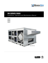
OPTIONAL REMOTE USER TERMINAL (RUT)
ESCAPE BUTTON
ENTER BUTTON
UP BUTTON
DOWN BUTTON
PROGRAM BUTTON
ALARM BUTTON
INTEGRATED PROGRAMMABLE CONTROLLER
ENTER BUTTON
ALARM BUTTON
PROGRAM BUTTON
UP BUTTON
DOWN BUTTON
ESCAPE BUTTON

ERV
Start-up Guide
31.800.627.4499
The controller needs the correct time and date for alarm stamps, etc.
The unit of measure setting will determine the values that show on the display.
SET THE TIME AND UNIT OF MEASURE
Using these two screens, confirm that the unit has the correct configuration. Heating and cooling are available with premium
controls only.
CONFIRM THE CONFIGURATION
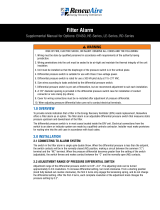
If using premium controls and require the ability to control airflow based on CO2, VOC, Duct Static, or room static, the sensor
must be enabled here and installed on the unit. Any scaling can be adjusted in the screens following, if needed.
If using premium controls for heating and/or cooling, the supply air temperature sensor must be enabled and installed.
ADD ANY REQUIRED SENSORS
CA TEMPERATURE SENSOR
P/N 131318
1
2
3
4
5
6
7
8
9
10
11
12
13
14
15 with oset
no oset
19.2 K
9.6 K
38.4 K
57.6 K
CAREL
Modbus
ON
OFF
Address Ext. ProtBaud
Address Ext Baud Prot
EXPANSION MODULE
X3-27 X3-26
X3 TERMINALS
21
22
23
24
25
26
27
28
SENSOR 24VAC
CO2 LEVEL
SPACE PRESSURE
DUCT PRESSURE
CA TEMPERATURE
SENSOR COMMON
30
29
VOC LEVEL
FACTORY WIRING FIELD WIRING

ERV Start-up Guide
1.800.627.44994
1
2
3
4
5
6
7
8
9
10
11
12
13
14
15 with oset
no oset
19.2 K
9.6 K
38.4 K
57.6 K
CAREL
Modbus
ON
OFF
Address Ext. ProtBaud
Address Ext Baud Prot
EXPANSION MODULE
X3-25 X3-27
DUCT PRESSURE SENSOR
P/N 131315
X3-21
1
2
3
4
5
6
7
8
9
10
11
12
13
14
15 with oset
no oset
19.2 K
9.6 K
38.4 K
57.6 K
CAREL
Modbus
ON
OFF
Address Ext. ProtBaud
Address Ext Baud Prot
EXPANSION MODULE
X3-27X3-22
X3-21
CO2-W OR CO2-D SENSOR
P/N 131304 OR 131305
1
2
3
4
5
6
7
8
9
10
11
12
13
14
15 with oset
no oset
19.2 K
9.6 K
38.4 K
57.6 K
CAREL
Modbus
ON
OFF
Address Ext. ProtBaud
Address Ext Baud Prot
EXPANSION MODULE
X3-27X3-23
X3-21
IAQ-W OR IAQ-D SENSOR
P/N 131308 OR 131307
1
2
3
4
5
6
7
8
9
10
11
12
13
14
15 with oset
no oset
19.2 K
9.6 K
38.4 K
57.6 K
CAREL
Modbus
ON
OFF
Address Ext. ProtBaud
Address Ext Baud Prot
EXPANSION MODULE
X3-27 X3-25
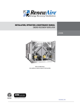
DUCT PRESSURE SENSOR
P/N 131309
X3-21

ERV
Start-up Guide
51.800.627.4499
1
2
3
4
5
6
7
8
9
10
11
12
13
14
15 with oset
no oset
19.2 K
9.6 K
38.4 K
57.6 K
CAREL
Modbus
ON
OFF
Address Ext. ProtBaud
Address Ext Baud Prot
EXPANSION MODULE
X3-24 X3-27
SPACE PRESSURE SENSOR
P/N 131314
X3-21

ERV Start-up Guide
1.800.627.44996
If using enhanced controls and variable
speed fans, you will be allowed to set the
variable speed fans to a specific fan speed
as a percentage.
If using premium controls with variable
speed fans you will have these additional
options. Choose your type and set the
corresponding settings for that type.
CONFIGURE AIRFLOW FOR SUPPLY AND RETURN FANS
NOTE: FOR AIRFLOW CONTROL WITH VFDS YOU MAY NEED TO SET THE KP VALUES AS LOW AS 0.1 TO PREVENT HUNTING.

ERV
Start-up Guide
71.800.627.4499
Repeat for exhaust fan.
UNIT START-UP:
Start the unit through the keypad. The digital input ID1 (terminals 17–18) has to be closed. See the images on the below.
The unit is now powered up and the dampers should begin moving. Once the dampers are in their programmed positions, the
fans will begin to run.
Verify that fans are turning the correct direction and that dampers are functioning. If fan rotation is reversed, change any two
of the three-phase high-voltage supply wires to the motor.
MAIN MENU SCREEN HIGHLIGHT AND PRESS ENTER ON UNIT ENABLE CLICK UP OR DOWN ARROW BUTTON TO CHANGE
STATUS TO ON.
CLICK THE ESCAPE BUTTON TO RETURN TO THE
MAIN MENU.

ERV Start-up Guide
1.800.627.44998
Member of the S&P Group
Family of Brands
2022 © RenewAire LLC
138352_003_JUL22
ENGINEERED DESIGN CONDITIONS ACTUAL PERFORMANCE CONDITIONS
EXHAUST
(RA) CFM E . S .P. BLOWER
R.P.M.
EXHAUST
(RA) CFM E . S .P. BLOWER
R.P.M.
SUPPLY
(FA) CFM E . S .P. BLOWER
R.P.M.
SUPPLY
(FA) CFM E . S .P. BLOWER
R.P.M.
MCA
(MIN CIR. AMPS)
MFS
(MAX FUSE SIZE) MOTOR AMPS (OA) MOTOR AMPS (EA)
UNIT
VOLTAGE:
LINE VOLTAGE
L1-L2 L2-L3 L3-L1
Observe this status screen for status of fans and unit. All four answers should be “YES” and the Unit should show UNIT ON. If the
Fan On is NO when the fans are running the current switch for that fan needs to be adjusted.
Shut down the unit by switching UNIT ON/OFF back to OFF and turning the disconnect switch to OFF.
SECURE ALL PANELS AND DOORS TO PREVENT ACCIDENTAL ACCESS TO LIVE HIGH-VOLTAGE OR TO THE FANS.
u Confirm that the correct heating type is set. Make sure the connections are physically in place.
u Choose to control to the heating setpoint or to a reset schedule with outdoor air.
u Choose between control off supply or return air.
u Be sure to make sure the outdoor air lockout temperature is below the current outdoor temperature.
u Depending upon the heating type, set the appropriate setting. Refer to the appropriate manual to proceed for heating
checkout.
SET THE HEATING SETTINGS
/