Page is loading ...

Printed in Japan 2016/7 EG-2300E 274-0575-11
Installation Manual
EG-2300E
SurroundEye Control Box
●
Thank you very much for your purchase of this Clarion product.
●
To get the best performance from and to use this device effectively, first read this Installa-
tion Manual thoroughly and then install the device correctly and safely.
Clarion Co., Ltd.
All Rights Reserved. Copyright © 2014 : Clarion Co., Ltd.
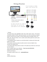
THE SURROUNDEYE CONTROL BOX
This camera ECU box can supply power to up to 4 cameras, process the images output by the
cameras and then output the images to the LCD monitor.
■
Compatible with DC 12V/24V vehicles
■
Starts up when ACC (or IG) is ON
■
Can be connected to Clarion cameras (NTSC std.)
■
Outputs images (NTSC std.) to monitor via RCA connectors
■
Setup (calibration) of the camera ECU is achieved using special software on a PC connected
via an interface box
■
An optional switch can be connected for switching the screen
SAFETY PRECAUTIONS
Always follow the safety precautions below when installing the device.
WARNING
●
Before making connections, disconnect the negative battery terminal.
Failure to do so may result in electric shock or injury due to short-circuit.
●
Discontinue use in the event of malfunction or abnormality.
●
Route the cables and bundle them with tape or the like so that they do not interfere with
driving operation.
If a cable coils around the steering column, gear lever, brake pedals, etc., it may lead to an accident.
●
Do not attempt to disassemble or modify the unit.
Never attempt to disassemble or modify the unit. Doing so may result in accident, fire, electric shock or
other malfunction.
●
Never use the vehicle's safety-related parts* for mounting or grounding the device.
* Nuts and bolts in the steering system, seat rails, brake system, tanks, etc.
Doing so may result in loss of control, fire or traffic accident.
●
Do not install this device in the following kind of places.
• Places that would obstruct the view to the front
• Places that would obstruct driving operations, such as the steering wheel, shift lever or brake pedal
• Places that present a hazard to passengers
Doing so may result in accident or injury.
●
Never mount or make connections in a place that would obstruct operation of the air
bags.
Mounting or making connections in a place that obstructs air bag operation will cause a problem if the
air bag system cannot operate properly during a car accident.
●
If installation of the device requires making a hole in the chassis, check the position of the
pipes, tanks, electrical wires, etc. and be sure to avoid interference or contact. Also, take
steps to prevent rust and water penetration.
Damaged pipes or other parts may lead to fire or electrical shock.
●
Never cut the insulation on the power cord to power another device.
Doing so will overload the cord and may cause a fire or electrical shock.
●
After completing installation and wiring work, check and make sure the vehicle's electri-
cal equipment* is working properly.
* Brakes, lights, horn, hazard lamps, blinkers, etc.
Malfunctioning equipment may lead to fire, electric shock or traffic accident.
●
Never drive looking solely at the monitor. This is an auxiliary device to supplement the
driver’s field of vision ; it does not show all hazards or obstacles. Actual distances and
perceptions may differ, so be sure to visually check safety while driving. Failure to do so
creates the risk of hitting a person or object in the camera’s blind spot, causing a serious
accident.
CAUTION
●
Entrust the installation and any modifications to the installation to an expert.
Failure to do so may result in an accident or fire. Contact the dealer where the device was purchased.
●
When installing the device on a vehicle with air bags, check the warnings on such work
provided by the maker of the vehicle before performing the work.
Failure to do so may result in malfunction of the air bags.
●
Follow the instructions in the manual when mounting and connecting the device.
Incorrect installation and/or connection may result in fire or accident.
●
Be sure to use the accessories and specified parts.
Using components other than those specified may lead to damage of the parts inside the device or the
inability to secure them firmly, resulting in them becoming detached and leading to an accident or mal-
function.
●
After wiring the various cords, secure them with clamps and/or insulating tape.
If the cables come into contact with the chassis, they will fray and short-circuit, leading to an accident or
fire.
●
Route the cables so that they do not get caught in the chassis, screws, seat rails or other
moving parts.
Damaged or short-circuited cables may result in an accident, electric shock or fire.
●
Never mount in a location subject to a lot of vibration or where it cannot be securely fas-
tened.
If the unit comes loose, it may result in an accident or injury.
●
Do not install in a location subject to direct sunlight or hot air from the heater.
The temperature inside the unit may get too high, resulting in fire or damage.
PRECAUTION
This equipment has been tested and found to comply with the limits for a Class B digital device,
pursuant to Part 15 of the FCC Rules.
These limits are designed to provide reasonable protection against harmful interference in a resi-
dential installation.
This equipment generates, uses, and can radiate radio frequency energy and, if not installed and
used in accordance with the instructions, may cause harmful interference to radio communica-
tions. However, there is no guarantee that interference will not occur in a particular installation.
If this equipment does cause harmful interference to radio or television reception, which can be
determined by turning the equipment off and on, the user is encouraged to consult the dealer or
an experienced radio/ TV technician for help.
■
INFORMATION FOR USERS:
CHANGES OR MODIFICATIONS TO THIS PRODUCT NOT APPROVED BY THE MANUFACTUR-
ER WILL VOID THE WARRANTY AND WILL VIOLATE FCC APPROVAL.
IMPORTANT POINTS WHEN VIEWING THE SCREEN
■
Obstacles on screen may feel farther away than they actually are.
■
There may be discrepancies between the top view image and the distance marker.
■
Objects such as people or vehicles may appear warped in the top view.
■
The representation of your vehicle in the top view image is not actually an image of your ve-
hicle viewed from above.
■
Objects in the camera image appear larger in relation to the representation of your vehicle
than they actually are.
■
When an obstacle is not on the ground, it may not be displayed in the top view and/or its
position may be displayed inaccurately relative to your vehicle.
■
When an object (person, pole, etc.) is in the seam between the camera images in the top
view (Ex.: black line on the boundary between the bird’s eye views of the side camera image
and the rear camera image), it may not be displayed in the top view, so make safety checks
using other camera images, your mirrors and direct visual checks.
SPECIFICATIONS
■
Voltage : DC 12V to 24V, Negative ground
■
Operating range : DC 10.8V to 28V
■
Consumption : <1A
■
Dimensions : 170 mm(W) x 54 mm (H) x 140 mm(D) (excl. bracket)
6-11/16” (W) x 2-1/8” (H) x 5-33/64” (D) (excl. bracket)
■
Weight : 1.25Kg (2.76lbs) (excl. bracket)
Declaration of conformity
We Clarion declares that the product EG-2300 is following the provisions of Di-
rective 2014/30/EU and Directive 2011/65/EU.
Authorized Representative
Clarion Europe S.A.S.
244 rue du Pré à Varois, 54670 Custines, France
TEL +33 3 83 49 44 00 FAX +33 3 83 24 17 62
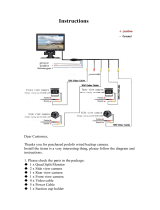
PACKAGE CONTENTS
This device consists of the following components.
In the event of any defect, contact the retailer where it was purchased.
1
Camera ECU box ...................................................................................................................1
2
Mounting brackets .................................................................................................................. 2
3
M5 × 12 mm hex bolt with washer .......................................................................................... 4
4
12P electrical system cable (0.5 m (1.64ft)) .............................................................................1
5
32P connection cable (0.2 m (0.66ft)) .....................................................................................1
6
40P connection cable (0.18 m (0.59ft)) ...................................................................................1
7
Installation Manual ..................................................................................................................1

HOW TO INSTALL
Installation Precautions
Be sure to read the Safety Precautions prior to installation and follow them throughout.
Installation Precautions
1 Camera ECU box
2-2 Mounting brackets
4-3 M5 × 12 mm hex bolts with washers
■
Precautions for Installing Mounting Brackets
2 Mounting bracket
3
M5 × 12 mm hex bolts with washers
Recommended torque : 0.6 N·m to 1.2 N·m
1
Camera ECU box
6 mm to 8 mm (Length protruding inside)
CAUTION
· If you should lose screws that come with the device, use either M5 × 12 mm hex bolts with washers or
screws of a length that protrude inside the ECU box to a depth of 6 mm to 8 mm.
Be sure to follow this precaution as using longer bolts may result in damage to the threads, prevent the
mounting bracket from getting tight enough and/or cause the screws to come out during operation of
the vehicle.
· The recommended torque for
3
M5 × 12 mm hex bolts with washers is 0.6 N·m to 1.2 N·m.
Be careful not to damage the threads by over-tightening the bolts.
WIRING AND CONNECTIONS
Wiring Precautions
Be sure to read the Safety Precautions prior to wiring and follow
them throughout.
Wiring Precautions
WARNING
Failure to do so may result in shock and/or
injury due to a short circuit.
It may also lead to damage to the system
components due to a short circuit.
• Disconnect the negative terminal of the battery before connecting the
cables.
Main
power supply
GND
Accesorry
power supply
CAM 1
カメラ 1
CAM-2
カメラ-2
CAM-3
カメラ-3
CAM-4
カメラ-4
40P connector
Electrical system
connector (12P connector)
16P connector
32P connector
Black
Black
Black
Black
Yellow
Yellow
Yellow
Black
Red
White
Black
White
Blue/White
Green/White
Purple/White
Brown/Red
Camera input terminal.
Connect if using CAM 1 / カメラ 1.
Camera input terminal.
Connect if using CAM-2 / カメラ-2.
Camera input terminal.
Connect if using CAM-3 / カメラ-3.
Camera input terminal.
Connect if using CAM-4 / カメラ-4.
Image OUT terminal (RCA connector).
Connect to monitor.
There are 2 identical connectors, and either can be used.
Backup power (DC +12V/24V)
Connect to the ⊕ power source that normal supplies power.
Ground (GND)
Connect to a metal part of the vehicle.
ACC power (DC +12V/24V)
Connect to ⊕ power supply that turnsON/OFF with the ignition key.
Spare signal
For use in situations like the door signal for a bus.
Connect to the ⊕ power supply that is supplied when the door is open.
Connect to the interface box (sold separately) used during calibration and setup.
Fuse 5A
Fuse 5A
Included:
5
32P connection cable
Included:
4
12P electrical system cable
Included:
6
40P connection cable
1 Camera ECU box
connector panel
L directional indicator signal
Connect to the ⊕ power supply that is supplied when the left directional indicator is
blinking.
R directional indicator signal
Connect to the ⊕ power supply that is supplied when the right directional indicator is
blinking.
Reverse signal (DC 10.8V to 28V)
Connect to the ⊕ power supply that is supplied when the gear shift is in the reverse
position.
Connect to the 16P connector of the
Camera ECU box.
Connect to a screen toggling switch
(RCB-210), which is sold separately.
CAUTION
CAUTION
Fuse
Fuse case
Terminal
on vehicle side
· When replacing a fuse, be sure to use one of the same
capacity.
· Putting in the wrong fuse may cause a fault, so check
the amperage of the fuses before replacing them.
When a fuse blows, follow the procedures below for preventing a short circuit and
replace the blown fuse with one of the same capacity.
Take care that the terminal on the vehicle side
does not touch any other metal part.
1. Disconnect the 12P electrical system cable.
2. Make sure all the wires are connected correctly.
3. After making sure everything is correct, replace the blown fuse with one of the
same capacity.
Camera Connections
For an outline of where to make camera connections, see the column for camera connection points for your system.
For details, such as on vehicle type or the cameras to connect for a given system specification, see the PDF manual in the
PC setup application. Please take care as a mistake in the camera connection points will prevent displaying the images cor-
rectly.
Camera Connection
Points by System
Camera System
2 Camera
3 Camera
4 Camera
2+2 Camera
Vehicle example
Truck (Right
steering wheel)
Truck (Left
steering wheel)
Shovel
Bus
Truck (Right
steering wheel)
Truck (Left
steering wheel)
Camera IN
Terminal
Harness Tag
CAM 1
1
Not connected
Not connected
Not connected
Front
OP:
Left-rear corner
OP:
Right-rear corner
CAM-2
-2
Not connected
Right
Right
Right
OP:
Right-rear corner
Right
CAM-3
-3
Left
Not connected
Left
Left
Left
OP:
Left-rear corner
CAM-4
-4
Rear
Rear
Rear
Rear
Rear
Rear
OP: Optional
Camera Connections
/