Page is loading ...

Assembly Guide of
LOC-Series Display Enclosure

Page 2
Table of Contents
1. General information: LOC-Series Display Enclosure ....................................................................... 3
2. Scope of delivery ............................................................................................................................. 3
3. Preparations for installation and comissioning ............................................................................... 4
4. Mounting the monitor ................................................................................................................... 10
5. Maintenance.................................................................................................................................. 13
5.1 General information on cleaning and maintenance ............................................................. 13
5.2 Changing the filters ............................................................................................................... 13
5.3 Miscellaneous ........................................................................................................................ 13
6. Technical data................................................................................................................................ 14
7. Technical drawings ........................................................................................................................ 14
4.1 Assembly for freestanding outdoor enclosure 32”-55” LOC-Series ..................................... 12
Assembly Guide of LOC-Series Display Enclosure

Assembly Guide of LOC-Series Display Enclosure Page 3
1. General information: LOC-Series Display Enclosure
The LOC-Series display enclosure is equipped with a sturdy metal casing and has both a ventilation
and a heating system. In outdoor use, it provides protection against humidity, wetness and
heat as well as vandalism and theft. The devices comply with the IP54/IP65 protection standard and
can be used in a temperature range from -20 ° to 40 ° C.
2. Scope of delivery
1) Housing (metal enclosure)
1 pc
2) Keys (coded – please record and store number)
2 sets
3) Beam to be attached to VESA fitting
2 pcs
4) Cable gland/ strain relief (25 mm) to feed- through ethernet cable
1 pc
5) Cable gland / strain relief (16 mm) to feed-through main connection (230 V/16A)
1 pc
6) Screws for fixing the beam to the monitor
1
7) Paper template for drilling
8) Standard mounting kit for wall assembly

Assembly Guide of LOC-Series Display Enclosure Page 4
3. Preparations for installation and comissioning
For the assembly you need the following tools:
1) Hammer drill
2) Spirit level and pencil
3) Dowels and screws to match wall structure
4) Small slotted screwdriver or phase tester
5) 10 mm jaw spanner for mounting/dismantling the monitor holder
6) 8 mm jaw spanner to fix door braces
7) Water pipe plier for screwing the cable glands
8) 4 mm Allen key wrench for mounting the supporting arms on the monitor
9) Open-end spanner (17 mm) to tighten the nuts (M10) on the hanger bolts
Please make sure that the desired installation location provides a 230 V power supply and internet
access option.
When mounting, please make sure that the respective wall has a sufficient load capacity for the
weight of the housing and display (for weight see data sheet). When choosing the location, we
recommend selecting positions with as much shade as possible or without intense sun exposure. This
increases the readability of the monitor in bright light conditions.
IMPORTANT! Prior to installation, please make sure that the power supply in the wall is
disconnected/turned off!
Mounting should be carried out by two persons.

Assembly Guide of LOC-Series Display Enclosure Page 5
Wall mounting of the metal housing
Starting with model series 2018, the housing is mounted directly and without wall bracket, using the
hanger bolts in the accessory package. Please check if the wall structure is suitable for this type of
mounting (other mounting systems are not included).
1) Use the supplied drilling template/wall plate to mark the drill holes on the mounting wall,
use a spirit level to position the plate. For the drilling template, please make sure to select
the correct model size!
2) Then drill the necessary holes in the wall using a hammer drill with a suitable drill. Make sure
that the holes are at least 10 cm away from the outer edge of the wall and are inserted
perpendicularly into the wall.
3) Insert dowels and hanger bolts with nuts in the wall, according to the following section
drawing. A standard mounting kit with the required mounting material is included in the
package.
For wall mounting of the housing, please use M10 hanger bolts with corresponding dowels and a
metric thread length LM of 50 mm. Depending on the type of wall, the total length I and LH must be
selected.
Furthermore, you need 2 body washers per bolt, e.g. M10, DIN 440R (ISO 7094), Da = 34 mm, Di = 11
mm, T = 3 mm, as well as 2 nuts (M10). For each hanger bolt, rotate one M10 nut onto the thread.
Then insert a body washer on the hanger bolt.
Make sure that the enclosure's distance from the wall is not less than 30 mm (red arrows on the
section drawing). Set a distance of ≥ 30 mm with the nut.
Lift the housing onto the hanger bolts, secure it against falling down and open the door. Place a
washer on each hanger bolt and tighten the housing with the nuts from inside.

Assembly Guide of LOC-Series Display Enclosure Page 6

Assembly Guide of LOC-Series Display Enclosure Page 7
Securing the door against accidental slamming or
impact while lying flat:
After opening, secure the door with the provided door
struts. For this purpose – as illustrated – position and
hook the lifting eye of the door strut on the bolt
between the nut and the housing edge and tighten the
nut to prevent the door strut from slipping out.
Please pay close attention to this procedure, otherwise
there is a high risk of crushing or injury by the door
slamming shut.
Lay down the housing with its back on a clean and padded surface. Unlock the door with the keys.
Closing direction of the lock:
Right side of door: Close in clockwise and
open in counter clockwise direction.
Left side of door: Open in counter clockwise
and close in clockwise direction.
When closing and opening the locks, gently press the
door against the housing. This will compress the
gasket and facilitate the closing process.
Open the door. ATTENTION! Please guide the door with your hand and hold firmly so it does not
move. Fold out the door struts (located on the narrow sides of the door on the inside) and insert the
holding loop - as shown in the picture - into the holder.

Assembly Guide of LOC-Series Display Enclosure Page 8
Installing the cable glands before mounting the housing
Screw the base body with the lock
nut as shown. Remove the
standard gasket. Pass the LAN
cable through. Place the slotted
gasket around the LAN cable and
insert it into the base body.
Provide sufficient cable length to
the PC. Screw and tighten the
union nut.
Screw the base body with the lock
nut as shown. Pass the power
cable through. Ensure sufficient
cable length to the connection
terminals. Screw and tighten the
union nut.

Assembly Guide of LOC-Series Display Enclosure Page 9
Prior to connecting the primary
circuit, please loosen the indicated
screws and remove the monitor
holder. After the power cable has
been plugged in, screw the
monitor holder tightly (torque
max. 5 Nm), two nuts per side.
Yellow = PE
Afterwards, you can continue clamping the power supply.
Connection terminals on primary
side from left to right:
Black = L
Blue = N
Connecting the cables
Setting up the power supply system
In order to connect the housing to the main supply, there is a power distribution terminal strip with 3
terminals (L: Grey, N: Blue, PE: Green/yellow) located inside of the device. Please note that the
connection may only be set up by a trained professional or an electrician.
When connecting, make sure that there is no voltage on the power supply line.
To get to the terminals, the monitor holder must be removed.
After power is connected, the monitor mount must be reinstalled.
1
1

Assembly Guide of LOC-Series Display Enclosure Page 10
4. Mounting the monitor
Please follow the instructions below to prevent damage to the monitor during installation:
First, please look for a clean and flat surface. When unpacking, make sure not to
scratch the surface of the screen and avoid pressure load on the surface. Therefore,
it is important that you thoroughly scan the storage area for objects such as screws
or dirt.
1) Take the monitor out of the cardboard box while keeping it up and always vertical.
2) Take the monitor arms and screw them back to the monitor with the supplied screws. Align
the arms centre to the horizontal axis of the monitor. Make sure that the distance between
the monitor edge and the mounting arm is the same at the top and bottom (averaged).
Observe the mounting direction of the mounting arms. They must be mounted in such a way
that the narrow-slit points upward. Otherwise the monitor cannot be hung.
3) Connect the required cables to the monitor.
a. HDMI-cable
b. Power cable
4) Now, with the cables connected, insert the monitor into the housing. A corresponding device
for this purpose is attached on the inside of the housing.

Assembly Guide of LOC-Series Display Enclosure Page 11
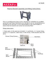
The picture shows the inside of the housing with the monitor holder (media player provided by
customer, not included!)
Tilt adjustment /distance setting:
The tilt of the monitor can be
adjusted by loosening the nuts.
The distance between the monitor
front and the inner side of the glass
is also adjusted. The prescribed
distance is 14 - 18 mm (torque max.
5 nm), two nuts per side.
Gland for power
cable
Gland for RJ45
Heater Moun ng holes Moun ng bracket for monitor Moun ng holes Heater

Assembly Guide of LOC-Series Display Enclosure Page 12
4.1 Assembly for freestanding outdoor enclosure 32”-55” LOC-Series
The LOF-Series (stand) is an optional freestanding floor mount to the LOC-Series. Following the
assembly steps for the freestanding outdoor enclosure 32"-55" LOC-Series:
Take the two columns (blue) and screw them together with the backplate (red).
The cables can be inserted in both columns.
Take the freestanding unit and mount it perpenticular in both axis onto the fundament.
(Anchors and screws are not scope of delivery)
Please refer to the installation guide of the enclosure how to mount the screwed cable glands.
Take the enclosure and screw it on the freestanding unit by using the delivered screws (Allen M8).
Handle the enclosure like it is documented in the installation manual of the enclosure.
Put the cable through the glands.
Take the cover plate (green) and screw it on the backplate (red). Screws (Allen M6) are delivered in
screwpack.
Start the installation of the power cable, Monitor etc. as refered in the installation manual of the
enclosure.

Assembly Guide of LOC-Series Display Enclosure Page 13
5. Maintenance
5.1 General information on cleaning and maintenance
Clean the glass at regular intervals to ensure a clear view of the display. To do this, use a soft cloth,
lukewarm water and mild soap or glass cleaner. Wipe the glass with a dry soft cloth to avoid lime
stains. Do not clean the pane in case of excessive heating, which could lead to stress cracks. Do not
use sharp or hard objects, they can damage the pane.
Do not use high-pressure cleaning devices or a highly bundled water jet during cleaning operations.
Do not use abrasive cleaners or cleaning utensils.
5.2 Changing the filters
Check the filter mat at regular intervals regarding the degree of contamination. If the filter mat is
dirty, it must be replaced. This should only be done by qualified personnel.
5.3 Miscellaneous
Make a visual inspection of the housing and the display at regular intervals. Due to vandalism or
extreme environmental influences (e.g. very high dust volume, high salinity of the air) the housing
can be damaged or affected.

Assembly Guide of LOC-Series Display Enclosure Page 14
6. Technical data
7. Technical drawings
lllustrated models with wall mount. Models without a wall bracket are identical when assembled.
When installed in a wall niche, make sure that there is a clearance of at least 50 mm above, left and
right around the housing. At the bottom, the space should be 100 mm, so that the keys can be
inserted in
order to lock the enclosure. The informations given represent minimum dimensions,
ensuring sufficient air circulation around the housing.
All housings comply with CE standard. EMC type test was carried out for the housings.
Product description
LOC-32 LOC-43 LOC-55
Screen diagonal 81 cm (32") 109 cm (43") 140 cm (55")
Dimensions (WxHxD) enclosure / housing 89,8 x 59,3 x 17,0 cm 114,1 x 72,9 x 20,0 cm 141,0 x 88,1 x 20,0 cm
Color DB 703 (anthracite) DB 703 (anthracite) DB 703 (anthracite)
Coating housing fine structure fine structure fine structure
Operating temperature -20 °C ~ +40 °C -20 °C ~ +40 °C -20 °C ~ +40 °C
Protection class IP65 (Front) / IP54 (Backside) IP65 (Front) / IP54 (Backside) IP65 (Front) / IP54 (Backside)
Typ. energy consumption housing Ø 60 - 70 Watt Ø 65 – 75 Watt Ø 70 – 80 Watt
Energy consumption housing (min/max, all
components on)) without monitor/PC
Min. / Max: 25 / 275 Watt Min / Max: 25 / 290 Watt Min / Max: 30 / 305 Watt
Weight housing 30,5 Kg 41,5 Kg 62 Kg
Enclosure operating time 18/7 18/7 18/7
Power supply 230 V 230 V 230 V

Page 1
Technical drawing: 32" display enclosure
224 450
449
170
898
698
100
Assembly Guide of LOC-Series Display Enclosure

Page 1
Technical drawing: 43" display enclosure
210.5 720
570.5
200
1141
941
100
Assembly Guide of LOC-Series Display Enclosure

Page 1
Technical drawing: 55" display enclosure
100
1410
1210
296 818
705
200
Assembly Guide of LOC-Series Display Enclosure
Gland for power cable
Gland
for RJ45

Page 18
Technical drawing: LOF-Series Stand
Assembly Guide of LOC-Series Display Enclosure
Ø14mm
/