Page is loading ...

REVISION A
Form No. 3312890.000 5/17
(French 3312921.000_A)
©2017 Dometic Corporation
LaGrange, IN 46761
INSTALLATION
INSTRUCTIONS
USA
SERVICE OFFICE
Dometic Corporation
1120 North Main Street
Elkhart, IN 46514
CANADA
Dometic Corporation
46 Zatonski, Unit 3
Brantford, ON N3T 5L8
CANADA
For Service Center
Assistance:
Visit:
www.eDometic.com
RECORD THIS UNIT INFORMATION FOR
FUTURE REFERENCE:
Model Number
Serial Number
Date Purchased
This manual must be read and
understood before installation,
adjustment, service, or mainte-
nance is performed. This unit must
be installed by a qualied service
technician. Modification of this
product can be extremely hazard-
ous and could result in personal
injury or property damage.
Lire et comprendre ce manuel avant de
procιder ΰ l'installation, ΰ des rιglages,
de l'entretien ou des rιparations.
L'installation de cet appareil doit κtre
effectuιe par un rιparateur qualiι.
Toute modication de cet appareil
peut κtre extrκmement dangereuse et
entraξner des blessures ou dommages
matιriels.
Important: These Instructions must
stay with unit. Owner read carefully.
Model
945(XX)(YY).000#
FRTA
895300(X).400#
Hardware
8953001.400# Basement Hardware
8953002.400# Standard Hardware
FOR
945(XX)(YY).(X)00(#)
Fabric Roller Tube Assembly
Residential Patio Awning

2
895300(X).400# Residential Patio Awning Installation Instructions
SAFETY INSTRUCTIONS
This manual has safety information and instruc-
tions to help users eliminate or reduce the risk
of accidents and injuries.
RECOGNIZE SAFETY INFORMATION
This is the safety-alert symbol. When you see
this symbol in this manual, be alert to the poten-
tial for personal injury.
Follow recommended precautions and safe op-
erating instructions.
UNDERSTAND SIGNAL WORDS
A signal word , WARNING OR CAUTION is
used with the safety-alert symbol. They give the
level of risk for potential injury.
indicates a potentially hazard-
ous situation which, if not avoided, could result
in death or serious injury.
indicates a potentially hazard-
ous situation which, if not avoided, may result in
minor or moderate injury.
used without the safety alert
symbol indicates, a potentially hazardous situa-
tion which, if not avoided, may result in property
damage.
Read and follow all safety information and in-
structions.
REQUIRED TOOLS:
(1) Cordless Drill
(1) Socket Bit Set
(1) Drill Bit Set
(1) Hammer
(1) Wire Strippers
(1) Wire Cutters
(1) Jig Saw or Hand Saw and Chisel
(1) Torsion Winder Kit (3308334.006U)
REQUIRED PARTS: (Packed with each Hardware Assembly)
8953001.400# & 8953002.400# Hardware
(4) Mounting Bracket
(8) #14-10 x 1-1/2” Hex Head Screw
(2) .25” Split Lock Washer
(8) 3/16" X 1" Oscar Rivets
(2) #6-20 x .44” Hex Washer Head Self Drilling Screw
(2) 1/4”- 20 x 3/4” Hex Head Bolts
Note: For service parts go to www.eDometic.com and
click the link “Service Parts”. Enter your product model
number to view service parts available.
Important: Read and understand ALL of the follow-
ing steps before beginning installation.
Application
The Dometic Awning is designed and intended for use on
homes.
Important: Structural backing is required where
mounting screws will be installed on home wall for
securing top mounting brackets and back channels.
Important: Follow the Minimum distance dimensions
requirements from awning rail to door. Mounting height
depends on awning type and length. Insure sufcient
room is available before starting installation.
Hardware Model Minimum Distance
8953001.400# 17”
8953002.400# 12”
When the door falls in the center of the awning, add 2” to
these distances.
Installaon Height: This is the center to center distance
of mounng holes in the top mounng bracket and the
back channel. See Specicaon chart and illustraons
on page 3.
Dometic, LLC reserves the right to modify appearances
and specications without notice.

3
895300(X).400# Residential Patio Awning Installation Instructions
C
B
A
K
H
J
D
G
L
F
E
G
K
H
B
C
D
J
A
895300X.400# Residential Patio awning Hardware
FIG. 1
Top Casting
FIG. 2
L Bracket
Back Channel
Nylon Tie
Front
Channel
Bolt & Lock
Washer
Specication Chart
8953001.400# 8953002.400#
A 62 3/4” 66-7/8”
B 60-3/4” 64-1/4”
C 61-1/2” 65”
D 3/4” 3/4”
E 60-1/8” 63-5/8”
F 62-1/8” 65-5/8”
G 31” 32-7/8”
H 5/8” 65-5/8”
J 3/8” 3/8”
K 1/4” 1/4”
L 35-1/4” N/A
A= Overall length of hardware
B= Minimum mounting distance center to center on
mounting holes.
C= Maximum mounting distance center to center on
mounting holes.
D= Distance between mounting holes in bracket.
E= Distance from top edge of mounting bracket to cen-
ter of hole for wire harness.
F= Back channel length.
G= Distance from top edge of mounting bracket to cen-
ter of middle mounting hole on back channel.
H= Distance front channel guard extends past back
channel.
J= Distance from top edge of top bracket and center of
rst mounting hole.
K= Distance between edge of back channel and bottom
mounting holes.
L= Distance from top edge of mounting bracket to
center of optional middle mounting holes on back
channel.
Installation Instructions
Installation of Dometic Awnings will briey re-
quire three people. Use the following procedure
to assure a properly installed and properly func-
tioning awning.
A. Secure FRTA to Hardware
1. Carefully lay the fabric roller tube assembly on
a clean, well padded “V” trough to prevent fabric
and/or roller cover damage. Remove the hard-
ware from the packaging and place the arm pre-
wired for the motor on the right side. The left arm
is not pre-wired for the motor.
Personal Injury Hazard. Rapid casting spin
off will occur if not controlled. Do not re-
move cotter pin in end cap until top casting
is secured to hardware. Failure to heed this
warning could cause severe personal injury.
Personal Injury Hazard. Hardware arms are
spring loaded. Rapid arm extension will oc-
cur if tie is removed before top casting is se-
cured to hardware. Failure to heed this warn-
ing could cause severe personal injury.
2. Secure each front channel to top casting of the
FRTA. See FIG. 2. Slide top nylon ties down arm
approximately 24 inches to allow hardware to
open far enough to insert top casting into front
channel. Do not remove nylon ties at this time.
The gas shocks on arm assemblies are pressur-
ized and will spring open if not controlled.
3. Using one (1) 1/4”-20 x 3/4” hex head bolt and
one (1) 0.25 split lock washer secure both top
castings to the right and left front channels. See
FIG. 2.
4. Remove cotter pin from LH end cap.

4
895300(X).400# Residential Patio Awning Installation Instructions
Personal Injury Hazard. Rapid casting spin
off and rapid arm extension will occur if they
are not controlled. Before separating torsion
from hardware, the torsion must be pinned
through end cap and hardware arms must
be bound. Failure to heed this warning may
cause severe personal injury or property
damage.
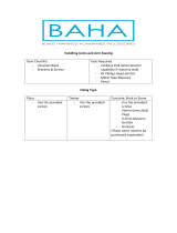
B. Install Backer Boards
1. Prepare the mounting area
a. Remove siding sections. See FIG. 3
b. Install back boards in the cut out section
making sure the thickness of the back boards
are ush with the peaks of the siding. The top
back board width should be a minimum of 6"
and the minimum length must be longer than
the length of the awning
Secure backer boards to studs using two
nails per wood stud. See FIG. 4 and 5.
FIG. 5
a. Seal all edges and nail area with clear sili-
cone sealer.
C. Install Awning Rail
1. Prepare the mounting area.
a. Before securing the awning rail to the top
backer board, make sure the nails secur-
ing the back board to the studs do not inter-
fere with the awning rail. Leave a minimum
of two inches between the top edge of the
backer board and the backer board mounting
screws. See Fig. 6
In case there is not enough room or there are
obstacles making it impossible to walk the
fabric through a mounted awning rail, slide
the rail on the FRTA. Skip step b. and go to
step D. (Install Fabric in Awning Rail).
b. Level the awning rail and install to top
backer board using #6 screws. See Fig. 6
FIG. 3
Wood
Frame
Studs
Bottom Sections
Top Section
FIG. 4
6"
min.
6"
min.
Nails
Nails
Nails
FIG. 6
2"
#6-20 X .5"
Screws
D. Install Fabric in Awning Rail
1. Prepare the awning rail to accept the awning fab-
ric.
a. Select the end from which the awning shall
be fed, then widen that end with a at screw-
driver and le off any sharp edges. See FIG.
7A.

5
895300(X).400# Residential Patio Awning Installation Instructions
Before
After
Arm
Asm.
Nylon
Tie
Awning
Rail
Fabric
Roller Tube
Assembly
Nylon
Tie
FIG. 7A
+
+
+
+
+
+
FIG. 8A
FIG. 8B
8953002 Standard & 8953001 Basement Hardware
Top Brkt
Bolt, lock
Washer, &
Spacer
Front
Channel
Top Brkt
2. Unwind fabric one revolution before feeding aw-
ning fabric into awning rail. This will allow enough
space between side wall and awning hardware to
connect wires in Step F.
Important: Do not remove more than one revolution
of fabric.
3. Slide the rail on the FRTA.
4. With one person grasping each arm assembly,
carefully lift the entire assembly to an upright po-
sition. Rest arms on two ladders see FIG. 7B.
Important: Keep the two arm assemblies parallel to
each other to avoid excessive twisting and possible
damage to the assembly.
5. Go to step C.1.b. (Install Awning Rail)
E. Top Mounting Bracket Installation
1. (8953001 Basement & 8953002 Standard Hard-
ware) Secure Top mounting Brackets
a. After the complete awning assembly has
been threaded into the awning rail, check that
its position allows for solid mounting of the
top mounting brackets and the back chan-
nels. Also insure that the back channels are
in the desired location (not restricting use of
doors, access doors, windows, etc.)
Important: Structural backing is required where
mounting screws will be installed through sidewall for
securing top mounting brackets.
b. Place both top brackets in position directly
under the awning rail as shown in FIG. 8B.
The motorized arm assembly is always in-
stalled on the right end of the awning.
Top bracket must be installed parallel with the
awning rail. Using the outside bracket hole as
a guide, pre- drill a 3/16” hole for mounting
screw. Drill a 7/32” hole if drilling into steel.
Install outside top mounting bracket using
one (1) #14-10 x 1-1/2” hex head screw. Seal
where the screw enters the back board with
clear silicon sealer. Repeat this procedure for
opposite side.
The arm assemblies must be controlled
while the top mounting brackets are being
installed. When the weight of the FRTA is no
longer supported, the downward force could
cause the arm assembly to swing side ways
and may damage the sidewall if not con-
trolled.
F. Power Supply (3312910.007) Installation
1. The 331291.007 power supply is designed to de-
liver continuous trouble – free operation.
a. First, decide on location of the power sup-
ply keeping it close to the awning and outlet.
Hang box by using keyhole mounting holes
(will t #8 or #10 screws) located at the back
of the power supply box. See FIG. 9A
b. Connect terminal block on the bottom of the
unit to the awning connections provided. Cut
wire coming out of the awning arm to desired
length and strip wires. Use spade terminals
and connect the red wire to the positive (+)
and black wire to the negative (-) terminal
block labeled on the power supply. See FIG.
9B
c. Plug the AC plug into a 120V AC outlet. See
Fig. 9A
d. Use the switch on the top of the unit to control
the awning as desired.
Arm
Asm.
FIG. 7B

6
895300(X).400# Residential Patio Awning Installation Instructions
Motor
Arm
FIG. 11
Do not place unit on or near to sources of
heat. Incorrect wiring may result in serious
damage to both power supply and equip-
ment wired to power supply. Power supply
service should be done at factory. Do not
use an extension cord.
Important: The awning is now operational. Complete
Steps G & H.
G. Back Channel Installation
Important: Flat solid Backer board (1/2” thick)
is required where #14-10 x 1-1/2” Hex Head Screw
(3104499.003) (supplied) will be installed through wall
for securing back channels.
1. Open awning as required to secure back chan-
nel.
2. Align the back channel so it is square with the
wall and the FRTA. A door or window frame can
be used to measure from. See FIG. 10.
5. Seal where the screws enter the wall with clear
silicon sealer.
6. To install screws on the inside top mounting brack-
ets it will be necessary to pull the FRTA away from
the side wall approximately 12”. Remove nylon
ties wrapped around the front and back channels.
See FIG. 8B. Grasp the front channel and slowly
pull it away from the sidewall. Predrill hole as in
previous step and install one (1) #14-10 x 1-1/2”
hex head screw. Repeat this procedure for oppo-
site side. Seal where screw enters the wall with
clear silicon sealer.
• Connect the motor wire to the factory pre-
wired hardware wiring. See FIG. 11.
FIG. 9A
FIG. 10
Power
Supply
AC
Plug
Align
Square
#14-20
X 1-1/2"
Screws
3. Drill four (4) 3/16” holes through the outside wall
using the holes on the back channel as a guide.
See FIG. 1.
4. Secure each back channel to wall with four (4)
#14-10 x 1-1/2” Hex Head Screw (3104499.003)
provided, 2 screws at middle and 2 screws at
bottom. Be careful not to pinch or damage motor
wire when securing channel to wall. See FIG. 9.
Depending on your model, wire covers may need
to be removed to access back channel holes.
Important: Flat solid structure backing (1/2” thick) is
required if using wood screws (supplied).
FIG. 9B
Spade
Terminals
Terminal
Block
Strip Wires

7
895300(X).400# Residential Patio Awning Installation Instructions
FIG. 12
2"
Awning
Rail
#6 X .44"
TEK Screw
Fabric
Cotter Pin
Insert Cotter Pin All The
Way Through End Cap
And Hole In Torsion Rod
Pin
Slots In
End Cap
Left Hand Torsion Shown
Turn FRTA or Top Casting To
Align Slots In End Cap With Pin
FIG. 13
Crank
Pin
Adapter
Top
Casting
End Cap
1/4-20 X 1/2" Hex
HD Mach. Set
Screw (Thru Rear)
FIG. 14
F. Initial Awning Adjustment
Important: Rapid cycling of the awning (opening &
closing) can cause the motor to overheat. Allow 2-3
minutes between cycles.
1. Cycle the awning four or ve times to check fabric
alignment and to make sure the hardware is nest-
ing properly. If there is a misalignment, adjust the
arm by loosening the upper mounting bolts and
move the bracket accordingly. Cycle the awning
again to check the alignment. See User’s Guide
for opening and closing instructions.
Note: Press rocker switch until awning is fully extended
or retracted. If switch is released awning should stop ex-
tending or retracting. If not, more than one wrap of fabric
was unwound during installation. See Section H for cor-
rections.
2. When satised with the alignment, secure fabric
roller cover by driving a #6-20 x .44” TEK screw
through the rail and into the fabric rope. See FIG.
12 for screw location. Repeat steps 1 and 2 to
align the opposite end. The installation is now
complete and ready for use.
G. Close and Secure Awning
1. If awning will not be used after installation, close
and secure. See User’s Guide for closing and se-
curing instructions.
H. Increasing Turns on Left Hand Torsion
Use extreme care. Springs under tension are
dangerous. If not controlled they will unwind
quickly. Keep hands and clothing clear of
top casting, as personal injury may result.
Note: Complete the following steps on a step ladder with
the FRTA extended two turns from the awning rail.
Severe injury can result from the rapid
spin-off of the top casting. NEVER use bare
hands to handle a top casting under spring
tension.
1. Before the left arm assembly is removed the tor-
sion must be pinned to prevent uncontrolled un-
winding of the spring.
a. Turn top casting or FRTA until the pin is paral-
lel with the two slots in the end cap. See FIG.
13.
b. To pin the left hand torsion insert a 7/64” x
2-3/4” cotter pin through the end cap and tor-
sion rod. Put a piece of tape over the head of
the cotter pin to prevent it from dropping out.
See FIG. 13.
c. Insert a wood block, between front and back
channel to space the FRTA 2 - 3 inches from
the coach. Push arm assembly closed. Wrap
a nylon wire tie around arm to keep it from
extending.
d. Remove Hex Head 1/4-20 x 3/4” screw that
attaches arm assembly to top casting.
Lift casting out of arm assembly.
e. Attach crank adapter (3308335.011) with 1/4-
20 screw and pin crank (3308335.003) as
shown on FIG. 14. (Crank & adapter supplied
in 3308334.006U Torsion Winder Kit.)

8
895300(X).400# Residential Patio Awning Installation Instructions
f. Keep a tight hold onto the crank while the cot-
ter pin is pulled out of the end cap.
g. Slowly unwind spring tension by allowing the
spring to unwind counter clockwise. Torsion
will want to unwind by itself. Caution should
be taken to prevent rapid unwind.
h. Once spring is free, position of top casting
should be noted for starting position.
i. Slowly wind the spring tension clockwise
eight (8) complete turns.
j. Reinsert cotter pin through end cap and tor-
sion rod. See FIG. 13.
k. Remove crank from top casting in arm as-
sembly.
l. Reinsert top casting into arm assembly.
m. Replace hex head 1/4-20 x 3/4” screw that
attaches arm assembly to top casting.
n. Remove nylon tie and wood block.
o. Remove cotter key before attempting to oper-
ate awning.
p. Cycle the awning again and verify awning
stops extending when switch is released.
/