DURKOPP ADLER 580 User manual

Type
User manual
1. Verwendung des Teilesatzes
Der Teilesatz “Lasermarkierung” ist für Augenknopflochmaschinen der Klasse 559 und 580 vorgesehen.
2. Inhalt des Teilesatzes
Der Teilesatz besteht aus folgenden Bauteilen:
1 x Laser
2 x Befestigungsschelle
1 x Druckstück
1 x Zylinderschraube
1xHalter
1 x Linsenkopfschraube
1 x Leiterplatte
2 x Abstandsbolzen
2 x Zylinderschraube
4 x Kabelbinder
3. Lasermarkierung montieren
3.1 Fingerschutz demontieren
Schrauben 1 herausschrauben und Halter 2 abnehmen.
Schrauben 3 herausschrauben und Fingerschutz 4 abnehmen.
Ausgabe/Edition:
02.2008
Aenderungsindex
Rev. index: 01.0
Printed in Germany
Anbauanleitung für Teilesatz 0580 590564
Lasermarkierung
Fitting instruction for the set of parts 0580 590564
Laser marking
Teile-Nr./ Part-No.:
0791 580701
Blatt: von
Sheet: 1 from 8
21 43
3.2 Lasermarkierung vormontieren
Laser 1 mit Schelle 3, Druckstück 2 und Schraube am Halter 5 festschrauben.
Zuleitung 6 mit Schelle 7 am Halter festschrauben.
Fingerschutz 4 montieren.
3.3 Lasermarkierung anschrauben
Halter 5 mit Lasermarkierung am Oberteil 8 anschrauben.
Anbauanleitung für Teilesatz 0580 590564
Lasermarkierung
Fitting instruction for the set of parts 0580 590564
Laser marking
Teile-Nr./ Part-No.:
0791 580701
Blatt: von
Sheet: 2 from 8
Ausgabe/Edition:
02.2008
Aenderungsindex
Rev. index: 01.0
Printed in Germany
54321
76
85
3.4 Laseranschlussleitung verlegen.
Handrad 1 abschrauben.
Riemenschutz 2 abschrauben.
Spannungsplatte 3 abschrauben.
Laserleitung 4 an der Zuleitung 5 des Bedienfeldes entlang legen und mit drei Kabelbindern
befestigen.
Laserleitung im Oberteil verlegen und aus der Aussparung 6 herausziehen.
Spannungsplatte 3 wieder aufschrauben.
Anbauanleitung für Teilesatz 0580 590564
Lasermarkierung
Fitting instruction for the set of parts 0580 590564
Laser marking
Teile-Nr./ Part-No.:
0791 580701
Blatt: von
Sheet: 3 from 8
Ausgabe/Edition:
02.2008
Aenderungsindex
Rev. index: 01.0
Printed in Germany
213
43
45
45
46
3.5 Leiterplatte montieren, Leitungen anschließen und Laser ausrichten
Leiterplatte 1 mit zwei Schrauben 2 und zwei Abstandsbolzen am Gehäuse festschrauben.
Laserleitung 3 um die Leiterplatte herum verlegen und den Stecker 4 auf der Leiterplatte
aufstecken.
Stecker der Anschlussleitung 5 (Leitung X410) auf der Leiterplatte aufstecken.
Riemenschutz 7 und Handrad 6 montieren.
Nähautomaten einschalten.
Ein Knopfloch nähen.
Laser so ausrichten, dass seine Markierung 8 genau in der Mitte des Knopfloches steht.
Anbauanleitung für Teilesatz 0580 590564
Lasermarkierung
Fitting instruction for the set of parts 0580 590564
Laser marking
Teile-Nr./ Part-No.:
0791 580701
Blatt: von
Sheet: 4 from 8
Ausgabe/Edition:
02.2008
Aenderungsindex
Rev. index: 01.0
Printed in Germany
5143
21
76
8
1. Use of the set of parts
The set of parts “laser marking” is designed for eyelet buttonhole automats of the classes 559 and 580.
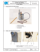
2. Content of the set of parts
The set consists of the following parts:
1xlaser
2 x fastening clip
1 x thrust piece
1 x cylinder head screw
1 x holder
1 x fillister head screw
1 x printed circuit board (PCB)
2 x spacer bolt
2 x cylinder head screw
4xcabletie
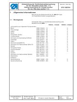
3. Fitting the laser marking
3.1 Removing the finger protection
Unscrew the screw 1 and take off the holder 2.
Unscrew the screws 3 and take off the finger protection 4.
Anbauanleitung für Teilesatz 0580 590564
Lasermarkierung
Fitting instruction for the set of parts 0580 590564
Laser marking
Teile-Nr./ Part-No.:
0791 580701
Blatt: von
Sheet: 5 from 8
Ausgabe/Edition:
02.2008
Aenderungsindex
Rev. index: 01.0
Printed in Germany
21 43
3.2 Preparing the laser marking for mounting
Fasten the laser 1 to the holder 5 by using the clip 3, the thrust piece 2 and screw.
Fasten the cable 6 to the holder by using the clip 7.
Fix the finger protection 4.
3.3 Fixing the laser marking
Screw the holder 5 with the laser marking to the machine head 8.
Anbauanleitung für Teilesatz 0580 590564
Lasermarkierung
Fitting instruction for the set of parts 0580 590564
Laser marking
Teile-Nr./ Part-No.:
0791 580701
Blatt: von
Sheet: 6 from 8
Ausgabe/Edition:
02.2008
Aenderungsindex
Rev. index: 01.0
Printed in Germany
54321
76
85
3.4 Laying the cable connection for the laser
Unscrew the hand wheel 1.
Unscrew the belt guard 2.
Unscrew the tension plate 3.
Lay the laser cable 4 alongside the cable 5 of the control panel and fix it with three cable ties.
Lay the laser cable inside the machine head and pull it out of the keyway 6.
Refit the tension plate 3.
Anbauanleitung für Teilesatz 0580 590564
Lasermarkierung
Fitting instruction for the set of parts 0580 590564
Laser marking
Teile-Nr./ Part-No.:
0791 580701
Blatt: von
Sheet: 7 from 8
Ausgabe/Edition:
02.2008
Aenderungsindex
Rev. index: 01.0
Printed in Germany
213
43
45
45
46
3.5 Fitting the PCB, connecting the cables and adjusting the laser
Screw the PCB 1 by using two screws 2 and two spacer bolts to the housing.
Lay the laser cable 3 around the PCB and put the plug 4 onto the the PCB.
Put the plug of the connecting cable 5 (cable X 410) onto the PCB.
Refit the belt guard 7 and the hand wheel 6.
Switch on the sewing automat.
Sew a buttonhole.
Adjust the laser so that the marking 8 appears right in the middle of the button hole.
Anbauanleitung für Teilesatz 0580 590564
Lasermarkierung
Fitting instruction for the set of parts 0580 590564
Laser marking
Teile-Nr./ Part-No.:
0791 580701
Blatt: von
Sheet: 8 from 8
Ausgabe/Edition:
02.2008
Aenderungsindex
Rev. index: 01.0
Printed in Germany
5143
21
76
8
  • Page 1 1
  • Page 2 2
  • Page 3 3
  • Page 4 4
  • Page 5 5
  • Page 6 6
  • Page 7 7
  • Page 8 8

DURKOPP ADLER 580 User manual

Type
User manual

Ask a question and I''ll find the answer in the document

Finding information in a document is now easier with AI

in other languages