Page is loading ...

DK S N P GR
➔ www.docuthek.com
D GB F NL I E
TR CZ PL RUS H
© 2016 Elster GmbH · Edition 02.16
Cert. version 02.16
Safety
Please read and keep in a safe place
Please read through these instructions
carefully before installing or operating. Following the
installation, pass the instructions on to the opera-
tor. This unit must be installed and commissioned
in accordance with the regulations and standards
in force. These instructions can also be found at
www.docuthek.com.
Explanation of symbols
• , 1 , 2 , ... = Action
▷ = Instruction
Liability
We will not be held liable for damage resulting from
non-observance of the instructions and non-com-
pliant use.
Safety instructions
Information that is relevant for safety is indicated in
the instructions as follows:
DANGER
Indicates potentially fatal situations.
WARNING
Indicates possible danger to life and limb.
CAUTION
Indicates possible material damage.
All interventions may only be carried out by qualified
gas technicians. Electrical interventions may only be
carried out by qualified electricians.
Conversion, spare parts
All technical changes are prohibited. Only use OEM
spare parts.
Contents
Operating instructions
D
GB
F
NL
I
E
GB-1
0251456
Translation from the German
UV sensor UVS 5
UV sensor UVS 5 .......................1
Contents ..............................1
Safety.................................1
Checking the usage .....................2
Installation ............................2
Replacement...........................
Wiring ................................
Maintenance ...........................4
Replacing the UV tube ....................4
Assistance in the event of malfunction .....4
Technical data .........................5
Logistics ..............................5
Certification ...........................6
Eurasian Customs Union ..................6
Contact ...............................6
Safety
Contents

GB-2
D
GB
F
NL
I
E
Checking the usage
UV sensor for intermittent operation for flame
control on gas burners in conjunction with Elster
Kromschröder automatic burner control units (IFS,
IFD, PFS, PFD), flame detectors (IFW, PFF) or burner
control units (BCU,PFU).
This function is only guaranteed when used within the
specified limits– see page5 (Technical data). Any
other use is considered as non-compliant.
Type code
Code Description
UVS UV sensor
5 Series 5
G1
Electrical connection:
M20 cable gland
Part designations
4
3
2
1
2
3
4
6
7
8
5
1 M20 cable gland
2 Housing
Spring force terminals
4 Sensor head
5 Positioning aid
6 Sticker
7 UV tube
8 Bracket
Installation
CAUTION
Use UV sensor only in conjunction with Elster
Kromschröder automatic burner control units,
flame detectors or burner control units in order to
avoid damage.
▷
It is preferable to install the unit inclined from
above or in the horizontal.
< 400mm
(16”)
▷
Distance between UVS and flame: max.400mm
(16").
▷ The UV sensor may only be exposed to the UV
light of its own flame. It should be protected
from other sources of ultraviolet light, e.g. neigh-
bouring flames (this must be observed when
monitoring pilot and main burners in particular),
ignition sparks, arcs from welding devices or
lamps emitting ultraviolet light.
▷
Avoid exposing the UV sensor viewing openings
to direct sunlight.
▷
Protect the viewing openings against dirt and
moisture.
4,5
N 24
1818
21
4
5
3
Direct at the flame from the front or side.
Positioning aid
to allow sim-
ple alignment
when replac-
ing sensors/
tubes.

GB-3
D
GB
F
NL
I
E
Replacement
WARNING
Electric shocks can be fatal! Before working on
possible live components, ensure the unit is discon-
nected from the power supply.
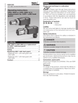
Replacing the old UVS5 with the new
UVS5G1
▷
The old UVS5 (with non-detachable PVC cable)
can be replaced with the new UVS5G1 (with
cable gland and spring force terminals).
UVS 5 UVS 5G1
B
A
▷
Bracket A and clamping collar B from the old
UVS5 can be used to secure the new UVS5G1.
1 Disconnect the system from the electrical power
supply.
2 Shut off the gas supply.
4 5
1 3
Clamping
collar
Old UVS 5
6 Attach the clamping collar from the old UVS5
to the new UVS5G1.
7 Fit the new UVS5G1 with the clamping collar in
the bracket of the old UVS5.
8 Direct UVS5G1 at the flame from the front or
side.
9 Tighten the bolt of the clamping collar to secure
the UV sensor in the required position.
▷ Electrical connection of the new UVS5G1, see
page 3 (Wiring).
Wiring
WARNING
Electric shocks can be fatal! Before working on
possible live components, ensure the unit is discon-
nected from the power supply.
▷ Connection cable:
– Use in accordance with local regulations.
– Lay individually and, if possible, not in a metal
conduit.
– Do not lay together with ignition cable but lay
them as far apart as possible.
– M20 cable gland is designed for cable diameters
of 7 to 13mm.
– Spring force terminals for wire cross-sections
>0.2mm² to ≤1.5mm² (AWG24 to AWG16).
– Max. cable length in accordance with the speci-
fications for automatic burner control units IFS,
IFD, PFS, PFD, flame detectors IFW, PFF or
burner control units BCU,PFU.
▷
External electrical interference must be avoided.
1 Disconnect the system from the electrical power
supply.
2 Shut off the gas supply.
2
3
4
1
2
3
4
1
2
3
4
2 31
4
UVS
4321
PE
–
+
µA
Wiring, see IFS,
IFD, PFS, PFD,
IFW, PFF, BCU or
PFU connection
diagram.
▷ Flexible wires without wire end ferrules can also
be connected to the spring force terminals. To
insert a flexible wire, the terminal must be opened
using the push-button.

GB-4
D
GB
F
NL
I
E
Maintenance
Replacing the UV tube
WARNING
Electric shocks can be fatal! Before working on
possible live components, ensure the unit is discon-
nected from the power supply.
CAUTION
Do not touch the replacement UV tube with bare
fingers.
▷ The sensor tube must be replaced after approx.
10,000 operating hours (approx. 1year).
▷ Spare parts (tube, sticker, seal), see www.part-
detective.de
1 Disconnect the system from the electrical power
supply.
2 Shut off the gas supply.
2 53
6
4
Use new
sticker.
Insert tube
with seal.
Assistance in the event of
malfunction
WARNING
– Electric shocks can be fatal! Before working
on possible live components, ensure the unit
is disconnected from the power supply.
– Fault-clearance must only be undertaken by
authorized trained personnel!
– Do not carry out repairs on the UV sensor on
your own as this will cancel our guarantee. Un-
authorized repairs or incorrect electrical con-
nections can cause the UV sensor to become
defective. In this case, fail-safe operation can
no longer be guaranteed.
– (Remote) resets may only be conducted by
authorized trained personnel with continuous
monitoring of the burner to be repaired.
– Safe operation only in conjunction with Elster
Kromschröder automatic burner control units,
flame detectors or burner control units.
• Measure the current in the flame signal cable
(connect the positive pole of the measuring in-
strument to the cable from the automatic burner
control unit and the negative pole to the cable
from the UV sensor).
UVS
1
4
3
2
PE
–
+
µA
▷
The measured direct current must be greater
than 1µA (typically 20µA).
? Fault
! Cause
• Remedy
? A direct current is flowing, but no flame
present.
! The UV sensor is influenced by the flames of
other burners, e.g. by reflection on the furnace
walls.
• Position the sensor so that it can only “view” its
own dedicated flame (e.g. use viewing tube).
! Humidity inside the sensor.
• Vent sensor.
! The service life of the UV tube has expired.
• Replace UV tube in the UV sensor, see page4
(Maintenance).
! The sensitivity of the flame amplifier in the auto-
matic burner control unit is too high.
• Adjust the switch-off threshold on the automatic
burner control unit.

GB-5
D
GB
F
NL
I
E
? No direct current although the flame is burn-
ing.
! The UV sensor is dirty, e.g. sooted.
• Clean sensor.
! Humidity inside the UV sensor.
• Vent sensor.
! The distance between the UV sensor and the
flame is too great.
• Reduce the distance.
? The automatic burner control unit ignites in
pulses.
! The sensor “sees” the ignition spark.
• Reposition the UV sensor so that it cannot “see”
the ignition spark.
• Use an automatic burner control unit that is able
to distinguish between an ignition spark and a
flame signal.
? The intensity of the flame signal decreases
after a longer period of operation.
! UV tube fault due to incorrect UV sensor con-
nections.
• Connect the UV sensor in accordance with the
wiring instructions.
• Remove the UV sensor and return for repair.
? The automatic burner control unit performs
a fault lock-out during start-up or operation.
! The highly fluctuating flame signal temporarily
exceeds the switch-off threshold.
• Reduce the distance between UV sensor and
flame.
• Position the UV sensor so that it can “view” the
flame without hindrance (e.g. smoke curtain).
! The switch-off threshold in the automatic burner
control unit is set too high.
• Adjust switch-off threshold.
Technical data
Plastic housing with connection terminals.
Wire cross-section for connection terminals:
≤1.5mm
2
(≤AWG16).
Cable gland for cable diameters of 7 to 13mm.
Distance between UV sensor and flame:
max.400mm (max.16").
UV tube: P578,
spectral range: 190–270nm,
max. sensitivity: 210 nm ± 10 nm.
Service life of the UV tube:
approx. 10,000 operating hours.
Min. DC signal: 1 μA.
Enclosure:
IP40
IP54
IP54 (Nema 3) in wiring chamber, IP40 around the
viewing openings with fitted tube.
Ambient temperature/storage temperature:
-40 to +80°C (-40 to +176°F).
Weight: 280 g (0.6 lbs).
Max. length of cable UV sensor – automatic burner
control unit: see operating instructions for auto-
matic burner control unit.
Logistics
Transport
Protect the unit from external forces (blows, shocks,
vibration). On receipt of the product, check that the
delivery is complete, see page2 (Part designa-
tions). Report any transport damage immediately.
Storage
Store the product in a dry and clean place.
Storage temperature: see page5 (Technical data).
Storage time: 6months before using for the first time.
Packaging
The packaging material is to be disposed of in ac-
cordance with local regulations.
Disposal
Components are to be disposed of separately in
accordance with local regulations.

Elster GmbH
Postfach 28 09, D-49018 Osnabrück
Strotheweg 1, D-49504 Lotte (Büren)
T +49 541 1214-0
F +49 541 1214-370
GB-6
D
GB
F
NL
I
E
Contact
If you have any technical questions, please contact
your local branch office/agent. The addresses are
available on the Internet or from ElsterGmbH.
We reserve the right to make technical modifications
in the interests of progress. info@kromschroeder.com, www.kromschroeder.com
Certification
Eurasian Customs Union
The product UVS5 meets the technical specifications
of the Eurasian Customs Union.
Contact
/