Page is loading ...

Edition 02.23
EN
UV sensors UVS5, UVS10
• Virtually immune to interference due to its insensitivity to daylight,
infrared radiation and incandescent bulbs
• Maximum safety thanks to protection against discontinuity or short-
circuit on the flame signal cable
• Suit industrial needs due to robust design
• Comply with the requirements of EN298 in conjunction with
Kromschröder automatic burner control units and burner control units
03251458
TECHNICAL INFORMATION

UVS5, UVS10 · Edition 02.23 · EN 2
Contents
Contents ......................................2
1 Application ..................................3
2 Certification .................................4
2.1 Eurasian Customs Union .......................4
3 Function.....................................5
3.1 Part designations.............................6
3.2 Electrical connection..........................7
4 Replacement possibilities......................8
5 Selection ....................................9
5.1 Pr o Fi ......................................9
5.2 Type code ..................................9
6 Project planning information ..................10
6.1 Installation .................................10
6.2 Weak UV radiation...........................10
6.3 Purge air/Cooling air .........................11
6.4 Electrical connection .........................11
7 Accessories.................................12
7.1 UV tube for UVS5 ...........................12
7.2 UV tube for UVS10 ..........................12
7.3 Adapter UVS1 for UVS10 .....................12
7.4 Cooling air adapter for UVS10..................12
7.5 Quartz glass disc for UVS10 ...................13
8 Technical data ..............................14
8.1 UVS5 ....................................14
8.2 UVS10 ...................................15
9 Maintenance cycles..........................16
For more information ..........................17

UVS5, UVS10 · Edition 02.23 · EN 3
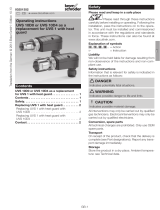
1 Application
1 Application
For monitoring gas burners of unlimited capacity with or
without fan, on hot-air furnaces, gas-fired boilers, industrial
furnaces and excess-gas flaring installations in conjunction
with Kromschröder automatic burner control units and
burner control units. The UV sensors monitor the gas burn-
ers in intermittent operation. The burners can either be ignit-
ed directly or operated as pilot and main burners.
UVS5
An old UVS5 (with non-detachable PVC cable) can be re-
placed with the new UVS5G1 (with cable gland and spring
force terminals).
UVS10
UV sensors UVS1, UVS6 and UVS8 can be replaced by
using various adapters with a heat guard made of quartz
glass.

UVS5, UVS10 · Edition 02.23 · EN 4
2 Certification
2 Certification
For certification, see Technical Information of the corre-
sponding automatic burner control unit or burner control
unit that the UV sensors UVS5 or UVS10 are to be used
with.
2.1 Eurasian Customs Union
The products UVS5, UVS10 meet the technical specifica-
tions of the Eurasian Customs Union.

UVS5, UVS10 · Edition 02.23 · EN 5
3 Function
3 Function
The UV tube detects the ultraviolet light of a flame. In the
case of incident UV light, alternating current flows through
the UV tube and is converted into a DC signal by the UV
sensor. The DC signal can be processed by a flame signal
amplifier.
The UV tube does not respond to daylight, incandescent
bulb light or infrared radiation emitted by hot workpieces or
red-hot furnace walls.
The designed lifetime of the UV tube is approximately
10,000 operating hours. For safety reasons, it must be re-
placed after this period.
UVS10
2
1
3
Signal (µA)
220/240 V~
UV
A quartz glass heat guard insulates the UV tube against the
hot furnace atmosphere and protects against moisture, dirt
and heat.
UVS5
2
1
3
Signal (µA)
220/240 V
~
UV
Protect the UV sensor against electrostatic charging by
grounding the combustion chamber or the bracket.

UVS5, UVS10 · Edition 02.23 · EN 6
3 Function
3.1 Part designations
UVS5
3
2
1
2
4
6
78
5
3
1 M20 cable gland
2 Housing
3 Spring force terminals (trm.1, trm.2, trm.3)
4 Sensor head
5 Positioning aid
6 Sticker
7 UV tube
8 Bracket
UVS10
1
2
4
3
6
5
78
1 Housing
2 Cable gland
3 UV tube
4 Adapter with quartz glass
5 Plug
6 Socket
7 Retaining screw
8 Seal

UVS5, UVS10 · Edition 02.23 · EN 7
3 Function
3.2 Electrical connection
Example: electrical connection to automatic burner control
unit IFD258
UVS 3
2
1
c
PE
ϑ
1 2 3 4 5 6 7 8 9 10 11 12
230V
L1 (L1)
N (L2)
s1
s2 v2v1
F1
13 14
IFD 258
max. 2 A,
253 V~
max.
2 A,
253 V~

UVS5, UVS10 · Edition 02.23 · EN 8
4 Replacement possibilities
4 Replacement possibilities
UVS1, UVS6 and UVS8 will be replaced by UVS10D,
UVS5 will be replaced by UVS5G1.
UV sensor Note
Old New
UVS1 UVS10D0G11)
Replaces UVS1 with heat guard. UVS1
connection cable can continue to be
used.
UVS5 UVS5G1
Old bracket, clamping collar and PVC
connection cable can continue to be
used.
UVS6 UVS10D0G1 UVS6 connection cable can continue to
be used.
UVS8 UVS10D2 UVS8 connection cable can continue to
be used.
1) With Rp 1/2 internal thread

UVS5, UVS10 · Edition 02.23 · EN 9
5 Selection
5 Selection
UV sensors UVS5, UVS10D0, UVS10D1, UVS10D4,
UVS10L0 and UVS10L1 can be equipped with an M20 ca-
ble gland for electrical connection.
5.1 ProFi
A web app selecting the correct product is available at
www.adlatus.org.
5.2 Type code
UVS UV sensor
5 Series 5
10 Series 10
D Quartz glass heat guard
L Quartz glass heat guard lens
0 Rp 1/2 internal thread
1 Rp 1/2 internal thread and cooling air connection
2 1/2 NPT internal thread
3 1/2 NPT internal thread and cooling air connection
4 UVS1 adapter (28mm (1.1"))
G1 M20 cable gland

UVS5, UVS10 · Edition 02.23 · EN 10
6 Project planning information
6 Project planning information
6.1 Installation
The UV sensor may only be exposed to the UV light of its
own flame. It should be protected from other sources of
ultraviolet light. These could be, for example: neighbouring
flames (this must be observed when monitoring pilot and
main burners in particular), ignition sparks, arcs from weld-
ing devices or lamps emitting ultraviolet light.
Do not expose the UV sensor viewing opening to direct
sunlight to avoid incorrect flame signals.
Direct the UV sensor at the flame inclined from above or in
the horizontal so that no dirt collects in front of the UV sen-
sor.
UVS5
< 400mm
(16")
The sensor is mounted using the bracket supplied which is
attached to the burner.
The UV tube can be directed towards the flame from the
side or front with the help of the viewing openings in the
sensor head.
UVS10
< 400mm
(16")
Purge air/
Cooling air
The sensor is mounted to a ½" viewing tube using the
adapter (supplied) with integrated quartz glass heat guard.
The viewing tube should be directed at the first flame third,
as this is where the highest UV radiation is generally found.
The inside of the steel tube should not be coated.
Supply cooling air to cool and protect the optical system
from soiling and condensation.
6.2 Weak UV radiation
UVS10
In order to concentrate weak UV radiation more effectively
and to achieve a stronger UV signal, a quartz glass lens is
available for the UVS10, see page 13 (7.5 Quartz glass
disc for UVS10). When installing, ensure that the lens cur-
vature points towards the flame. Thereby, the UV sensor
must be precisely directed at the flame.

UVS5, UVS10 · Edition 02.23 · EN 11
6 Project planning information
6.3 Purge air/Cooling air
UVS10
The UVS10 can be supplied with cooling or purge air
through a cooling air adapter for cooling purposes and to
protect the lens from soiling and condensation. Various
nozzles for the cooling air adapter can be supplied for ad-
justing the air volume and the O2 content perfectly to the
site conditions, see page 12 (7.4 Cooling air adapter for
UVS10).
0
0,2
0,4
0,6
0,8
1,0
1,2
1,4
1,6
1,8
2,6
2,4
20
0
10
30
40
50
60
70
80
90
100
2,2
3,0
2,0
2,8
Cold air purge
Cooling air for hot air operating mode
Ø 2.3 mm nozzle
Air flow rate [m3/h]
Δp air [Pa]
Δp air = air pressure upstream of nozzle - burner reverse flow pressure
(burner reverse flow pressure on BIC/BIO/ZIC/ZIO = air pressure on burner)
= recommended purge air volume range
Ø 3.3 mm nozzle
Ø 4.5 mm nozzle
A purge air nozzle is not required for Kromschröder burners
(BIO, BIC, ZIO, ZIC) if they are used with cold combustion
air.
A nozzle with a diameter of 4.5mm can be used for pro-
cesses which are not O2 critical.
6.4 Electrical connection
The UV sensor is operated with an alternating voltage of
220/240V. The voltage is provided by the automatic burner
control unit or the flame detector.
Wire the UV sensor according to the connection diagram of
the relevant automatic burner control unit or flame detector.
A grounded mains is not required.

UVS5, UVS10 · Edition 02.23 · EN 12
7 Accessories
7 Accessories
7.1 UV tube for UVS5
With sticker and seal
Order No.: 7 496 068 7
7.2 UV tube for UVS10
Order No.: 7 496 044 5
7.3 Adapter UVS1 for UVS10
50 mm
(1.96")
ø28 mm (1.1")
ø36 mm (1.4
")
With quartz glass heat guard
Order No.: 7 496 061 5
7.4 Cooling air adapter for UVS10
60 mm
(2.36")
25 mm (0.98")
Rp ¼
With quartz glass heat guard
Rp 1/2, Order No.: 7 496 061 4
1/2 NPT, Order No.: 7 496 061 3
Nozzle for cooling air adapter, Order No.: 7 496 061 6

UVS5, UVS10 · Edition 02.23 · EN 13
7 Accessories
7.5 Quartz glass disc for UVS10
To protect the UV tube
Quartz glass disc with seal,
Order No.: 7 496 061 2
Quartz glass lens with seal
When installing, ensure that the lens curvature points to-
wards the flame. Precisely align the UV sensor. The gap
between the UV sensor and the flame can be increased to
approximately 600 to 1200mm (23" to 47").
Order No.: 7 496 061 1

UVS5, UVS10 · Edition 02.23 · EN 14
8 Technical data
8 Technical data
8.1 UVS5
Ambient conditions
Condensation and dew in and on the unit are not permitted.
Avoid direct sunlight or radiation from red-hot surfaces on
the unit.
Avoid corrosive influences, e.g. salty ambient air or SO2.
Ambient temperature:
-40 to +80°C (-40 to +176°F).
Storage temperature:
-40 to +80°C (-40 to +176°F).
Transport temperature = ambient temperature.
Enclosure: IP 54 (Nema 3),
IP 40 around the viewing openings with fitted tube and seal.
Permitted operating altitude: ‹ 2000m AMSL.
Mechanical data
Plastic housing with connection terminals.
Designed lifetime of the UV tube:
approx. 10,000 operating hours.
Distance between UV sensor and flame:
max. 400mm (max. 16").
Weight: 70 g (0.15lbs).
Max. length of cable between UV sensor and automatic
burner control unit:
see instructions for automatic burner control unit.
Electrical data
Cable gland for cable diameters:
7 to 13mm.
UV tube: P578,
spectral range: 190–270nm,
max. sensitivity: 210 nm ± 10 nm.
Min. DC signal: 1 μA.
Dimensions
15 mm
(0,59")
22 mm
(0.87")
50
(1.97")
65
(2.55")
117
(4.6")
150 mm
(5.9")
33,8 mm
(1.5")
5 mm
(0.2")
36 mm
(1.42")
SW24

UVS5, UVS10 · Edition 02.23 · EN 15
8 Technical data
8.2 UVS10
Ambient conditions
Condensation and dew in and on the unit are not permitted.
Avoid direct sunlight or radiation from red-hot surfaces on
the unit.
Avoid corrosive influences, e.g. salty ambient air or SO2.
Ambient temperature:
-40 to +80°C (-40 to +176°F).
Storage temperature:
-40 to +80°C (-40 to +176°F).
Transport temperature = ambient temperature.
Enclosure: IP 65.
Permitted operating altitude: ‹ 2000m AMSL.
Mechanical data
Aluminium housing with integrated heat guard, with con-
nection terminals.
Designed lifetime of the UV tube:
approx. 10,000 operating hours.
Distance between UV sensor and flame:
300–400mm (12 to 16"),
with quartz glass lens:
approx. 600 to 1200mm (23 to 47").
Weight: 280 g (0.6lbs).
Max. length of cable between UV sensor and automatic
burner control unit:
see instructions for automatic burner control unit.
Electrical data
UV tube: P578,
spectral range: 190–270nm,
max. sensitivity: 210 nm ± 10 nm.
Min. DC signal: 1 μA.
Dimensions
80 mm
(3.15")
47 mm
(1.85")
45 mm
(1.77")
ø26 mm (1.02")
½"
42 mm (1.65")
SW 24


UVS5, UVS10 · Edition 02.23 · EN
The Honeywell Thermal Solutions family of products includes Honeywell
Combustion Safety, Eclipse, Exothermics, Hauck, Kromschröder and
Maxon. To learn more about our products, visit ThermalSolutions.honey-
well.com or contact your Honeywell Sales Engineer.
Elster GmbH
Strotheweg 1, D-49504 Lotte
T +49 541 1214-0
hts.lotte@honeywell.com
www.kromschroeder.com
For more information
© 2023 Elster GmbH
We reserve the right to make tech-
nical modifications in the interests of
progress.
/