Page is loading ...

Portable HF SDR Transceiver
Operation manual
G90
Ultra-Miniature 24 Bit SDR
V1.01.00
April 2019

2
Basic Features 3
Panel Buttons 4
Front Panel 4-7
Rear Panel 8
Side Panels 8
Connector Pin-Outs 9
MIC Buttons 10
External Power Connection 11-12
LCD Display 13
Power On/Off 14
Bands Selection 15
Operating MODE Selection 16
Volume Adjustment 17
Multi-function Adjustment Knob 18
Adjusting Transmit Power 19
Setting Operation Frequency 20
Automatic Antenna Tuner 21
Function Buttons 22-23
VFO and Split (SPL) Operation 24
CW Transmission 25
SWR Scanner 26
Digital Bandwidth Filter 27
Line Input /Output Selection 28
Channel Memories 29
Setting Boot Screen Callsign 30
System Menu 31
PC Data Comm. Connections 32
System Parameter Settings 32
Computer Control Instructions 33
Band/Voltage Output for Ext. Amp 33
Specifications 34
Packing Items List 35
G90 and XPA125B Connection Diagram 36
CE-19 Expansion Card Interface 37
Copyright Statement 38

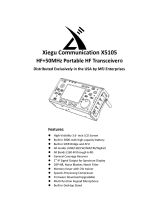
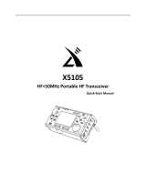
Basic Features
3
The G90 is a portable 20W HF SDR amateur radio transceiver with built-in auto antenna tuner. The display unit and
the radio can be separated. It is a new member of the Xiegu product family and the first model of the new “G” series.
The G90 is a 24-bit 48kHz sampling rate SDR. It has excellent TX/RX performance and a highly configurable user
interface.
High performance front end with narrowband pre-selection filters
Covers the frequency range of 0.5~30MHz, SSB/CW/AM/ FM*
1.8 inch - high brightness color TFT LCD screen
±24k bandwidth spectrum and waterfall display
Software defined RX bandpass filters (CW mode down to 50Hz)
Detachable Front display unit
Up to 20W RF power output
Built-in wide range automatic antenna tuner
Extensive Input / Output connections
Baseband I/Q output. Interface with any external device that can handle baseband I/Q, including sound card-
based or PC-based applications.
Please read this manual fully before operation so as to get a good understanding of the G90’s capabilities and functions.
*1: The FM mode can only be turned on when the GSOC controller is used together.

Side Panel
4
1 Volume knob
Turn to control the speaker volume.
Short Press In: Switches to headphone output mode.
2 Power/ Receive or transmitting status pilot lamp.
Standby/receive status: Yellow-green
Transmitting status: Red
3 Power switch
Press In to boot up & start radio
With Radio On: Press In and hold to shut down
4 Multi-function adjustment Knob
Default state: Turning this knob will step at 100 kHz.
Press and hold this knob to select Custom Functions.
5~6 Mode switching
TX/RX Mode switching
7~8 BAND Switching – Change Bands
9 FUNC Indicator light
When the function button is pressed, this LED will light
yellow to indicate you are using the alternate functions of the
other control buttons.

Side Panel
5
10 F Indicator light
This LED will light yellow when you have CW tuned
into the correct pitch. It will blink in sync with the
incoming CW characters.
11 Main Knob
Operating this knob will change the current frequency.
(VFO)
Function buttons:
12. TUNE: Antenna Tuner on/off and set.
13. Po: Transmitter power output adjust
14. KEY: CW speed, QSK, key type and ratio
15. LOCK: Lock button controls

Side Panel
6
G90 Front Panel Connector Layout:

Side Panel
7
16. Headphone interface(On the left side of the control head)
This 3.5mm stereo jack (3-pin) for connecting standard headphones.
17. Communication interface (On the left side of the control head)
This 3.5mm jack is currently used for updating the control head’s internal firmware. The programming cable is
included with the radio’s accessories. The Firmware update files and TerraTerm program used to update the G90 are
available on the Xiegu website. It may also be used for CAT control of the G90. Other uses for this port may be
implemented in future firmware updates.
18. MIC Interface(On the right side of the control head)
Connecting the multi-function MIC to this connector.

Rear Panel
8
19. Antenna interface
SQ-239 type. Impedance 50Ω
20. KEY interface
The interface is a 3.5mm stereo jack for connection
to manual/automatic CW keys.
CW key connection diagram:
For manual CW keys:
Connect Dit and Dash
together.
21. COMM interface
Firmware Expandable I/O connection.
Currently used for main unit Firmware updates.
22. I/Q Signal output
The interface is a 3.5mm stereo jack for “I/Q” signal
output.
23. ACC
The interface is an 8-pin mini DIN interface. Pinout is
shown in the connector description.
24. DC Power Cable Connector
25. Ground Terminal Connection

Rear Panel
9
1、 MIC Interface
2、 COMM Connector
3、 Headphone Interface
4、ACC Interface
5、CW Key Wiring Diagram
PTTBAND
AF_IN
AF_OUT
ALC
DATA
+8V
GND
MIC
MDATA
GND
MIC
MICE PTT
MSVSW
NC
+8V
TXD
RXD GND

MIC Buttons
10
1、LOCK
2、PTT
3、UP / DOWN
4、RX/TX indicator
5、Numeric keypad
6、FIL
7、MODE
8、Function indicator
9、Function button
10、MW
11、V/M
12、XFC
13、TUNER
Lock button
Transmit control button
Frequency "+" or "-" buttons
Hand Mic operation indicator
Numeric keypad area
Filter selection
RX/TX operation mode
LED
F1/F2-configurable settings
Memory Storage operation
Frequency/channel switching
Actual TX Freq Select (Split)
Hold press to turn on the built-in
automatic antenna tuner for tuning.

External Power Connection
11
The G90 can use a 13.8V external DC power supply. The DC power supply must have a current load capacity of at
least 10A. 13.8-14.3 VDC required for 20 watts output. The supplied power cord can be used to connect radio and your
DC power.
When connecting the DC power supply - please be very careful to observe the connections to avoid reverse polarity!
The red wire is connected to the positive pole of the power supply, and the black wire is connected to the negative
pole of the power supply.
When you use an external power supply, in order to prevent external interference from entering the radio through the
power line or the radio radiating RF out of the power line, use a clamp-on or loop-through Ferrite choke. Place it as close
to the radio’s power connector as possible.

External Power Connection
12
When using an external power supply, carefully check the polarity of the power cord and do not
reverse the polarity.
The limited warranty of this radio does not include damage caused by an external power
connection error or damage caused by improper power supply voltage.
As close as possible to the plug.
The power cord wraps around
the ferrite core 2 turns.

LCD Display
13
Many of the G90’s buttons have dual functions. Main functions are accessed by a short press and alternate functions
are accessed by a long-press of the control button. All the functions states and values are reported through the 1.8”
color LCD screen.
Interface display as follows:
Main frequency Display
Power Supply
voltage
Volume
Functions Display Area
Standing Wave Ratio
Signal Level in dBm
Waterfall Display
Status Display
Mode
VFO status
S-Meter and Power Meter
Spectrum Display

LCD Display
14
Turn on/off Transceiver
1、Turn on:press PWR button.
2、Turn off:Power on state,Hold press button 1 second.
To turn OFF LCD screen (save batt power):
When the G90 is ON, quickly tap the main PWR
button and the LCD screen will power off.
The radio will remain ON. Hit any button on the
radio to turn the LCD screen back ON. Tap the
LOCK button and the LCD will step through
different brightness levels.
Power button

LCD Display
15
Operating frequency band selection
To Change Operating Band:
Press the BAND < or > button. This will increment or decrement through the Ham bands.
Each amateur band has a user-defined frequency range associated with it.
The radio will be configured to allow 60 meter band operation if your country permits it.
The G90's frequency range covers 0.5 to 30 MHz.
Amateur frequencies within this range are divided
into 10 bands. Band switching can be performed in a
number of different ways. SW bands are included.
-
+
3.5MHz 7.0MHz 10MHz 14MHz
18MHz
21MHz
24MHz
1.8MHz
28MHz
5.2MHz

LCD Display
16
VFO-A and VFO-B are two independent VFO’s that can be set independently.
Operating mode select
The FM mode can only be turned on when used with the GSOC controller.
Pressing the [ MODE ] button increments through the available
operating modes.
:
Mode left loop
Mode right loop

LCD Display
17
VOLUME CONTROL
Speaker mode:
Headphone mode:
VOX mode on / off:
Press and hold the [FUNC] button for over 1 second.
Press the volume knob briefly to enter the VOX function settings.
VOX menu description:
VOX OFF/ON: VOX function off/on
VOX GAIN: Voice Control Gain Setting
ANTI-VOX: Hand mic speaker noise-trip suppression setting
VOX DLY: VOX hold delay setting
The voice control function can be enabled for both the hand microphone and the line input LINE.
Rotate the volume knob left or right to adjust
the level of received volume.
Press the volume knob inwards momentarily
to enter headphone mode and mute the
speaker.
Rotate the volume knob left or right to
adjust the level of the headphone volume.

LCD Display
18
This is handy for use when you only connect the RX and TX audio lines to the Acc.
This will Key the G90’s TX key the radio automatically using digital modes. (no CAT required)
When using the AF IN port of the ACC interface for line input audio, set the appropriate input volume level in the system menu.
This will have an effect on the VOX level setting- so set it first.
Multi-function adjustment knob
The multi-function knob controls many of the radios functions and settings
Operation method:
Default: VFO tuning in 100 kHz frequency increments.
Short press: Enter SQL item to adjust SQL level.
Hold press:Goes to the User Custom feature menu.
Rotate the main knob to select the appropriate item.
Short press the “SAVE” key to select that menu item.
At this point, the featured item is adjusted by the multi-function adjustment knob.
The Save and Exit buttons are the first two under the LCD. Save = PRE Exit = COMP
Multi-function adjustment knob

LCD Display
19
The customizable features are as follows:
1) Frequency steps
2) SQL Level
3) Po Level, transmit power setting
4) Key Speed, automatic key rate setting
5) FFT Scale - spectrum reference level setting
Adjustment transmitting Power Output (Po)
*When using the G90 transceiver for the first time without knowing for sure your antenna has a low SWR, minimize the set
transmit power output.
Operation method:
1、 Short press the [Po] button to set.
2、 Then use the multi-function knob to
set the output power in 1W
increments.
PO
Multi-function
Adjustment
Knob

LCD Display
20
Set the operating frequency
2. Rotate the Multi-function knob – 100khz increments
3. Set the frequency manually using the microphone:
Press the [F-INP ENT] button on the microphone. The G90 enters the frequency setting state. The cursor will blink in the
first position on the left side of the frequency display.
Enter the frequency values you want to set, and then press the [F-INP ENT] button again to complete the frequency setting.
For example, set the current frequency to 14.09000MHz, and the key order is as follows:
1. First press the [F-INP ENT] button;
2. Press the 1 4 . 0 9 0 0 0 number key in sequence;
3. Press the [F-INP ENT] button again, complete the setup.
There are three ways to set the G90 operating frequency. You can use
the large main tuning knob, the multi-function knob and the
microphone.
1. Set the tuning steps using the main knob
Short press the main knob, select 100Hz, 1kHz, 10kHz steps.
Rotate the main knob to set the frequency of the current
step.
Main Knob
/