Page is loading ...

StarLink™ SLE Commercial Series Alarm Communicators -- Installation Instructions 1
Control Center reports a trouble signal in the event that the
network does not receive the expected supervision signal
from the wireless communicator. In addition, all models
are powered directly from the control panel.
For Commercial Burglary installations, under the
armed condition, any loss of communication must be
treated as a Burglary Alarm at the Central Station.
The model names are as follows:
SLE-GSM-3/4G - Commercial / Residential Burglary and
Residential Fire 2G, 3G and 4G Network Compatible
GSM alarm capture Communicator, SIM card included.
Black plastic enclosure.
SLE-GSM-8D-3/4G - Commercial / Residential Burglary
and Residential Fire 2G, 3G and 4G Network Compati-
ble GSM alarm capture Communicator. Supports re-
mote downloading to the Gemini GEM-P400, GEM-
P800, GEMP-801, Express XP-400 and XP-600 series
control panels. SIM card included. Black plastic enclo-
sure.
SLE-CDMA - Commercial / Residential Burglary and Resi-
dential Fire Universal CDMA alarm capture Communica-
tor. Black plastic enclosure.
SLE-CDMA-8D - Commercial / Residential Burglary and
Residential Fire Universal CDMA alarm capture Com-
municator. Supports remote downloading to the Gemini
GEM-P400, GEM-P800, GEMP-801, Express XP-400
and XP-600 series control panels. Black plastic enclo-
sure.
SLE-GSM-FIRE - Commercial / Residential Fire and Bur-
glary 2G, 3G and 4G Network Compatible GSM alarm
capture Communicator. SIM card included. Red plastic
enclosure.
SLE-CDMA-FIRE - Commercial / Residential Fire and Bur-
glary CDMA radio in red plastic enclosure.
ADDITIONAL COMPONENTS
In addition to the models listed above, the following sub-
assemblies are available:
SLE-DLCBL - Download Cable, 6 feet.
SLE-ANTEXT - Extended antenna with 15 feet of cable.
WI2120.a 04/15
333 Bayview Avenue
Amityville, New York 11701
For Sales and Repairs, (800) 645-9445
For Technical Service, (800) 645-9440 or visit us at
http://tech.napcosecurity.com/
(Note: Technical Service is for security professionals only)
Publicly traded on NASDAQ Symbol: NSSC
© NAPCO 2015
INTRODUCTION
The StarLink™ Commercial / Residential Fire and Burglary
alarm capture radio communicators are fully supervised,
wireless digital two-way subscriber units supported by an
extensive nationwide wireless network. All models are
compatible with most 12VDC alarm control panels (always
adhere to the documentation provided by the control panel
manufacturer). All can function as a backup to existing tel-
ephone lines, or as a primary communicator. In backup
mode, all units will automatically switch the communication
channel from the telephone line to the network when tele-
phone line trouble is detected. For Commercial installa-
tions, mount the unit to a single-, dual-, or three-gang elec-
trical box and route the wires through the back knockout(s),
or as specified by local codes. See WI2140 for program-
ming information.
The SLE Series radios use proprietary data-capture tech-
nology that captures the alarm report from the control panel
and transmits the alarm signals to the SLE Control Center;
the alarm signals are then forwarded to ANY central station
via Contact ID or Sur-Gard System II via TCP/IP. The SLE
STARLINK RADIO REPORTING PATH
The diagram below shows the transmission path of a
signal from the StarLink radio to the central station.
1. Signal from a Control Panel.
2. StarLink radio receives the signal transmission
(from the TIP an RING wires); sends RF signal
through the GPRS network operator.
3. Network Operator, part of the vendor system, a
section of the cellular spectrum.
4. SLE Control Center, receives and routes data.
5. Central Station.
( ( ( ( ( ( ( ( ( ( ) ) ) ) ) ) ) ) ) )
(1)
(2)
Control
Panel
Network
Operator
StarLink Network
Operations Center
(3)
CENTRAL
STATION (5) (4)
StarLink
Radio
StarLink™ SLE
Residential / Commercial Series
Alarm Communicators
INSTALLATION INSTRUCTIONS
AGENCY LISTINGS
UL 864 Standard For Control Units and Accessories For Fire
Alarm Systems, 9th Edition
UL 1610 Standard For Central-Station Burglar-Alarm Units
UL 985 Standard For Household Fire Warning System Units
UL 1023 Standard For Household Burglar-Alarm System
Units
CDMA models are Verizon® Network Certified

2 StarLink™ SLE Commercial Series Alarm Communicators -- Installation Instructions
SPECIFICATIONS
The following specifications apply to all StarLink radio mod-
els unless otherwise stated:
Electrical Ratings for +12V (all models powered by the
control panel)
Input Voltage: 11-15VDC (power-limited output from Listed
control panel)
Input Current: 65mA with peak RF transmission current of
400mA for models SLe-GSM, SLe-GSM-3/4G, SLE-CDMA
and the SLE-CDMA-FIRE; (80mA with peak RF transmis-
sion current of 400mA for models SLe-GSM-8D-3/4G and
the SLE-CDMA-8D)
Electrical Ratings for the IN 1 Burg/Fire Input:
Input Voltage: 9-15VDC
Maximum Input Current: Up to 2mA from FACP NAC circuit
Electrical Ratings for IN 2 and IN 3:
Maximum Loop Voltage: 15VDC
Maximum Loop Current: 1.2mA
End of Line Resistor (EOLR) Value: 10K (2 req'd)
Electrical Ratings for 3 PGM Outputs:
Open Collector Outputs: Maximum Voltage 3V when ac-
tive; 15V maximum when not active
Maximum PGM Sink Current: 50mA
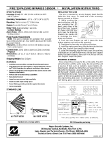
Physical (W x H x D)
Plastic Housing: 8 x 5-29/64 x 1½" (20.3 x 13.9 x 3.8cm)
Mounting: Plastic housing includes three keyhole slots for
triple gang boxes (see scale template on page 19);
Environmental
Operating Temperature: 0°C - 49°C (32°F - 120°F)
Humidity: Maximum 93% Non-Condensing
Indoor use only
TERMINAL DESCRIPTIONS
Configure all inputs and outputs using the Management
Center screen (located at www.napconoc.com). Located at
the bottom of the StarLink radio PC board, the 17 terminals
are described as follows:
TB1: PWR (+12V)
(Refer to section "STEP 4: APPLY POWER")
TB2: PWR GND (–)
(Refer to section "STEP 4: APPLY POWER")
TB3: PGM1 (–): Open collector output. PGM1 is nor-
mally on (active low). When it is triggered (for ex-
ample, a trouble is detected) it becomes open col-
lector/high. To have a zone dedicated to an Star-
Link radio trouble, insert one side of the end of line
resistor into this PGM1 terminal, and wire the other
side of the resistor to the positive terminal of the
zone.
TB4: PGM2 (–): Open collector output. This output is
defaulted as "Fail to Communicate", and is normally
open collector/high. When a report fails to com-
municate anywhere in the communications path, the
output is active low.
TB5: PGM3 (–): Open collector output. This output is
defaulted as "Telephone Line Cut". When the tele-
phone line voltage is correct, the output is open col-
lector/high; when the telephone line voltage is too
low, the output is active low.
TB6: IN 1: Active high input for wiring to the control
panel bell output. When this input detects a pulsing
temporal 3 high, it sends a Fire alarm; a pulsing
temporal 4 (CO Alarm), a CO alarm is sent. When
used, these conductors must be run in conduit (max
20 feet for Commercial Fire, and 3 feet for Residen-
tial Fire). Do not use for Burglary applications. For
this input to report to a central station, the StarLink
radio must be configured with the central station
telephone number and correct reporting formats and
codes.
TB7: IN 2: See TB9, below.
TB8: GND: Common ground terminal.
TB9: IN 3: Both terminals IN 2 and IN 3 by default are
supervised end-of-line resistor inputs that can be
triggered with N/O or N/C relay contacts. Wire the
common ground terminal GND (terminal TB8) to the
NOTICE TO AUTHORITIES HAVING JURISDICTION, USERS, INSTALLERS,
DEALERS, AND OTHER AFFECTED PARTIES
FIRE PROGRAMMING OPTION PERMITTED IN
UL864? (Y/N) AVAILABLE SETTINGS REQUIRED UL 864 SETTINGS
Unattended Remote Downloading No Enable / Disable
Disabled (Jumper 1 installed). Also required for Commercial / Burgla-
ry installations. Note: See page 7 "Configuration Download / Firm-
ware Updates" for jumper instructions.
IN2 and IN3 Unsupervised No Supervised / Unsupervised Supervised (Jumpers 4 and 5 installed)
7 Day Supervision, Radio to NOC No 200 seconds, 5 minutes,
60 minutes, 7 days 200 seconds, 5 minutes
4/2 Reporting No 4/2 or Contact ID Contact ID

StarLink™ SLE Commercial Series Alarm Communicators -- Installation Instructions 3
relay common. When used as arm/disarm status
input, a low indicates "armed" and a high indicates
"disarmed". For these inputs to report to a central
station, the radio must be configured with the cen-
tral station telephone number and correct reporting
formats and codes. See table on page 20 for more
information.
TB10: TIP: See TB11, below.
TB11: RING: Terminals TIP and RING: When used for
backup reporting, the house tip and ring telephone
wires must be routed from the outside to these ter-
minals. Under normal back up conditions, these
terminals are internally wired to the PANEL TIP and
PANEL RING terminals, allowing all transmissions
to the central station to be monitored. These wires
are monitored for voltage such that if voltage falls
below 1.5V, a Telco Line Fault trouble is detected,
and the StarLink radio applies telephone line volt-
age to the control panel Tip and Ring allowing it to
receive and transmit any alarms sent by the control
panel.
TB12: PANEL RING: See wiring diagrams.
TB13: PANEL TIP: See wiring diagrams.
Note: TB14-TB17 no connections permitted by UL.
TB14: RTS (R): See TB17 below.
TB15: PANEL TX (B): See TB17 below.
TB16: PANEL RX (G): See TB17 below.
TB17: CTS (Y): No connections permitted.
LED DESCRIPTIONS
The PC board contains several LED's, as follows:
GREEN RF SIGNAL STRENGTH LED
Labeled "D3", this LED is located at the lower right cor-
ner of the PC board.
Every 30 seconds, the StarLink radio receiver section
turns on and listens to the cell tower. Depending on the
signal strength detected, it will blink the Signal Strength
LED from 1 to 8 times, providing a signal strength indica-
tor that is updated constantly and is always displayed.
Refer to Coverage Table below.
Green LED Operation
Signal strength (as received by the radio) is displayed by
this LED blinking 1 to 8 times at a constant rate (with a
short delay between blink cycles). Acceptable power
level is greater than or equal to -91dBm (minimum 4
blinks at the mounting location).
YELLOW OPERATIONAL STATUS LED
Labeled "D4", this LED is located at the bottom right of
the PC board. Operation is as follows:
GREEN RF SIGNAL STRENGTH LED
RADIO RECEIVER COVERAGE TABLE
LED Blinks 8 7 6 5 4 3 2 1
-55 -65 -75 -85 -91 -95 -99 -105
Power
(dBm)
LED LOCATIONS
D4 D3 D5
RED DIAGNOSTIC LED (Labeled "D7")
YELLOW OPERATIONAL STATUS LED (Labeled "D4")
GREEN RF SIGNAL STRENGTH LED (Labeled "D3")
RED TROUBLE LED (Labeled "D5")
Supervised Fire / Burg Input
10K
10K
C C N/C
Alarm
N/C
TBL
To StarLink
Terminals
IN2 (TB7)
-or-
IN3 (TB9)
Radio GND
(TB8)
The EOLR must be installed and located within the control panel housing.
(Radio)
(Alarm Panel)
8 7 9
-or-
Supervised Arm / Disarm Input
10K
10K
C
Open = Disarmed
Closed = Armed
The EOLR must be installed and located within the control panel housing.
Radio GND
(TB8)
(Radio)
(Alarm Panel)
8 7 9
-or-
To StarLink
Terminals
IN2 (TB7)
-or-
IN3 (TB9)

4 StarLink™ SLE Commercial Series Alarm Communicators -- Installation Instructions
PRIMARY AND BACK-UP REPORTING
The StarLink radio can function as a primary wireless
communicator, in cases where there are no telephone
lines present, when connected directly to the control pan-
el Telco terminals. For primary reporting, do NOT install
jumper 3 in terminal block "X5". The StarLink radio can
also function as a backup to the existing telephone lines
(install jumper 3 in terminal block "X5"). When used as a
backup communicator and when it senses telephone line
trouble, the StarLink radio automatically switches the
communication channel from the telephone line to the
GPRS network. See the following table for the maximum
number of retry attempts from the SLE radio to the NOC:
NETWORK COVERAGE
The StarLink radio constantly supervises the GPRS net-
work coverage. When the StarLink radio is configured
for primary reporting, and the StarLink radio detects a
loss in network coverage, the StarLink radio must be
configured to prompt the control panel to announce a
Telco Line Cut failure trouble using the Management
Center screen (located at www.napconoc.com). Note:
This Telco Line Cut failure trouble will NOT activate when
the StarLink radio is configured for backup reporting.
INSTALLATION STEPS
STEP 1: ACCOUNT REGISTRATION
Create a new account and register specific StarLink radio
modules at www.NapcoComNet.com. Accounts and
modules registered via the Internet are enabled for activa-
tion within 24 hours.
STEP 2: SELECT A MOUNTING LOCATION
The mounting location should be indoors within the pro-
tected area and selected based on RF performance. It is
HIGHLY recommended that the installer carefully adhere
to the following recommendations BEFORE any wires are
installed.
Generally, high locations are best. DO NOT mount
radio in basements or below grade as unpredictable
performance may result.
DO NOT mount the radio in non-climate controlled en-
vironments (i.e. attics may become extremely hot in
summer, garages may become extremely cold in win-
ter).
Avoid mounting locations within 3 feet of AC power
lines, fluorescent light fixtures, or large metal objects
(air conditioners, metal garage doors, etc.) as these
Normal Standby Condition:
Blinks on momentarily every 10 seconds: Unit is
in standby waiting for an alarm to report.
Processing Alarm Conditions:
When processing an alarm, this LED will blink variably
during each part of the process (dialing, handshaking,
data transmission, etc.).
RED TROUBLE LED
Labeled "D5", this LED is located at the bottom right of
the PC board. Operation is as follows:
1 Blink: Low Aux Power input voltage
2 Blinks: Battery trouble
3 Blinks: Alarm report Failed to Communicate
4 Blinks: RF trouble (antenna connection or cellu-
lar registration)
5 Blinks: Network trouble (signal unable to reach
the SLE Control Center)
6 Blinks: Unit disabled (reporting or control panel
downloading not allowed)
7 Blinks: Unit was shutdown and has no function-
ality; requires a restart (full power down and full power
up sequence) to restore operation
8 Blinks: Telco Line Cut
RED DIAGNOSTIC LED
Labeled "D7", this LED is located in the middle of the
PC board. One blink indicates a weak or non-existent
signal from the network (green LED is off). If this red
LED is blinking in any other manner, please contact
technical support.
SUPPLYING POWER
Control panels can provide power through their Auxiliary
Power terminals if the available standby current is reduced
by 65mA. When there is insufficient standby current due to
the application (such as when 24-hour standby time is re-
quired for Fire or CO), the SLE-ULPS-R Charger Module
accessory must be used to charge an additional battery
and to supply the standby current for the StarLink radio.
See WI2131.
JUMPER DESCRIPTIONS
Jumper block labeled "X5"; from top to bottom, as detailed
in the following table. Note: Contact ID is always availa-
ble in response to a Contact ID handshake.
NOC
Telephone #
Max # of
Retry
Attempts
to the NOC
Comments
Primary 3 Primary central station tele-
phone number used
Backup 6 Backup central station tele-
phone number used
Jumper Block "X5" Options
Jumper block labeled "X5" contains 5 jumper terminals; from top (labeled
"1") to bottom (labeled "5") as follows:
Jumper ON Jumper
Number Jumper OFF
Tech on site must temporarily
remove to download 1 Not permitted by UL 864 and
UL 1610
4/2 with Checksum Pulse Format* 2 4/2 Pulse Format*
Backup Mode 3 Primary Mode
One or two 10K EOLR(s) Required 4 and 5 Not permitted by UL 864 and
UL 1610
*See table "NOTICE TO AUTHORITIES HAVING JURISDICTION..." on page 2.

StarLink™ SLE Commercial Series Alarm Communicators -- Installation Instructions 5
locations have been shown to have a detrimental effect
on signal strength.
A fair amount of care may be required to mount the ra-
dio so as to achieve an optimal RF path. The installer
should spend as much time as needed to obtain the
highest signal level possible.
For Commercial Burglary installations, install in accord-
ance with UL 681, Standard for Installation and Classifi-
cation of Burglary and Holdup Alarm Systems. Installa-
tion shall also be in accordance with UL 827, Standard
for Central-Station Alarm Services, and UL 1641, Stand-
ard for Installation and Classification of Residential Bur-
glar Alarm Systems.
a. Before applying power, be sure to connect the
antenna. Temporarily connect power to the radio
from a fully charged 12V (4AH minimum) battery.
DO NOT mount the StarLink radio at this time.
b. Position the unit in the desired mounting location,
with antenna oriented vertically. The signal strength
is displayed by the Green "Signal Strength LED" la-
beled "D3" (located at the lower right corner of the
PC board). The GSM radio tower signal strength
may fluctuate from day to day, therefore it is best to
try to find a mounting location where the LED pro-
vides a minimum of 4 blinks.
c. Once a location has been selected based on signal
coverage, permanently secure the unit using #8
screws (not supplied) in the two mounting holes.
WARNING: To ensure user safety and to satisfy FCC
RF exposure requirements, this unit must be installed so
that a minimum separation distance of 60cm (24") is al-
ways maintained between the antenna of the transmitting
device and nearby persons. Use ONLY the existing an-
tenna supplied by radio to comply with this warning
(Exception: The SLE-ANTEXT extended antenna with
15 feet of cable).
STEP 3: WIRING (PRIMARY AND BACKUP MODES)
22-gauge wire may be used if mounted up to 50 feet from
the control panel, and 18-gauge wire should be used for up
to 100 feet. Reference the wiring diagrams further in this
manual. See the section CONTROL PANEL PROGRAM-
MING further in this manual.
NOC Originated
Alarms
Contact ID
Event Data
Sent
Pulse Format
Event Code
Sent
Initiated By Comments
Supervisory Fail E356 A00 Zn000 99 Automatically by NOC if fail to receive
any signal from StarLink radio within
Supervisory Timeout duration.
For Auto Enroll, uses captured telephone
number, Sub ID and format. For Dealer
Programmed, uses entered telephone
number, Sub ID and format.
Press to Send
Test Signal E601 A00 Zn000 98
Manually by dealer from the Manage-
ment Center Signal Log screen
(located at www.napconoc.com).
Sends test into CS receiver.
Same comment as above.
Press to Send
Radio Test
Not Applicable
Nothing sent to
CS receiver Not Applicable
Manually by dealer from the Manage-
ment Center Checkins screen (located
at www.napconoc.com). Sends a com-
mand to the StarLink radio to force a
check-in to the NOC.
----
SIGNALS ORIGINATED AT THE NOC
STARLINK RADIO RELATED EVENT
REPORT CODES (Contact ID by default)
EVENT AREA CONTACT ID
CODE ZONE #
IN 1 Fire 0 E110 990 1A
IN 2 Panic 0 E120 992 22
IN 3 Trouble 0 E300 993 F3
Low Battery/Voltage 0 E302 994 F4
Tamper Trouble 0 E341 995 F5
Line Cut 0 E352 996 F6
Reboot 0 E625 997 F7
IN 1 CO (Carbon Monoxide) 0 E162 998 18
Panic Alarm* E123
Holdup Alarm* E122
Medical Alarm* E100
24 hour Aux. Alarm* E150
24 hour Aux. Restore* R150
Burg Perimeter Alarm* E131
Burg Interior Alarm* E132
Keypad Holdup Alarm (ambush)* E121
Keypad Panic Alarm* E123
Keypad Emergency Alarm* E140
Opening* E401
Closing* R401
A.C. Trouble* E301
Tel 1 Fail* E351
*Not generated by the StarLink radio.
**See table "NOTICE TO AUTHORITIES HAVING JURISDICTION..." on page 2.
PULSE
4/2**
Cover Tamper
The SLE series radios in the plastic housings are provided
with a front tamper switch. Note: The tamper switch on
the radio PC board is always functional and requires no
programming.

6 StarLink™ SLE Commercial Series Alarm Communicators -- Installation Instructions
Attach antenna before applying power !
STEP 5: SIGNAL VERIFICATION
After triggering channels, use the StarLink radio Signal
Verification to ensure that the StarLink radio Network has
properly received the signals.
Verify Online: To verify that the signals have been
received by the StarLink radio GSM Network online, go
to www.napconoc.com, log in with your Username and
Password, enter your Company ID number and the
StarLink GSM Radio Number, then click Signal Log.
IMPORTANT: Verify that the signals transmitted by the
StarLink radio have been properly received by your central
station before leaving the premises.
NOTE: This equipment has been tested and found to
comply with the limits for a Class B Unintentional Radiator,
pursuant to Part 15 of the FCC Rules. These limits are
designed to provide reasonable protection against harmful
interference in a residential installation. This equipment
generates, uses, and can radiate radio frequency energy
and, if not installed and used in accordance with the In-
struction Manual, may cause harmful interference to radio
communications. However, there is no guarantee that in-
terference will not occur in a particular installation. If this
equipment does cause harmful interference to radio or tele-
vision reception, which can be determined by turning the
equipment off and on, the user is encouraged to try to cor-
rect the interference by one of more of the following
measures: 1. Reorient or relocate the receiving antenna;
2. Increase the separation between the equipment and re-
ceiver; 3. Connect the equipment into an outlet on a circuit
different from that to which the receiver is connected; 4.
Consult the dealer or an experienced radio/TV technician
for help.
CONTROL PANEL PROGRAMMING
To program the central station receiver reporting format,
use PCD-Windows Quickloader download software. Open
the Digital Communications screen, Central Station Re-
ceivers tab, as shown in the following image:
A "Point ID" (also called "Contact ID") receiver format pro-
gramming example:
The radio can transmit to any central station capable of
receiving SIA Contact ID via DACR technology or the DSC
Sur-Gard Model System II via TCP/IP.
Note: A receiver reporting format must be entered for
each telephone number used, but each telephone number
may be assigned a different format.
CAUTION: The installer should always be certain an
area code is programmed into the control panel.
Optional: If you wish the StarLink radio to report a code
and zone number (Contact ID by default) to the central sta-
tion in response to a triggered input event, see the table on
For Primary Mode:
Remove jumper #3 in jumper block labeled "X5". The wir-
ing between the control panel and the StarLink radio is over
five (5) wires, as follows:
TB1: PWR (+12V)
TB2: PWR GND (–)
TB13: PANEL TIP
TB12: PANEL RING
TB3: PGM1 (–). Normally low output wired to the
(+) of a zone dedicated to monitoring the radio status.
Should be programmed on Napco control panels as
Day Zone, but be programmed to sound locally and
NOT activate the bell. Note: See steps "a" and "b",
below.
For Backup Mode:
Install jumper #3 in jumper block labeled "X5". The wiring
between the control panel and the StarLink radio is over
seven (7) wires, as follows:
TB1: PWR (+12V)
TB2: PWR GND (–)
TB10: TIP
TB11: RING
TB13: PANEL TIP
TB12: PANEL RING
TB3: PGM1 (–). Normally low output wired to the
(+) of a zone dedicated to monitoring the radio status.
Should be programmed on Napco control panels as
Day Zone, but be programmed to sound locally and
NOT activate the bell.
a. Without applying power (voltage), connect to screw
terminals TB1 (+12V) and TB2 (–). If the control
panel Aux. Output cannot supply the necessary cur-
rent, then you must use the SLE-ULPS-R Power
Supply accessory with additional battery (see
WI2131). For wiring connections, see the wiring
diagrams further in this manual.
b. Referencing the correct wiring diagram for the ap-
propriate control panel (wiring diagrams are located
further in this manual), connect the "TELCO" control
panel terminals TIP and RING. Do NOT connect
the StarLink radio terminals TB10-13 to house tele-
phone lines (RJ31X modular plug wires, etc.).
Wiring Methods
Include a description of proper wiring methods (e.g. strip
wire carefully to avoid exposed conductors after installa-
tion, etc.)
Use of Listed wire, ensuring that all conductors are to be
insulated for the maximum voltage of any conductor in
the enclosure
All wiring methods must be performed in accordance
with NFPA70, Articles 725, and 800
STEP 4: APPLY POWER
The StarLink radio requires 12VDC. It draws less than
65mA during standby, and almost 400mA during trans-
missions (for less than 1 second). (Note: 80mA with
peak RF transmission current of 400mA for model SLe-
GSM-8D-3/4G).

StarLink™ SLE Commercial Series Alarm Communicators -- Installation Instructions 7
the control panel generates a trouble that is sent to the cen-
tral station.
All installations also require wiring an output from the con-
trol panel, as follows: With Gemini C-Series (GEMC) con-
trol panels, we recommend using the Fire Aux Relay. Pro-
gram the Fire Aux Relay to activate as a trouble relay. Wire
this zone to the StarLink module IN2 terminal. Note: We
recommend using the text "GSM Trouble" as the Zone De-
scription.
StarLink Radio Supervision
If the two Telco wires between the StarLink radio and the
control panel are cut or otherwise disconnected, the control
panel must detect and generate a local trouble indication.
The control panel must trigger an output to activate the
StarLink radio to report this line cut fault to the central sta-
tion. Program the control panel for telephone supervision.
Program the StarLink radio using the Management Center
"Advanced Features" screen (at www.napconoc.com) to
enable the Line Cut feature on all troubles (therefore a dedi-
cated zone is not required). Note: Some control panels
may require a different duration than the default time of 3
minutes.
Supervision Time Schedule Considerations
If a status change (alarm trouble, etc.) is transmitted, the
radio supervision timer is restarted.
For example, if a status change is sent, the next regular
supervision transmission will occur at the interval deter-
mined by your rate plan.
Configuration Download / Firmware Updates
Technician on site required.
To perform a download or update the radio firmware, jump-
er 1 must be removed. UL requires that the jumper be re-
placed after the download is complete. Failure to replace
the jumper would allow downloads to the radio without
a technician on-site.
page 5. Note: These event codes and zone numbers can
be changed from the Management Center screen (located at
www.napconoc.com).
Upon alarm, the NOC can optionally send an SMS message
to a third party that includes the appropriate Contact ID
alarm code, including the zone or user number, if applicable.
The "STARLINK RADIO RELATED EVENT REPORT
CODES" table includes the most common Contact ID alarm
codes.
Programming StarLink Radio Troubles
It is required that if a StarLink radio or control panel trouble
is detected, that it is reported to the central station.
When the StarLink radio detects and sends a trouble to the
control panel, the control panel must be programmed to
annunciate this trouble. The radio can detect multiple trou-
bles as indicated by the "Red Trouble LED" ("D5"). For
these troubles to be annunciated at the control panel, there
are several methods, some of them are configurable at the
Management Center screen (www.napconoc.com):
Wire the radio PGM1 output to a dedicated control panel
zone (input) to annunciate the trouble (activate a trouble
sounder) when an open is detected. The radio must also
report this trouble to the central station. With Napco control
panels, program a dedicated zone for Day Zone, Mini-
sounder on Alarm and No bell on Alarm. Wire the zone as
indicated in the wiring diagrams further in this manual.
For radio models powered by the control panel Aux Power
terminals, wire the radio directly to the PGM1 output of the
control panel (program the radio to report all troubles on
PGM1). Alternatively, you can use the GEMC-F8ZCPIM
module to detect a trouble on the zone by use of a PGM
output of the radio. See special wiring instructions for use
of the GEMC-F8ZCPIM zones.
You can also wire to the positive terminal of the dedicated
zone on a GEMC-EZM8. Thus when a radio trouble is de-
tected, the radio PGM activates the control panel zone, and
To terminate more than two conductors or
conductors of different wire sizes to a terminal,
use the "pigtail" type wiring method as shown at
right. Use insulated wire for the pigtail, and firmly
secure the conductors to the pigtail using an ap-
propriate wire nut or crimp connector for the num-
ber and gauge of conductors used.
IMPORTANT WIRING METHODS
Incorrect
Correct -- Use pigtail and wire nut / crimp connector
PIGTAIL
WIRE NUT OR
CRIMP
CONNECTOR
PIGTAIL
For single-conductor terminal
blocks (like the type shown at
left), to terminate more than one
conductor to a terminal, use the
wiring methods shown at right:
WIRE NUT OR
CRIMP
CONNECTOR
PIGTAIL
Correct -- Single incoming and/or pigtail with wire nut / crimp connectors
In
For "barrier" type terminal
blocks (like the type shown at
left), to terminate two conductors
to a terminal, use the wiring meth-
ods shown at right: Correct -- Separate incoming and outgoing conductors
In Out
Incorrect
Incorrect
In Out

8 StarLink™ SLE Commercial Series Alarm Communicators -- Installation Instructions
Wiring Diagram for PRIMARY Reporting Configuration
GEM-P400 / GEM-P800 / Express XP-400 / Express XP-600 Control Panels
(Use when telephone line is NOT available)
CONTROL PANEL PC BOARD
6 7 8 17 16 15 14 13 12 11
9 10 2 3 4 5
1 19 18
ZONE (+)
DEDICATED
TO GPRS
SUPERVISION
(CONTROL PANEL HOUSING)
6 7 8 15 14 13 12 11 9 10 2* 3 4 5 1*
+12V (–) PGM1 PGM2 PGM3 IN1 IN2 GND IN3 RING PANEL
RING (+)
TIP
2.2K
17 16
PANEL
TIP (–)
RTS
(R)
PANEL
TX (B)
PANEL
RX (G)
StarLink Radio Terminals
(RING)
(TIP)
*Refer to section
"SUPPLYING
POWER".
CTS
Y
(–) (+)
AUX POWER (–) (+)
(STARLINK RADIO HOUSING)
All connections are power limited except AC
Mains, Telco and battery terminals.
Terminals 14-17: No connections permitted.

StarLink™ SLE Commercial Series Alarm Communicators -- Installation Instructions 9
Wiring Diagram for PRIMARY Reporting Configuration
GEM-P400 / GEM-P800 / Express XP-400 / Express XP-600 Control Panels
(Use when telephone line is NOT available)
CONTROL PANEL PC BOARD
6 7 8 17 16 15 14 13 12 11
9 10 2 3 4 5
1 19 18
(CONTROL PANEL HOUSING)
16VAC
*Refer to section "SUPPLYING POWER".
(–) (+)
AUX POWER
(RING)
(TIP)
6 7 8 15 14 13 12 11 9 10 2* 3 4 5 1*
+12V (–) PGM1 PGM2 PGM3 IN1 IN2 GND IN3 RING TIP
17 16
RTS
(R)
PANEL
TX (B)
PANEL
RX (G) CTS
Y
StarLink Radio Terminals
PANEL
RING (+)
PANEL
TIP (–)
(–) (+)
(STARLINK RADIO HOUSING)
16VAC
Transformer
All connections are power limited except AC
Mains, Telco and battery terminals.
Terminals 14-17: No connections permitted.
ZONE (+)
DEDICATED TO
(PROGRAMMED FOR)
GPRS SUPERVISION

10 StarLink™ SLE Commercial Series Alarm Communicators -- Installation Instructions
Wiring Diagram for BACKUP Reporting Configuration
GEM-P400 / GEM-P800 / Express XP-400 / Express XP-600 Control Panels
CONTROL PANEL PC BOARD
GRN
RED
BRN
GRAY
(CONTROL PANEL HOUSING)
GRN
RED
YELLOW
BLACK
6 7 8 17 16 15 14 13 12 11
9 10 2 3 4 5
1 19 18
16VAC
*For StarLink termi-
nals 1 and 2: May
be wired directly to
Aux Power of the
control panel when
65mA standby
current is available
HOME
PHONES
TO TELCO
RJ31X
RING TIP
(–) (+)
AUX POWER
(RING)
(TIP) (RING)
(TIP)
(TELCO) (PHONE)
YELLOW (–)
BLACK (+)
*Refer to section "SUPPLYING POWER".
6 7 8 15 14 13 12 11 9 10 2* 3 4 5 1*
+12V (–) PGM1 PGM2 PGM3 IN1 IN2 GND IN3 RING TIP
17 16
RTS
(R)
PANEL
TX (B)
PANEL
RX (G) CTS
Y
StarLink Radio Terminals
PANEL
RING (+)
PANEL
TIP (–)
(STARLINK RADIO HOUSING)
16VAC
Transformer
TELCO QUAD WIRE
Optional: When Power
Supply SLE-ULPS-R is not
used, connect Panel Aux
Power to StarLink terminals
1 and 2 (observing polarity)
All connections are
power limited ex-
cept AC Mains, Tel-
co and battery ter-
minals. Terminals
14-17: No connec-
tions permitted.

StarLink™ SLE Commercial Series Alarm Communicators -- Installation Instructions 11
TELCO
T300
RJ31X
Wiring Diagram for PRIMARY Reporting Configuration
GEM-P801 Control Panel
(Use when telephone line is NOT available)
CONTROL PANEL PC BOARD
6 7 8 17 16 15 14 13 12 11
9 10 2 3 4 5
1 19 18
(CONTROL PANEL HOUSING)
6 7 8 15 14 13 12 11 9 10 2* 3 4 5 1*
+12V (–) PGM1 PGM2 PGM3 IN1 IN2 GND IN3 RING PANEL
RING
TIP
2.2K
17 16
PANEL
TIP RTS
(R)
PANEL
TX (B)
PANEL
RX (G)
StarLink Radio Terminals
~ ~
~ ~
AUX POWER
(–) (+)
*Refer to section
"SUPPLYING
POWER".
CTS
Y
ZONE (+)
DEDICATED
TO GPRS
SUPERVISION
NON-POLARIZED
NON-POLARIZED
(STARLINK RADIO HOUSING)
All connections are
power limited ex-
cept AC Mains, Tel-
co and battery ter-
minals. Terminals
14-17: No connec-
tions permitted.

12 StarLink™ SLE Commercial Series Alarm Communicators -- Installation Instructions
TELCO
T300
RJ31X
Wiring Diagram for PRIMARY Reporting Configuration
GEM-P801 Control Panel
(Use when telephone line is NOT available)
CONTROL PANEL PC BOARD
6 7 8 17 16 15 14 13 12 11 9 10 2 3 4 5
1 19 18
(CONTROL PANEL HOUSING)
~ ~
AUX POWER
(–) (+)
16VAC
*Refer to section "SUPPLYING POWER".
6 7 8 15 14 13 12 11 9 10 2* 3 4 5 1*
+12V (–) PGM1 PGM2 PGM3 IN1 IN2 GND IN3 RING TIP
17 16
RTS
(R)
PANEL
TX (B)
PANEL
RX (G) CTS
Y
StarLink Radio Terminals
PANEL
RING (+)
PANEL
TIP (–)
(STARLINK RADIO HOUSING)
16VAC
Transformer
Optional: When Power Supply
SLE-ULPS-R is not used,
connect Panel Aux Power to
StarLink terminals 1 and 2
(observing polarity)
All connections are
power limited except
AC Mains, Telco and
battery terminals.
Terminals 14-17: No
connections permitted.

StarLink™ SLE Commercial Series Alarm Communicators -- Installation Instructions 13
Wiring Diagram for BACKUP Reporting Configuration
GEM-P801 Control Panel
CONTROL PANEL PC BOARD
GRN
RED
BRN
GRAY
(CONTROL PANEL HOUSING)
6 7 8 17 16 15 14 13 12 11
9 10 2 3 4 5
1 19 18
AUX POWER
(–) (+)
16VAC
*For StarLink
module terminals
1 and 2: May be
wired directly to
Aux Power of the
control panel
when 65mA
standby current is
available.
HOME
PHONES
TO TELCO
RJ31X
TELCO
T300
RJ31X
RING TIP
RING TIP
16VAC
Transformer
GRN
RED
YELLOW
BLACK
*Refer to section "SUPPLYING POWER".
6 7 8 15 14 13 12 11 9 10 2* 3 4 5 1*
+12V (–) PGM1 PGM2 PGM3 IN1 IN2 GND IN3 RING TIP
17 16
RTS
(R)
PANEL
TX (B)
PANEL
RX (G) CTS
Y
StarLink Radio Terminals
PANEL
RING (+)
PANEL
TIP (–)
(STARLINK RADIO HOUSING)
(CONTROL PANEL HOUSING)
TELCO QUAD WIRE
Optional: When Power Supply
SLE-ULPS-R is not used,
connect Panel Aux Power to
StarLink terminals 1 and 2
(observing polarity)
All connections are
power limited except
AC Mains, Telco and
battery terminals.
Terminals 14-17: No
connections permitted.

14 StarLink™ SLE Commercial Series Alarm Communicators -- Installation Instructions
Wiring Diagram for PRIMARY Reporting Configuration
GEMC-32, GEMC-96, GEMC-128 and GEMC-255 Control Panels
(Use when telephone line is NOT available)
(CONTROL PANEL HOUSING)
RJ31X
RING TIP
GEMC Control
Panel PC Board
SEE WIRING
DIAGRAM
AND WI FOR
ADDITIONAL
INFORMATION
RJ31X
RING TIP
6 7 8 15 14 13 12 11 9 10 2* 3 4 5 1*
+12V (–) PGM1 PGM2 PGM3 IN1 IN2 GND IN3 RING TIP
17 16
RTS
(R)
PANEL
TX (B)
PANEL
RX (G)
CTS
Y
StarLink Radio Terminals
*Refer to section
"SUPPLYING POWER".
PANEL
RING (+)
PANEL
TIP (–)
(STARLINK RADIO HOUSING)
MONITOR ZONE
(+) DEDICATED
TO GPRS
SUPERVISION
2.2K
All connections are power limited ex-
cept AC Mains, Telco and battery termi-
nals. Terminals 14-17: No connections
permitted.
COM
Special Wiring Instructions for the
GEMC-F8ZCPIM as a Monitor Zone Only
When PGM1 is wired to a GEMC-F8ZCPIM
zone, replace the 2.2k ohm EOL resistor with
a 560ohm 1/2 watt min EOL resistor. Connect
PGM1 to the negative terminal of the zone.
When PGM2 and/or PGM3 are wired to a
GEMC-F8ZCPIM zone, replace the 2.2k ohm
EOL resistor with two 1K ohm 1/4 watt min
EOL resistors. Connect the PGM wire to the
common wire of the two resistors in series.
GEMC-F8ZCPIM
ZONE
EOLR
1KΩ
Radio PGM2 or
PGM3 terminal
EOLR
1KΩ
GEMC-F8ZCPIM
ZONE
(+) (‒)
EOLR 560Ω
(min 1/2W)
Radio PGM1 terminal
10K
TELCO TROUBLE OUTPUT 10K

StarLink™ SLE Commercial Series Alarm Communicators -- Installation Instructions 15
CTS
Y
Wiring Diagram for PRIMARY Reporting Configuration
GEM-X255 / GEM-P9600 / GEM-P3200 Control Panels
(Use when telephone line is NOT available)
(+) (–)
AUX POWER
(CONTROL PANEL HOUSING)
6 7 8 15 14 13 12 11 9 10 2* 3 4 5 1*
+12V (–) PGM1 PGM2 PGM3 IN1 IN2 GND IN3 RING PANEL
RING
TIP
17 16
PANEL
TIP RTS
(R)
PANEL
TX (B)
PANEL
RX (G)
StarLink Radio Terminals
1
2
3
4
5
6
7
8
9
10
11
12 13 14 15 16 17 18 19 20 21 22 26 27 28 29 23 24 25 33 30 31 32
Control Panel PC Board
~ ~
(un-polarized)
~ (un-polarized)
~
(un-polarized)
ZONE (+)
DEDICATED
TO GPRS
SUPERVISION
*Refer to section
"SUPPLYING
POWER".
TIP RING TIP RING
TEL LINE PHONE
2.2K
(STARLINK RADIO HOUSING)

16 StarLink™ SLE Commercial Series Alarm Communicators -- Installation Instructions
Wiring Diagram for BACKUP Reporting Configuration
GEM-X255 / GEM-P9600 / GEM-P3200 Control Panels
(+) (–)
AUX POWER
GRN
RED
BRN
GRAY
(CONTROL PANEL HOUSING)
1
2
3
4
5
6
7
8
9
10
11
12 13 14 15 16 17 18 19 20 21 22 26 27 28 29 23 24 25 33 30 31 32
GRAY
BRN
BLACK
YELLOW
Control Panel PC Board
16VAC
*For StarLink module
terminals 1 and 2:
May be wired directly
to Aux Power of the
control panel when
65mA standby cur-
rent is available.
TIP RING TIP RING
TEL LINE PHONE
HOME
PHONES
TO TELCO
RJ31X
Summary of connections:
RJ31X RED to StarLink module 10
RJ31X GREEN to StarLink module 11
RJ31X BROWN to Panel 32
RJ31X GRAY to Panel 33
Panel 30 to StarLink module 13
Panel 31 to StarLink module 12
GRN
RED
GRN
RED
RING TIP
GRN
RED
YELLOW
BLACK
*Refer to section "SUPPLYING POWER".
6 7 8 15 14 13 12 11 9 10 2* 3 4 5 1*
+12V (–) PGM1 PGM2 PGM3 IN1 IN2 GND IN3 RING TIP
17 16
RTS
(R)
PANEL
TX (B)
PANEL
RX (G) CTS
Y
StarLink Radio Terminals
PANEL
RING (+)
PANEL
TIP (–)
(STARLINK RADIO HOUSING)
Optional: When Power Supply
SLE-ULPS-R is not used,
connect Panel Aux Power to
StarLink terminals 1 and 2
(observing polarity)
16VAC
Transformer
TELCO QUAD WIRE

StarLink™ SLE Commercial Series Alarm Communicators -- Installation Instructions 17
Wiring Diagram for PRIMARY Reporting Configuration
GEM-816 / GEM-P1632 / GEM-P1664, Freedom F-64 Control Panels
(Use when telephone line is NOT available)
(+) (–)
AUX POWER
(CONTROL PANEL HOUSING)
6 7 8 15 14 13 12 11 9 10 2* 3 4 5 1*
+12V (–) PGM1 PGM2 PGM3 IN1 IN2 GND IN3 RING PANEL
RING
TIP
17 16
PANEL
TIP RTS
(R)
PANEL
TX (B)
PANEL
RX (G)
StarLink Radio Terminals
1
2
3
4
5
6
7
8
9
10
11
12 13 14 15 16 17 18 19 20 21 22 26 27 28 29 23 24 25
Control Panel PC Board
~ ~
~ ~
(un-polarized)
(un-polarized)
*Refer to section
"SUPPLYING
POWER".
CTS
Y
TIP RING TIP RING
TELCO PHONE
(un-polarized)
2.2K
ZONE (+)
DEDICATED
TO GPRS
SUPERVISION
(STARLINK RADIO HOUSING)

18 StarLink™ SLE Commercial Series Alarm Communicators -- Installation Instructions
Wiring Diagram for BACKUP Reporting Configuration
GEM-816 / GEM-P1632 / GEM-P1664, Freedom F-64 Control Panels
(+) (–)
AUX POWER
GRN
RED
BRN
GRAY
(CONTROL PANEL HOUSING)
1
2
3
4
5
6
7
8
9
10
11
12 13 14 15 16 17 18 19 20 21 22 26 27 28 29 23 24 25
GRAY
BRN
BLACK
YELLOW
Control Panel PC Board
TIP RING TIP RING
TELCO PHONE
16
VAC
*For StarLink mod-
ule terminals 1 and
2: May be wired
directly to Aux
Power of the con-
trol panel when
65mA standby
current is available.
HOME
PHONES
TO TELCO
RJ31X
RING TIP
Summary of connections:
RJ31X RED to StarLink module 10
RJ31X GREEN to StarLink module 11
RJ31X BROWN to Panel 28
RJ31X GRAY to Panel 29
Panel 27 to StarLink module 12
Panel 26 to StarLink module 13
GRN
BLACK
RED
YELLOW
BRN
BRN
GRAY
GRAY
Optional: When Power
Supply SLE-ULPS-R is not
used, connect Panel Aux
Power to StarLink terminals
1 and 2 (observing polarity)
GRN
RED
YELLOW
BLACK
*Refer to section "SUPPLYING POWER".
6 7 8 15 14 13 12 11 9 10 2* 3 4 5 1*
+12V (–) PGM1 PGM2 PGM3 IN1 IN2 GND IN3 RING TIP
17 16
RTS
(R)
PANEL
TX (B)
PANEL
RX (G) CTS
Y
StarLink Radio Terminals
PANEL
RING (+)
PANEL
TIP (–)
(STARLINK RADIO HOUSING)
16VAC
Transformer
TELCO QUAD WIRE

StarLink™ SLE Commercial Series Alarm Communicators -- Installation Instructions 19
Housing Template (1:1 Scale)
Three-Gang Mounting
Double-Gang

20 StarLink™ SLE Commercial Series Alarm Communicators -- Installation Instructions
Input Configuration Options
Option
Armed Disarmed Resend
TBL every
24 Hrs.
NOC Inputs
"Function"
Selection Comments
Cut
Wire* Open Short Cut
Wire* Open Short
1
FACP with DACT
Use IN2 or IN3 only for trouble.
Panel reports via dialer capture,
but Linecut reports via an input
on radio.
TBL TBL TBL - - - Yes Supervised Fire
Trouble (Linecut)
Requires two EOLRs. Radio
reports in CID.
2
FACP with DACT
Use IN1 (not supervised) either
for trouble or alarm. Panel has
trouble (or alarm) relay that
closes on the condition.
-
TBL
(or
ALARM)
- - - - Yes
Un-Supervised
Fire Trouble (use
'User Defined'
selection for
Alarms)
Non-supervised (use conduit
activation requires +12V)
3
FACP without DACT
Use IN2 or IN3 for both Alarm
and Trouble on one input.
Panel has alarm and trouble
relay outputs.
TBL TBL ALARM - - - Yes Supervised Fire
Alarm/Trouble
Requires two EOLRs. The
Trouble relay N.C. contact
(energized opens) is put in
series with one ELOR. Alarm
relay put across both EOLR
and trouble relay.
4
BURG with DACT
Use IN2 or IN3 for only trouble
reporting. Panel reports via
dialer capture but Linecut re-
ports via an input on radio.
ALARM ALARM ALARM TBL TBL TBL No Supervised Burg-
Linecut
Requires two EOLRs. Pro-
gram panel to report Open/
Close (radio remembers last
state of panel for Napco panels
when used with local download
cable).
5
BURG without DACT
Use IN2 or IN3 for both Alarm
and Trouble. Panel has alarm
and Trouble Relay/PGM out-
puts. Two EOLRs are needed
since for UL Burg it is required
to detect both wire breaks and
shorts.
ALARM TBL ALARM TBL TBL TBL No Supervised Burg
Alarm/Trouble
Requires two 10K EOLRs.
Three off normal conditions
can be detected, namely, cut
wire, shorted loop and one of
the EOLR's having a closed
contact in series. The Trouble
relay N.C. contact (energized
opens) is put in series with one
ELOR. The Alarm relay N.O.
contact is put across both
EOLRs and trouble relay. The
panel Armed or Disarmed state
is determined by a separate
input (see Option 6 in this table
below for armed status opera-
tion). (Note: The Alarm relay
should NOT activate on 24hr
zones.)
6
BURG without DACT: Armed
Status
Use IN2 or IN3 for Armed Sta-
tus input. Two EOLRs are
needed since for UL Burg it's
required to supervise for both
wire breaks and shorts.
TAMPER
ALARM N/A ALARM TBL N/A TBL No Supervised Arm/
Disarm Status
Requires two 10K EOLRs. A
relay or PGM for Arm/Disarm
status goes in series with one
EOLR where open is disarmed
and closed is armed. The other
EOLR is across the series
combination (relay for Arm/
Disarm and first ELOR) to
provide the loop supervision.
Application
*Note: On line cut, PGM1 will activate.
/