Page is loading ...

StarLink™ Connect SLE-LTEV-C / SLE-LTEV-Z Alarm Communicators -- Installation Instructions 1
SLE-LTEV-Z - Network Compatible LTE
(Verizon) alarm capture radio communi-
cator, SIM card included. Includes the
SLE-ZWAVE-MOD Z-Wave module.
White plastic enclosure.
For Commercial Burglary installations, under the armed con-
dition, any loss of communication must be treated as a Bur-
glary Alarm at the Central Station.
ADDITIONAL COMPONENTS
In addition to the models listed above, the following sub-
assemblies are available:
SLE-WIFI-MODULE - Allows your Napco iBridge® or Star-
Link™ device to connect to the Internet by means of a
wireless (Wi-Fi) link, eliminating a wired Ethernet cable
connection.
SLE-ZWAVE-MOD - Included with the SLE-LTEV-Z radio,
the Z-Wave module (PC board) allows your Napco
iBridge® or StarLink™ device to connect to your Z-Wave
devices.
SLE-DLCBL - Download Cable, 6 feet.
SLE-ANTEXT30 - Extended antenna with 30 feet of cable.
SLE-ANTEXT50 - Extended antenna with 50 feet of cable.
SLE-ANTEXT75 - Extended antenna with 75 feet of cable.
(Any suitable external cellular antenna is permitted by
UL). Always follow the manufacturer's installation in-
structions. Note: Antennas are not Listed by UL.
SPECIFICATIONS
The following specifications apply to all StarLink radio mod-
els unless otherwise stated:
Electrical Ratings for +12V (both models powered by the
control panel)
Input Voltage: 10-15VDC (regulated power-limited output
from control panel). Do NOT connect to full-wave recti-
fied (FWR) power.
Input Current:
SLE-LTEV-C standby current: 126mA (135mA with
telco EOLR)
For Z-Wave add 10mA; for Wi-Fi add 45mA
SLE-LTEV-Z standby current: 135mA (145mA with
telco EOLR)
Transmission current (both models): Add 135mA.
WI2307CLF 6/19
333 Bayview Avenue Amityville, New York 11701
For Sales and Repairs, (800) 645-9445
For Technical Service, (800) 645-9440 or visit us at
http://tech.napcosecurity.com/
(Note: Technical Service is for security professionals only)
Publicly traded on NASDAQ Symbol: NSSC
© NAPCO 2019
OVERVIEW
The StarLink™ Connect models SLE-LTEV-C and SLE-
LTEV-Z are multi-function Commercial Burglary and Resi-
dential Fire alarm radio communicators and supervised sys-
tem interface modules. They provide several options to the
home owner:
1. A monitoring path to a central station through a digital
LTE (Verizon) radio and optionally through a TCP/IP
network to the Internet using a hardwired Ethernet con-
nection or optional Wi-Fi adapter (Wi-Fi not used for
Commercial Burglary);
2. Notification alerts of alarm system changes to a mobile
device. Notifications use iBridge Messenger SMS text
messaging and/or emails to inform the user and/or deal-
er of system state changes. For this release, these noti-
fications are enabled in the iBridge Connected Home
Services website at http://ibridge.napconoc2.com;
NAPCO control panels are programmed in the tradition-
al way using PCD-Windows Quickloader software. The
StarLink Connect application is available on the en-
closed CD or can be downloaded from the Napco Tech-
nical Library at http://tech.napcosecurity.com/.
3. Allows users to control Z-WAVE devices in several
ways:
a. Through the use of a mobile device app;
b. Through Z-Wave Schedules;
c. Through Z-Wave Scenes;
If required, mount the unit to a single-, dual-, or three-gang
electrical box and route the wires through the back knock-
out(s), or as specified by local codes. See WI2140 for pro-
gramming instructions (all manuals are available for
download at http://tech.napcosecurity.com/).
StarLink SLE Series radios use proprietary data-capture
technology that captures the alarm report from the control
panel and transmits the alarm signals to the SLE Control
Center (the Napco "NOC"); the alarm signals are then for-
warded to ANY central station via Contact ID or 4/2 via
DACT from the NOC or Sur-Gard System II, Sur-Gard Sys-
tem V, Bosch D6100IPV6 or Bosch D6600 Receiver (with
ITS-D6686 Ethernet Adapter) via TCP/IP using standard
line security. The SLE Control Center reports a trouble sig-
nal in the event that the network does not receive the ex-
pected supervision signal from the wireless communicator.
In addition, both StarLink radio models can be powered di-
rectly from the control panel.
The StarLink radio model names are as follows:
SLE-LTEV-C - Network Compatible LTE (Verizon) alarm
capture radio communicator, SIM card included. White
plastic enclosure.
StarLink™ Connect LTE Series
SLE-LTEV-C / SLE-LTEV-Z
Multi-Function Alarm Communicators
INSTALLATION INSTRUCTIONS
AGENCY LISTINGS
UL 1610 Standard For Central-Station Burglar-Alarm Units
UL 985 Standard For Household Fire Warning System Units
LTEV models are Verizon® Network Certified

2 StarLink™ Connect SLE-LTEV-C / SLE-LTEV-Z Alarm Communicators -- Installation Instructions
Electrical Ratings for the IN 1 Burg/Fire Input:
Input Voltage: 9-15VDC.
Maximum Input Current: Up to 2mA from control panel
supply circuit
Electrical Ratings for IN 2 and IN 3:
Maximum Loop Voltage: 15VDC max.
Maximum Loop Current: 1.2mA
End of Line Resistor (EOLR) Value: 10K
Electrical Ratings for 3 PGM Outputs:
Open Collector Outputs: Maximum Voltage 3V when
active; 15V maximum when not active
Maximum PGM Sink Current: 50mA (up to 15VDC)
Physical (W x H x D)
Plastic Housing: 8 x 5-29/64 x 1½" (20.3 x 13.9 x 3.8cm)
Mounting: Plastic housing includes three keyhole slots
for triple gang boxes (see scale template in WI2336LF);
Environmental
Operating Temperature: 0°C - 49°C (32°F - 120°F)
Humidity: Maximum 93% Non-Condensing
Indoor / dry location use only
TERMINAL DESCRIPTIONS
Configure all inputs and outputs using the Management
Center (the Napco "NOC" located at http://NapcoNoc2.com).
Located at the bottom of the StarLink radio PC board, the 20
terminals are described as follows:
Note: All end-of-line resistors must be UL Listed EOLR
for Residential Fire applications.
TB1: PWR (+) +12VDC nominal (10-15VDC regulated).
Do NOT connect to FWR power.
TB2: PWR (–)
TB3: PGM1 (–): Open collector output. PGM1 is nor-
mally on (active low). When it is triggered (for exam-
ple, a trouble is detected) it becomes open collector/
high. To have a zone dedicated to an StarLink radio
trouble, insert one side of the end of line resistor into
this PGM1 terminal, and wire the other side of the
resistor to the positive terminal of the zone.
TB4: PGM2 (–): Open collector output. This output is
normally open collector / high. When a report fails to
communicate anywhere in the communications path,
the output is active low.
TB5: PGM3 (–): Open collector output. This output is
normally open collector / high. Use the Napco "NOC"
to configure options for PGM activation.
TB6: IN 1: Active high input for wiring to the control
panel bell output. When this input detects a pulsing
temporal 3 high, it sends a Fire alarm; a pulsing tem-
poral 4 (CO Alarm), a CO alarm is sent. For this in-
put to report to a central station, the StarLink radio
must be configured with the central station telephone
number and correct reporting formats and codes.
TB7: IN 2: See TB9, below.
TB8: GND: Common ground terminal.
TB9: IN 3: Both terminals IN 2 and IN 3 default to 'User
Defined'; no end-of-line resistor supervision required.
Wire the common ground terminal GND (terminal
TB8) to the relay common. When used as arm/
disarm status input, a low indicates "armed" and a
high indicates "disarmed". For these inputs to report
to a central station, the radio must be configured with
the central station telephone number and correct re-
porting formats and codes.
TB10: PANEL TIP: See wiring diagram(s).
TB11: PANEL RING: See wiring diagram(s).
TB12: CLK: See wiring diagram(s).
TB13: DATA: See wiring diagram(s).
Note: TB14-TB17 no connections permitted by UL.
TB14: RTS (R): See TB17 below.
TB15: PANEL TX (B): See TB17 below.
TB16: PANEL RX (G): See TB17 below.
TB17: CTS (Y): No connections permitted.
TB18: EGND: Earth ground (optional)
TB19: RX: See wiring diagram(s).
TB20: TX: See wiring diagram(s).
LED DESCRIPTIONS
The PC board contains several LEDs, as follows:
GREEN RF SIGNAL STRENGTH LED
Labeled "D3", this LED is located at the lower right corner
of the PC board (see image).
Every 30 seconds, the StarLink radio receiver section
turns on and listens to the cell tower. Depending on the
signal strength detected, it will blink the Signal Strength
LED from 1 to 5 times, providing a signal strength indicator
that is updated constantly and is always displayed.
Green LED Operation
Signal strength (as received by the radio) is displayed by
this LED blinking 1 to 5 times at a constant rate (with a
short delay between blink cycles). Acceptable power level
is greater than or equal to 2 blinks.
YELLOW OPERATIONAL STATUS LED (Radio)
Labeled "D4", this yellow LED is located at the bottom right
of the PC board. Operation is as follows:
Normal Standby Condition:
Blinks on momentarily every 10 seconds: Unit is in
standby waiting for an alarm to report.
Processing Alarm Conditions:
When processing an alarm, this yellow LED will blink
variably during each part of the process (dialing, hand-
shaking, data transmission, etc.).
This yellow LED will light when communicating with the
phone app and when notifications are transmitted.
ETHERNET

StarLink™ Connect SLE-LTEV-C / SLE-LTEV-Z Alarm Communicators -- Installation Instructions 3
RED TROUBLE LED
Labeled "D5", this LED is located at the bottom right of the
PC board. Operation is as follows:
1 Blink: Low Aux Power input voltage
2 Blinks: Battery trouble
3 Blinks: Alarm report Failed to Communicate (will
restore only when both paths are operational)
4 Blinks: RF trouble (antenna connection or cellular
registration)
5 Blinks: Radio poll or check-in failure (radio only).
The unit must only fail on one path to trigger the trouble,
but for the trouble to clear, unit requires both IP and ra-
dio polling / checkins to be operational.
6 Blinks: Unit disabled (reporting or control panel
downloading not allowed)
7 Blinks: Unit was shutdown and has no functionali-
ty; requires a restart (full power down and full power up
sequence) to restore operation.
RED DIAGNOSTIC LED
Labeled "D7", this LED is located in the middle of the PC
board. One blink indicates a weak or non-existent signal
from the network (green LED is off). If this red LED is
blinking in any other manner, please contact technical sup-
port.
NETWORK CONNECTION LEDs
Labeled "DS14" (green), "DS15" (yellow) and
"DS16" (red), these LEDs are located at the bottom
right of the PC board.
The green LED labeled "DS14" describes the IP network
connection type or the connection quality, as follows:
When DS14 is off = No network cable detected
When DS14 is flashing rapidly = No IP connection
(occurs just after power on while trying to obtain an IP
address; therefore has priority over any other green
flashing LEDs)
When DS14 is flashing slowly = Normal operation:
1 Slow Blink: Static IP Address (as programed by
the NOC)
2 Slow Blinks: DHCP (default)
3 Slow Blinks: Auto IP (if unable to acquire DHCP
address, after 5 minutes radio will convert to Auto IP.
The Yellow LED labeled "DS15" describes the status of
the IP network.
When DS15 is off = No power
When DS15 is on solid = IP reporting disabled
When DS15 is flashing rapidly = Push button on Wi-Fi
module is being pressed
When DS15 is flashing steady with 1 quick blink off eve-
ry 2 seconds = Reporting signal to NOC
When DS15 is flashing steady with 2 quick blinks off
every 2 seconds = Downloading to control panel or the
module
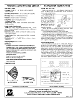
LED LOCATIONS
D4: YELLOW OPERATIONAL STATUS
D3: GREEN RF SIGNAL STRENGTH
D5: RED TROUBLE
DS14: GREEN IP NETWORK TYPE OR QUALITY
DS15 YELLOW IP NETWORK STATE
DS16 RED IP NETWORK TROUBLES
DL: RED DIAGNOSTIC LED
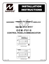
Supervised Arm / Disarm Input
10K
10K
C
Open = Disarmed
Closed = Armed
The EOLR must be installed and located within the control panel housing.
Radio GND
(TB8)
(Radio)
(Alarm Panel)
8 7 9
-or- To StarLink
Terminals
IN2 (TB7)
-or-
IN3 (TB9)
Supervised Fire / Burg Input
10K
10K
C C N/O
Alarm
N/O
TBL*
To StarLink
Terminals
IN2 (TB7)
-or-
IN3 (TB9)
Radio GND
(TB8)
The EOLR must be installed and located within the control panel housing.
(Radio)
(Alarm Panel)
8 7 9
-or-
N/C
*Reverse polarity / energized state.

4 StarLink™ Connect SLE-LTEV-C / SLE-LTEV-Z Alarm Communicators -- Installation Instructions
(radio terminals 12 and 13)
When D606 (red) is flashing 2 = DSC download con-
nection faulted (radio terminals 19 and 20)
SUPPLYING POWER TO THE RADIO
Control panels can provide power through their Auxiliary
Power terminals if the available standby current is reduced
by the SLE standby power. If the control panel Auxiliary
Power is insufficient to power the communicator, a suitably
rated power limited Residential Fire / Commercial Burglary
power supply may be used (such as the model GEMC-
12V2APS).
RADIO INSTALLATION STEPS
STEP 1: ACCOUNT REGISTRATION
Create a new account and register specific StarLink radio
modules at www.NapcoComNet.com. Accounts and mod-
ules registered via the Internet are enabled for activation
within 24 hours.
STEP 2: SELECT A MOUNTING LOCATION
The mounting location should be indoors within the protect-
ed area and selected based on RF performance. It is
HIGHLY recommended that the installer carefully adhere to
the following recommendations BEFORE any wires are
installed.
Generally, high locations are best. DO NOT mount ra-
dio in basements or below grade as unpredictable per-
formance may result.
DO NOT mount the radio in non-climate controlled envi-
ronments (i.e. attics may become extremely hot in sum-
mer, garages may become extremely cold in winter).
Avoid mounting locations within 3 feet of AC power
lines, fluorescent light fixtures, or large metal objects (air
conditioners, metal garage doors, etc.) as these loca-
tions have been shown to have a detrimental effect on
signal strength.
A fair amount of care may be required to mount the ra-
dio so as to achieve an optimal RF path. The installer
should spend as much time as needed to obtain the
highest signal level possible.
a. Before applying power, be sure to connect the
antenna. Temporarily connect power to the ra-
dio from a fully charged 12V (4AH minimum) bat-
tery. DO NOT mount the StarLink radio at this time.
Press Tamper switch to send a signal.
b. Position the unit in the desired mounting location,
with antenna oriented vertically. The signal strength
is displayed by the Green "Signal Strength LED"
labeled "D3" (located at the lower right corner of the
PC board). The LTE (Verizon) radio tower signal
strength may fluctuate from day to day, therefore it
is best to try to find a mounting location where the
LED provides a minimum of 2 blinks.
c. Once a location has been selected based on signal
coverage, permanently secure the unit using #8
screws (not supplied) in the two mounting holes.
When DS15 is flashing slowly:
1 Slow Blink: Ethernet available (must detect
that the CAT5 cable is connected and must be con-
nected to the Internet via customer router, etc.)
2 Slow Blinks: Wi-Fi Station Mode
3 Slow Blinks: Wi-Fi APN Mode (Access Point)
The red LED labeled "DS16" describes the IP network
troubles.
When DS16 is off = No network troubles detected
When DS16 is flashing rapidly = No IP connection
(occurs just after power up while the radio tries to ob-
tain a DHCP IP address
When DS16 is flashing slowly:
1 Slow Blink: No network cable detected
2 Slow Blinks: No network cable access to the
Internet (mutually exclusive with "1 Blink"). If the ra-
dio is configured for only an Ethernet connection (no
Wi-Fi) and the Ethernet cable is connected but the
router is non-functional, the radio will detect the loss
of access to the Internet within a programmable
amount of seconds. The default of 500 seconds (8-
1/3 minutes) is intended to display a trouble to the
installer sooner in case the account is set for 1-hour,
24-hour or 7-day Supervisory Failure
3 Slow Blinks: Ethernet failed to communicate
4 Slow Blinks: Ethernet poll / check-in failure
5 Slow Blinks: Wi-Fi enabled but the SLE-WIFI-
MODULE is not detected
6 Slow Blinks: = No Wi-Fi access to the Internet.
May occur when the Wi-Fi and the network cable
each access the Internet via separate means (for
example two different routers). Note: This indication
may be combined with the "2 Blinks" indication if both
the Wi-Fi and network cable use the same ISP.
7 Slow Blinks: Wi-Fi failed to communicate
8 Slow Blinks: Wi-Fi poll / checkin fail
9 Slow Blinks: Wi-Fi serial data error or no serial
data response
10 Slow Blinks: Wi-Fi Security / Authentication
failed
OTHER LEDs
Labeled "D607" (green) and "D606" (red), these LEDs
indicate the status when connected to a DSC or Honey-
well control panel (when connected to a NAPCO control
panel, both LEDs remain off). The LED labeled "D44" is
not used.
When connected to a Honeywell control panel, D607
(green) flashes once every 5 seconds, and:
When D606 (red) is off = No troubles
When D606 (red) is flashing rapidly = Bootloader mode
When D606 (red) is flashing 1 = Keypad bus fault
When D606 (red) is flashing 3 = Configuration memory
error
When connected to a DSC control panel, D607 (green)
flashes twice every 5 seconds and:
When D606 (red) is off = No troubles
When D606 (red) is flashing rapidly = Bootloader mode
When D606 (red) is flashing 1 = Keypad bus fault

StarLink™ Connect SLE-LTEV-C / SLE-LTEV-Z Alarm Communicators -- Installation Instructions 5
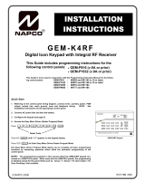
NAPCO CONTROL PANEL PROGRAMMING
To program the central station receiver reporting format,
use PCD-Windows Quickloader download software. Open
the Digital Communications screen, Central Station Receiv-
ers tab, as shown in the following image:
A "Point ID" (also called "Contact ID") receiver format pro-
gramming example:
The radio can transmit to any central station capable of
receiving SIA Contact ID or 4/2 via DACR technology or
the DSC Sur-Gard Model System II or Sur-Gard System V
central station receivers, Bosch D6100IPV6 or Bosch
D6600 Receiver (with ITS-D6686 Ethernet Adapter) via
TCP/IP using standard line security.
Note: A receiver reporting format must be entered for
each telephone number used, but each telephone number
may be assigned a different format.
CAUTION: The installer should always be certain an area
code is programmed into the control panel.
Optional: If you wish the StarLink radio to report a code
and zone number (Contact ID by default) to the central station
in response to a triggered input event, see the table on page
7. Note: These event codes and zone numbers can be
changed from the Management Center screen (located at
http://NapcoNoc2.com).
Programming StarLink Radio Troubles
It is required that if a StarLink radio or control panel trouble is
detected, that it is reported to the central station.
When the StarLink radio detects and sends a trouble to the
control panel, the control panel must be programmed to an-
nunciate this trouble. The radio can detect multiple troubles
as indicated by the "Red Trouble LED" ("D5"). For these
troubles to be annunciated at the control panel, there are
several methods, some of them are configurable at the Man-
agement Center screen (http://NapcoNoc2.com):
Wire the radio PGM1 output to a dedicated control panel
zone (input) to annunciate the trouble (activate a trouble
sounder) when an open is detected. With Napco control
panels, program a dedicated zone for Day Zone, Mini-
sounder on Alarm and No bell on Alarm. Wire the zone as
indicated in the wiring diagrams further in this manual.
WARNING: To ensure user safety and to satisfy FCC
RF exposure requirements, this unit must be installed so
that a minimum separation distance of 60cm (24") is al-
ways maintained between the antenna of the transmitting
device and nearby persons.
STEP 3: WIRING
22-gauge wire may be used if mounted up to 50 feet from
the control panel, and 18-gauge wire should be used for up
to 100 feet. Reference the wiring diagrams further in this
manual. All wiring methods must be performed in accord-
ance with NFPA70, Articles 725, and 800
STEP 4: APPLY POWER
Attach antenna before applying power !
Apply 12 VDC to terminals 1 and 2.
STEP 5: SIGNAL VERIFICATION
After triggering channels, use the StarLink radio Signal Veri-
fication to ensure that the StarLink radio Network has
properly received the signals.
Verify Online: To verify that the signals have been
received by the StarLink radio Network online, go to
http://NapcoNoc2.com, log in with your Username and
Password, enter your Company ID number and the Star-
Link Radio Number, then click Signal Log.
IMPORTANT: Verify that the signals transmitted by the
StarLink radio have been properly received by your central
station before leaving the premises.
NOTE: This equipment has been tested and found to
comply with the limits for a Class B Unintentional Radiator,
pursuant to Part 15 of the FCC Rules. These limits are de-
signed to provide reasonable protection against harmful in-
terference in a residential installation. This equipment gen-
erates, uses, and can radiate radio frequency energy and, if
not installed and used in accordance with the Instruction
Manual, may cause harmful interference to radio communi-
cations. However, there is no guarantee that interference
will not occur in a particular installation. If this equipment
does cause harmful interference to radio or television recep-
tion, which can be determined by turning the equipment off
and on, the user is encouraged to try to correct the interfer-
ence by one of more of the following measures: 1. Reorient
or relocate the receiving antenna; 2. Increase the separation
between the equipment and receiver; 3. Connect the equip-
ment into an outlet on a circuit different from that to which
the receiver is connected; 4. Consult the dealer or an experi-
enced radio/TV technician for help.
Telco Line to Alarm Panel Supervision
A UL Listed 10K ohm EOL resistor (5% tolerance) can be placed across the "house side" of the telephone
line circuit (see wiring diagrams). Use this resistor instead of using a relay on the alarm control panel to trip
an input on the radio to supervise the connection between the alarm control panel telco circuit and the radio.
REMEMBER: Enable the feature "Tip / Ring Wiring Fault Report" in the NOC
(www.NapcoComNet.com) to supervise the telephone line connection to the control panel.

6 StarLink™ Connect SLE-LTEV-C / SLE-LTEV-Z Alarm Communicators -- Installation Instructions
To report the radio trouble to the central station:
1. Program the SLE-LTEV-C/Z (select "Y") for the "Tip/Ring
Wiring Fault Report" feature located in the Advanced
Features screen of the Napco "NOC" (at http://
NapcoNoc2.com).
2. Install a UL Listed 10K EOLR across the control panel
terminals normally intended to be wired to the home tele-
phone if Telco service was used (shown in the wiring
diagram examples).
Note: Some control panels may require a different dura-
tion than the default time of 3 minutes. See also the alter-
nate supervision method described below, "Telco Line to
Alarm Panel Supervision (For Primary Mode Only)".
Supervision Time Schedule Considerations
If a status change (alarm trouble, etc.) is transmitted, the ra-
dio supervision timer is restarted.
For example, if a status change is sent, the next regular su-
pervision transmission will occur at the interval determined
by your rate plan.
For radio models powered by the control panel Aux Power
terminals, wire the radio directly to the PGM1 output of the
control panel (program the radio to report all troubles on
PGM1).
You can also wire to the positive terminal of the dedicated
zone on a GEMC-EZM8. Thus when a radio trouble is de-
tected, the radio PGM activates the control panel zone, and
the control panel generates a trouble.
StarLink Panel / Radio Supervision of Tip/Ring Wiring
We recommend that the StarLink radio connection to the
control panel be supervised with local trouble annunciation
and report to the central station if the Tip/Ring wiring is cut or
shorted.
For local annunciation of radio troubles, the control panel
must be programmed for Telco line supervision that will pro-
duce a local trouble at the premises (refer to control panel
programming).

StarLink™ Connect SLE-LTEV-C / SLE-LTEV-Z Alarm Communicators -- Installation Instructions 7
NOC Originated
Alarms
Contact ID
Event Data
Sent
Pulse Format
Event Code
Sent Initiated By Comments
Supervisory Fail E356 A00 Zn000 99 Automatically by NOC if fail to receive
any signal from StarLink radio within
Supervisory Timeout duration.
For Auto Enroll, uses captured telephone
number, Sub ID and format. For Dealer
Programmed, uses entered telephone
number, Sub ID and format.
Press to Send
Test Signal E601 A00 Zn000 98
Manually by dealer from the Manage-
ment Center Signal Log screen (located
at http://NapcoNoc2.com). Sends test
into CS receiver.
Same comment as above.
Press to Send
Radio Test
Not Applicable
Nothing sent to
CS receiver Not Applicable
Manually by dealer from the Manage-
ment Center Checkins screen (located at
http://NapcoNoc2.com). Sends a com-
mand to the StarLink radio to force a
check-in to the NOC.
----
SIGNALS ORIGINATED AT THE NOC
STARLINK RADIO RELATED EVENT
REPORT CODES (Contact ID by default)
EVENT AREA CONTACT ID PULSE
4/2
CODE ZONE #
IN 1 Fire 0 E110 990 1A
IN 2 Panic 0 E120 992 22
IN 3 Trouble 0 E300 993 F3
Low Battery/Voltage 0 E302 994 F4
Tamper Trouble 0 E341 995 F5
Reboot 0 E625 997 F7
IN 1 CO (Carbon Monoxide) 0 E162 998 18
Panic Alarm* E123
Holdup Alarm* E122
Medical Alarm* E100
24 hour Aux. Alarm* E150
24 hour Aux. Restore* R150
Burg Perimeter Alarm* E131
Burg Interior Alarm* E132
Keypad Holdup Alarm (ambush)* E121
Keypad Panic Alarm* E123
Keypad Emergency Alarm* E140
Opening* E401
Closing* R401
A.C. Trouble* E301
Tel 1 Fail* E351
Fire Polling Report E780 999 F9
Supv Failure Report E788 000 D1 or D2
Tip/Ring Wiring Fault Report E789 000 F2
Path Test Report E602 890 77
*Not generated by the StarLink radio.
COVER TAMPER SWITCH
The SLE series radios in the plastic housings are
provided with a front tamper switch. Note: The tamper
switch on the radio PC board is always functional and
requires no programming.
JUMPER DESCRIPTIONS
Jumper block labeled "X5"; from top to bottom, as
detailed in the following table. Note: Contact ID is
always available in response to a Contact ID
handshake.
The SLE series radios are compatible with 4/2 Pulse
Dialing formats with 10pps, 20pps, and 40pps with and
without checksum, either 1400Hz or 2300Hz
handshake / kissoff. See WI2336LF for table of
formats.
Refer to WI2140 for selecting the required handshake /
kissoff frequency in the NOC (http://NapcoNoc2.com)
setup screens (as required by the control panel).
Jumper Block "X5" Options
Jumper block labeled "X5" contains 5 jumper terminals; from top
(labeled "1") to bottom (labeled "5") as follows:
Jumper ON Jumper
Number Jumper OFF
Not used; do NOT install jumper 1 Not used; do NOT install jumper
4/2 with Checksum Pulse Format 2 Contact ID or 4/2 format without
sum check
Not used; do NOT install jumper 3 Not used; do NOT install jumper
Supervised inputs. EOLR(s)
required, see page 3 4 and 5
Not permitted by UL1610

8 StarLink™ Connect SLE-LTEV-C / SLE-LTEV-Z Alarm Communicators -- Installation Instructions
(STARLINK RADIO HOUSING)
StarLink Radio Terminals
Wiring Diagram for PRIMARY Reporting Configuration
GEM-P816 / GEM-P1632 / GEM-P1664 Control Panels
13 14 15 16 17 18 19 20 21 22 26 27 28 29 23 24 25 ~ ~
(un-polarized)
*Refer to section
"SUPPLYING
POWER".
TIP RING TIP RING
TELCO PHONE
~
2.2K
ZONE (+)
DEDICATED TO GPRS
SUPERVISION
~ ~
Wiring Diagram for PRIMARY Reporting Configuration
GEM-X255 / GEM-P9600 / GEM-P3200 Control Panels
(CONTROL PANEL HOUSING)
13 14 15 16 17 18 19 20 21 22 26 27 28 29 23 24 25 33 30 31 32
Control Panel PC Board
~ ~
*Refer to section
"SUPPLYING
POWER".
TIP RING TIP RING
TEL LINE PHONE
2.2K
(CONTROL PANEL HOUSING)
(STARLINK RADIO HOUSING)
StarLink Radio Terminals
9
10
11
REMOTE
BUS
BLK
GRN
12
YEL
RED
Control Panel PC Board
~
(un-polarized) (un-polarized)
9
10
11
REMOTE
BUS
BLK
GRN
12
YEL
RED
(‒)
TX
RX
(+)
(un-polarized)
ZONE (+)
DEDICATED TO GPRS
SUPERVISION
10K
10K EOLR required when TIP/RING
Wiring Fault Report is enabled in
the Napco "NOC". For optional
local line fault annunciation, enable
the Telco Line Cut Monitor feature
in the control panel programming.
10K
10K EOLR required when TIP/RING Wiring
Fault Report is enabled in the Napco "NOC".
For optional local line fault annunciation,
enable the Telco Line Cut Monitor feature in
the control panel programming.
Note: All end-of-line
resistors must be UL
Listed EOLR for
Residential Fire
applications.
Note: All end-of-line
resistors must be UL
Listed EOLR for
Residential Fire
applications.
/