Page is loading ...

DT8050M DUAL TEC
®
Motion Sensor - Quick Installation Guide
DT8050M DUAL TEC
®
Motion Sensor - Quick Installation Guide (FR)
DT8050M DUAL TEC
®
Motion Sensor - Quick Installation Guide (SP)
DT8050M DUAL TEC
®
Motion Sensor - Quick Installation Guide (PG)
1
6' 9" - 8' 9"
(2.1 - 2.7 m)
7' 6"
(2.3 m)
Optimal
Optimal
Optimal
Optimal
2
3
2
1
3
#6
(3.5 mm)
A
A
A
B B
B B
B B
A
B
#6 x 1 1/4"
(3.5 mm x 32 mm)
X X
4
Microwave Range Adjustment
Réglage de la portée Hyperfréquence
Ajuste del rango de detección Microondas
Ajuste de Alcance Microondas
* Factory default / Réglage usine /
Defecto de fábrica / Padrão de fábrica
ON
LED
*
Not Used
Not Used
Not Used
Not Used
MW
SENSITIVITY
MAX
*
MIN
*
Internal EOL Resistor DIP Switches
Résistance interne EOL commutateur DIP
Interruptores DIP internos EOL Resistor
EOL interno Resistor DIP Switches
EOL
KOhm
ON
1 2.2 5.62
*
DT8050M
AM LED
EOL
PULL
TO DISABLE
LOOK DOWN
LOOK DOWN
ON
OFF
ON
W1
MW
SENSITIVITY
MAX
KOhm
ON
1 2 2.2 5.6

- 2 -
5
24-20 AWG
(0.2-0.52mm2)
2
1
2
Tamper
30 mA
25 VDC
Trouble
30 mA
25 VDC
Power
18 mA
9 - 15 VDC
Alarm
30 mA
25 VDC
LED
0 VDC - Vsupply
1.8 mA max
LED TBL T C V-V+
T NCTBL
9 8 6 4 2 15 37
EOL
KOhm
ON
1 2.2 5.62
EOL
WIRING EXAMPLES / WIRING EXAMPLES / WIRING EXAMPLES
To connect alarm and tamper outputs (NO trouble) to one zone input:
All alarm and tamper events are “alarms” when the system is armed or
“fault” when disarmed.
(FR) To connect alarm and tamper outputs (NO trouble) to one zone
input: All alarm and tamper events are “alarms” when the system is
armed or “fault” when disarmed.
(SP) To connect alarm and tamper outputs (NO trouble) to one zone
input: All alarm and tamper events are “alarms” when the system is
armed or “fault” when disarmed.
(PG) To connect alarm and tamper outputs (NO trouble) to one zone
input: All alarm and tamper events are “alarms” when the system is
armed or “fault” when disarmed.
Zone
COM Ground +12V
Control Panel
Zone
#
LED TBL T C V
-
V
+
T NCTBL
9 8 6 4 2 15 37
Sensor
EOL
KOhm
ON
1 2.2 5.62
EOL
(On-Board, Internal EOLR)
To connect all three outputs (sensor alarm, tamper and trouble) to
one zone input: All alarm, tamper and trouble events are “alarms” when
the system is armed or “fault” when disarmed.
FR) To connect all three outputs (sensor alarm, tamper and trouble)
to one zone input: All alarm, tamper and trouble events are “alarms”
when the system is armed or “fault” when disarmed.
ES) To connect all three outputs (sensor alarm, tamper and trouble)
to one zone input: All alarm, tamper and trouble events are “alarms”
when the system is armed or “f
ault” when disarmed.
PG) To connect all three outputs (sensor alarm, tamper and trouble)
to one zone input: All alarm, tamper and trouble events are “alarms”
when the system is armed or “fault” when disarmed.
Zone
COM Ground
Zone
#+12V
Control Panel
(On-Board, Internal EOLR)
LED TBL T C V
-
V
+
T NCTBL
9 8 6 4 2 15 37
EOL
KOhm
ON
1 2.2 5.62
EOL
Sensor

- 3 -
To connect the sensor alarm output to one zone input and the
tamper and trouble outputs to a second zone input: The alarm relay
is wired to one zone; the tamper and trouble are wired to another zone;
the control panel differentiates alarm conditions from tamper and trouble
conditions.
To connect the sensor alarm output to one zone input and the
tamper and trouble outputs to a second zone input: The alarm relay
is wired to one zone; the tamper and trouble are wired to another zone;
the control panel differentiates alarm conditions from tamper and trouble
conditions.
To connect the sensor alarm output to one zone input and the
tamper and trouble outputs to a second zone input: The alarm relay
is wired to one zone; the tamper and trouble are wired to another zone;
the control panel differentiates alarm conditions from tamper and trouble
conditions.
To connect the sensor alarm output to one zone input and the
tamper and trouble outputs to a second zone input: The alarm relay
is wired to one zone; the tamper and trouble are wired to another zone;
the control panel differentiates alarm conditions from tamper and trouble
conditions.
*
Zone
COM Ground +12V
Control Panel
Trouble
Zone
Alarm
Zone
W1
* Off-Board, External EOLR (Not supplied),
best if installed inside the sensor housing.
LED TBL T C V-V+
T NCTBL
9 8 6 4 2 15 37
Cut
EOL
KOhm
ON
1 2.2 5.62
EOL
Sensor
(On-Board, Internal EOLR)
JUMPER
To connect the sensor alarm, tamper and trouble outputs to three
separate zone inputs: The alarm, tamper and trouble are each wired to
a separate zone; the control panel differentiates alarm, tamper and trouble
conditions.
To connect the sensor alarm, tamper and trouble outputs to three
separate zone inputs: The alarm, tamper and trouble are each wired to
a separate zone; the control panel differentiates alarm, tamper and trouble
conditions.
To connect the sensor alarm, tamper and trouble outputs to three
separate zone inputs: The alarm, tamper and trouble are each wired to
a separate zone; the control panel differentiates alarm, tamper and trouble
conditions.
To connect the sensor alarm, tamper and trouble outputs to three
separate zone inputs: The alarm, tamper and trouble are each wired to
a separate zone; the control panel differentiates alarm, tamper and trouble
conditions.
* *
Zone
COM Ground +12V
Control Panel
Tamper
Zone
Alarm
Zone
Trouble
Zone
Zone
COM
LED TBL T C V
-
V+
T NCTBL
9 8 6 4 2 15 37
W1
Cut
EOL
KOhm
ON
1 2.2 5.62
EOL
* Off-Board, External EOLR (Not supplied),
best if installed inside the sensor housing.
Sensor
(On-Board, Internal EOLR)
6
30 sec
30
0
45
20
10
ON
MW
SENSITIVITY
MAX
MIN
LED
Walk Test Reset
4X
(slowly)
< 4 ft /1.2m
LED Power
Up Walk Test Normal Trouble
Red Slow
Blink
ON
Alarm
ON
Alarm
Fast
Blink
Yellow OFF ON
Microwave
ON
Microwave OFF
Green OFF ON PIR ON PIR OFF

- 4 -
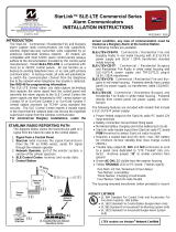
7
Top View
Vue de dessus
Vista Desde Arriba
Vista Superior
Side View
Vue de coté
Vista Lateral
Vista Lateral 0
0.5
1.85
2.3m
PLAN VIEW
ALL ZONES
7’
2 m
0
0
13’
4 m
20’
6 m
27’
8 m
33’
10 m
40’
12 m
7’
2 m
13’
4 m
20’
6 m
27’
8 m
33’
10 m
40’
12 m
7’
2 m
13’
4 m
20’
6 m
27’
8 m
33’
10 m
40’
12 m 46’
14 m
53’
16 m
7’
2 m
0
13’
4 m
20’
6 m
27’
8 m
33’
10 m
40’
12 m
46’
14 m
53’
16 m
A B C D
APPROVAL/ LISTINGS:
• FCC part 15, Class B verified
• IC ICES-003, Class B verified
• UL 639
• ULC S306-03
• SIA-PIR-01 Passive Infrared detector standard features for false alarm immunity.
NOTES:
Product must be tested at least once each year.
For appropriate wiring methods, refer to the National Electrical Code NFPA 70 and the Canadian Electrical Code (where applicable).
Power must be provided by a power-limited UL603 Listed burglar alarm power supply with minimum 4 hours of standby power capability, or from a
power-limited output of a UL Listed burglar alarm control unit with minimum 4 hours of standby power capability.
For the latest documentation and online support information, please go to:
Pour de l’assistance en ligne, visitez :
Para recibir soporte en línea, visite:
Para qualquer informação adicional, contacte:
http://www.security.honeywell.com/hsc/resources/MyWebTech/
For the latest U.S. warranty information, please go to: www.honeywell.com/security/hsc/resources/wa or
Please contact your local authorized Honeywell representative for product warranty information.
Pour obtenir de l'information sur la garantie de ce produit, veuillez communiquer avec le représentant autorisé de Honeywell
de votre région.
Por favor contacte con su distribuidor Honeywell Security para información sobre la garantía del producto.
Contacte o representante autorizado Honeywell local para obter informações relativas a garantia.
2013 Honeywell International Inc. Honeywell and DUAL TEC are registered trademarks of Honeywell International Inc.
All other trademarks are the properties of their respective owners. All rights reserved. Made in China.
P/N 800-15445 12/13 Rev B
2 Corporate Center Drive, Suite 100
P.O. Box 9040, Melville, NY 11747
www.honeywell.com/security
To protect the environment, a detailed installation guide is available on
the Honeywell website – Please consider before printing the document!
FEDERAL COMMUNICATIONS COMMISSION STATEMENTS
The user shall not make any changes or modifications to the equipment unless authorized by the Installation Instructions or User's Manual. Unauthorized changes or modifications
could void the user's authority to operate the equipment.
CLASS B DIGITAL DEVICE STATEMENT
This equipment has been tested to FCC requirements and has been found acceptable for use. The FCC requires the following statement for your information:
This equipment generates and uses radio frequency energy and if not installed and used properly, that is, in strict accordance with the manufacturer's instructions, may cause
interference to radio and television reception. It has been type tested and found to comply with the limits for a Class B computing device in accordance with the specifications in
Part 15 of FCC Rules, which are designed to provide reasonable protection against such interference in a residential installation. However, there is no guarantee that interference
will not occur in a particular installation. If this equipment does cause interference to radio or television reception, which can be determined by turning the equipment off and on, the
user is encouraged to try to correct the interference by one or more of the following measures:
• If using an indoor antenna, have a quality outdoor antenna installed.
• Reorient the receiving antenna until interference is reduced or eliminated.
• Move the radio or television receiver away from the receiver/control.
• Move the antenna leads away from any wire runs to the receiver/control.
• Plug the receiver/control into a different outlet so that it and the radio or television receiver are on different branch circuits.
• Consult the dealer or an experienced radio/TV technician for help.
INDUSTRY CANADA CLASS B STATEMENT
This Class B digital apparatus complies with Canadian ICES-003.
Cet appareil numérique de la classe B est conforme à la norme NMB-003 du Canada.
FCC / IC STATEMENT
This device complies with Part 15 of the FCC Rules, and RSS210 of Industry Canada. Operation is subject to the following two conditions: (1) This device may not cause harmful
interference, and (2) This device must accept any interference received, including interference that may cause undesired operation.
Cet appareil est conforme à la partie 15 des règles de la FCC & de RSS 210 des Industries Canada. Son fonctionnement est soumis aux conditions suivantes: (1) Cet appareil ne
doit pas causer d’interférences nuisibles. (2) Cet appareil doit accepter toute interférence reçue y compris les interférences causant une réception indésirable.
Zones / Zones / Zonas / Zonas
A
2
Look-down / Basses / Vista Zona 0 /
Vigilância inferior
B
12
Lower / Courtes / Cercana/ Mais baixas
C
10
Intermediate / Intermédiaires / Intermedia /
Intermédias
D
36
Long / Longues / Largo Alcance /
Longo alcance
/