12
EN
Ensure that the emergency handle is
not inserted in the product and turn
the mode selector to the AUT position.
LED “Power” Green: ON
LED Manuel/Default: OFF
___________________________________________________________
STEP 6A
Automatic Operation
To enable control, close contact 312 with 317.
To force the product to 0 position/OFF bridge
the contact 313 with 317.
For contactor logic bridge contact 316 with 317.
To operate: close the contact corresponding to
the desired position.
maintened
ordre I
position I
ordre 0
position 0
ordre II
position II
Contactor logicImpulse logic
Check
Whilst in manual mode, check the
wiring and if ok power up the
product.
LED “Power” Green: ON
LED “Source” Green: ON
(
I
/
II
or
I
II
)
LED Manuel/Defaut Red
102 -
N
101 -
L
Aux 1
202 -
L
201 -
N
Aux 2
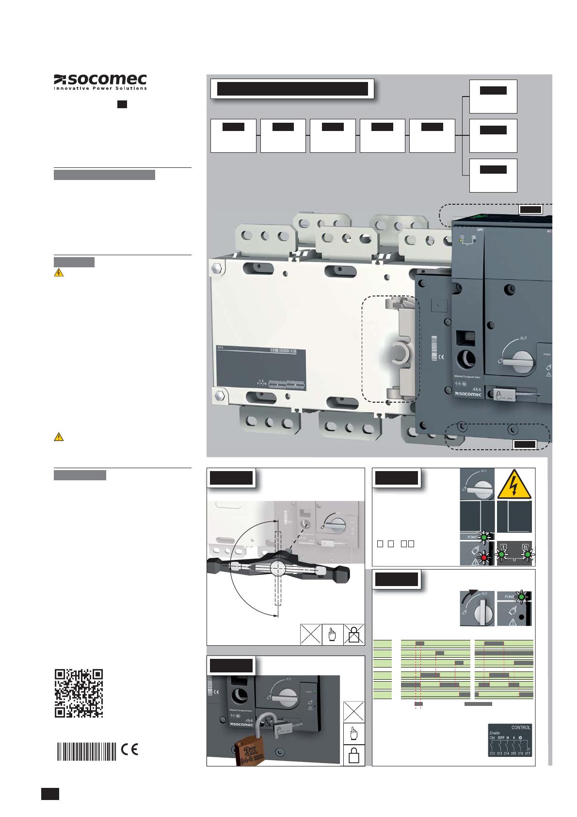
STEP 5
ATyS d
Motorised Source Changeover Switch
STEP 1
Cabinet / Back Plate
Installation
STEP 3
COMMAND /
CONTROL terminal
connections
STEP 2
Connecting the
POWER section
STEP 4
Power SUPPLY
terminal connections
STEP 5
CHECK
Installation and Commissioning
STEP 6A
Control by an external
order (AUTO)
STEP 6C
Padlocking
STEP 6B
Emergency Manual
Operation
Preliminary operations
packaging:
■ Packaging and contents are in good condition.
■ The product reference corresponds to the order.
■ Contents should include:
Qty 1 x ATyS d
Qty 1 x Emergency handle and fixing clip
Quick Start instruction sheet
Warning
Risk of electrocution, burns or injury to persons and /
or damage to equipment.
This Quick Start is intended for personnel trained in the
installation and commissioning of this product. For further
the SOCOMEC website.
■ This product must always be installed and commissioned
■
performed by trained and authorised personnel.
■ Do not handle any control or power cables connected to
on the product, directly through the mains or indirectly
through external circuits.
■
■ Ensure that no metal objects are allowed to fall in the
cabinet (risk of electrical arcing).
follow these safety instructions may expose the user and
others to serious injury or death.
■ In case the product is dropped or damaged in any way it
is recommended to replace the complete product.
Accessories
■ Bridging bars and connection kits.
■
■
■ Mounting spacers to raise the product x 10mm.
■ Phase barriers.
■ Terminal shrouds.
■ Terminal screens.
■ Auxiliary contacts (Additional).
■
■
■ Door escutcheon frame.
■ Control relay ATyS C30 + D10 or D20.
■
■ ATyS D10 Interface (remote display).
For further details refer to the product instruction manual
under chapter "Spares and Accessories"
541 989 D - 02/14 - EN
QUICK START
EN
Non contractual document.
Sub
ect to chan
e without notice.
Clip for
storage of
the
emergency
handle
STEP 3
www.socomec.com
To download, brochures, catalogues and technical manuals:
Printing informations: 1 color Black. White paper 90g/m
2
.
STEP 6B
STEP 6C
Manual Operation
Padlocking Mode
(as standard : in position O)
AUT
90°
90°
II
I
0
STEP 4


