FA00324-EN
E
ng
li
s
h
E
N
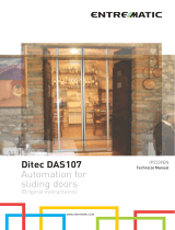
INSTALLATION MANUAL
SIPARIO T
SLIDING DOOR OPERATOR

p.
2
2 - Manual code:
FA00324-EN
FA00324-EN v.
2
2 - 12/2016 © CAME S.p.A. - The contents of this manual may be revised at any time, and without notice.
WARNING!
important safety instructions for people:
READ CAREFULLY!
Danger of hand crushing
Danger! High voltage.
Premise
• Employ this product only for the use for which it was expressly made. Any
other use is dangerous. CAME S.p.A is not liable for any damage caused by
improper, wrongful and unreasonable use • The safety of this product and its
proper fi tting depends, therefore, on respecting its technical characteristics
and proper fi tting, to be done in state-of-the-art fashion, and under safe
conditions as expressly explained in the literature that comes with the product.
• Keep these warnings together with the installation and operation manuals
that come with the operator.
Before installing
(do not continue until you have complied with all safety provisions)
• Fitting and testing must be be only performed by qualifi ed technicians. Laying
the cables, installation and testing must follow state-of-the-art procedures as
dictated by regulations • Before beginning any operation it is mandatory to
carefully read all instructions improper installation may result in serious harm
to people and things. • Make sure the door or leaf is in good mechanical
state, balanced and aligned, and that it opens and closes properly. Also, install
suitable protections if needed as well as additional safety sensors • If the
operator is to be installed at a height of over 2.5 m from the ground or other
access level, make sure you have any necessary protections and/or warnings
in place • If any pedestrian openings are fi tted into the operator, there must
also be a a system to block their opening while they are moving • Make sure
that the opening automated door or gate cannot entrap people against the
fi xed parts of the operator • Do not install the operator upside down or onto
elements that could yield and bend. If necessary, add suitable reinforcements
to the anchoring points • Do not install door or gate leaves on tilted surfaces •
Make sure any sprinkler systems cannot wet the operator from the ground up
• Make sure the temperature range shown on the product literature is suitable
to the climate where it will be installed as explained in the manual.
Installing
• Suitably section o and demarcate the entire installation site to prevent
unauthorized persons from entering the area, especially minors and children
• Be careful when handling operators that weigh over 20 kg. If need be, use
proper safety hoisting equipment • The CE-marked safety devices (photocells,
stepping plates, sensitive safety-edges, emergency buttons, and so on), must
be fi tted in compliance with the regulations in e ect and according to state-
of-the-art criteria, taking into account the environment, the type of required
service and of the working forces applied to moving leaves. Any shearing
or conveying points must be sensor-protected • Any residual risks must be
pointed out to end users and highlighted with pictograms as provided by the
law. • All opening commands (that is, buttons, key switches, magnetic readers,
and so on) must be installed at least 1.85 m from the perimeter of the gate's
working area, or where they cannot be reached from outside the gate. Also, any
direct commands (buttons, touch panels, and so on) must be installed at least
1.5 m from the ground and must not be reachable by unauthorized persons
• The automatic pedestrian closing must visibly show its identifi cation data.
• Before connecting the main power supply make sure that the identifi cation
data correspond to the those of the network • The automatic pedestrian
closing must be connected to an e ective regulation grounding system •
The manufacturer declines any liability for using non-original products; which
would result in warranty loss • All maintained action commands, must be
fi tted in places from which the moving gate leaves and transit and driving
areas are visible • Apply, if missing, a permanent sign showing the position
of the release device • Before delivering to the users, make sure the system
is EN 12453 and EN 12445 standard compliant (regarding impact forces), and
also make sure the system has been properly adjusted and that any safety,
protection and manual release devices are working properly • Apply Warning
Signs where necessary and in a visible place.
Special user-instructions and recommendations
• Keep gate operation areas clean and free of any obstructions. Make sure the
photocell's operating fi eld is clear of any obstructions • Do not allow children
to play with fi xed commands, or to loiter in the gate's maneuvering area.
Keep any remote control transmitters or any other command device away
from children, to prevent the operator from being accidentally activated.The
apparatus may be used by children of eight years and above and by physically,
mentally and sensorially challenged people, or even ones without any
experience, provided this happens under close supervision or once they have
been properly instructed to use the apparatus safely and about the potential
hazards involved. Children must not play with the apparatus. Cleaning and
maintenance must not be done by children, unless properly supervised •
Frequently check the system for any malfunctions or signs of wear and tear
or damage to the moving structures, to the component parts, all anchoring
points, including cables and any accessible connections. Keep any hinges,
moving joints and slide rails properly lubricated • Perform functional checks
on the photocells and sensitive safety edges, every six months. Constantly
clean the photocells' glass covers using a slightly water-moistened cloth; do
not use solvents or chemicals that could damage the devices • If repairs or
modifi cations are required to the system, release the operator and do not use
it until safety conditions have been restored • Cut o the power supply before
releasing the operator for manual openings and before any other operation,
to prevent potentially hazardous situations. Read the instructions • If the
power supply cable is damaged, it must be replaced by the manufacturer or
authorized technical assistance service, or in any case, by similarly qualifi ed
persons, to prevent any risk • It is FORBIDDEN for users to perform any
OPERATIONS THAT ARE NOT EXPRESSLY REQUIRED OF THEM AND WHICH ARE
NOT LISTED in the manuals. For any repairs, modifi cations and adjustments
and for extra-ordinary maintenance, CALL TECHNICAL ASSISTANCE • Log the
jobs and checks into the periodic maintenance log.
Additional special recommendations for everyone
• Keep away from hinges and mechanical moving parts • Do not enter the
operator's area of operation when it is moving • Do not counter the operator's
movement as this could result in dangerous situations • Always pay special
attention to any dangerous points, which have to be labeled with specifi c
pictograms and/or black and yellow stripes • When using a selector switch or
a command in maintained actions, keep checking that there are no persons
within the operating range of any moving parts, until the command is released
• The gate may move at any time and without warning • Always cut o the
power supply before performing any maintenance or cleaning.

T
H
P
p.
3
3 - Manual code:
FA00324-EN
FA00324-EN v.
2
2 - 12/2016 © CAME S.p.A. - The contents of this manual may be revised at any time, and without notice.
LEGEND OF SYMBOLS AND GLOSSARY
This symbol shows which parts to read carefully
This symbol shows which parts describe safety issues
This symbol shows which parts to tell users about
T = Overall operator length
LT = Beam length
LC = Profile cover length
PA = Attaching-profile length
As = Overall length of a single door-leaf complete with gaskets
Vp = Passage span
S = Overlapping between door-leaves or between moving door-leaves and fixed parts (masonry work)
REFERENCE REGULATIONS
Came S.p.A. is certified for the: ISO 9001 quality and ISO 14001 environmental management systems.
This product complies with the current regulations mentioned in the declaration of conformity.
DESCRIPTION
Operator for telescopic sliding door with 1+1 or 2+2 leaves, with system of rollers and door-leaf towing.
Any installation and/or use other than that specified in this manual is forbidden.
Limits to use
Model SIPARIOT1D - SIPARIOT1S SIPARIOT2
Minimum door-leaf length (mm) 520 + 520 (460 + 460) + (460 + 460)
Maximum beam length (mm) 6700 6700
Maximum gate-leaf weight (kg) 100 + 100 (50 + 50) + (50 + 50)
Minimum overlapping of gate-leaves (mm) 20 20
Dimensions (mm)
Model SIPARIOT1D - SIPARIOT1S SIPARIOT2
T min 1550 2710
T max 6729 6729
H100100
P230230
Technical data
Type SIPARIOT1 - SIPARIOT2
Protection rating (IP) 40
Power supply (V - 50/60 Hz) 120 - 230 AC
Power supply motor (V) 24 DC
Draw (A) 5.3
Motor power (W) 220
Electroblock power (W) 15
Control panel and accessories' consumption (W) 18
Maximum maneuvering speed (m/s) 0.8
Duty cycle INTENSIVE USE
Operating temperature (°C) -20 ÷ +55
Thrust (kg) 5
The maximum leaf length depends on: a) the type of application, and, b) any overlapping of leaves, and of moving leaves and fixed
parts (see EXAMPLE APPLICATIONS paragraph).

4
2
3
1
5
5
6
7
8
9
99
9
9
9
9
10
11
12
13
14
15 3
16
17
18
19
20
21
21
22
23
23
24
p.
4
4 - Manual code:
FA00324-EN
FA00324-EN v.
2
2 - 12/2016 © CAME S.p.A. - The contents of this manual may be revised at any time, and without notice.
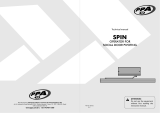
1. Left side plug
2. Hooking profile
3. Spring pin for profile cover
4. Closing stop
5. Mechanical door-leaf stop
6. Belt return
7. Belt
8. Brush
Description of parts
9. Roller
10. Belt hook
11. Recess for additional batteries
12. Profile cover
13. Control board
14. Gearmotor
15. Transformer
16. Profile cover support lever
17. Switch
18. Release lever
19. Fuse holder
20. Right side plug
21. Towing bracket coupling
22. Beam fastening coupling
23. Towing braket
24. Beam

T
SS
Vp
S
T
Vp
As
As
T
SS
Vp
T
Vp
As
As
T
SS
S
Vp
S
As
T
Vp
As
As
LT
p.
5
5 - Manual code:
FA00324-EN
FA00324-EN v.
2
2 - 12/2016 © CAME S.p.A. - The contents of this manual may be revised at any time, and without notice.
Applicative examples
OPERATOR FOR TELESCOPIC SLIDING DOOR WITH 2+2 LEAVES
As (Vp / 4) + S
LT Vp + (2 x As)
T LT + 29 mm
OPERATOR FOR TELESCOPIC SLIDING DOOR WITH 1+1 LEAVES
OVERLAPPING ON BOTH SIDES
As (Vp + 3 x S) / 2
LT Vp + As + S
T LT + 29 mm
OPERATOR FOR TELESCOPIC SLIDING DOOR WITH 1+1 LEAVES
OVERLAPPING ONLY ON ONE SIDE
As (Vp + 2 x S) / 2
LT Vp + As
T LT + 29 mm

p.
6
6 - Manual code:
FA00324-EN
FA00324-EN v.
2
2 - 12/2016 © CAME S.p.A. - The contents of this manual may be revised at any time, and without notice.
001SIPARIOT2
Operator for double telescopic sliding door (2+2 leaves), complete
with end caps.
001SIPC
Anodized aluminum protective carter, with dust protecting brush
and hinges.
001SIPTF
Front frame made of anodized natural aluminum.
001SIPP (optional)
Operator hooking frame made of anodized aluminum for fastening
to the wall.
List of components
001SIPARIOT1D
Operator for right-hand telescopic sliding door (1+1 leaves),
complete with end caps.
001SIPCG
Rough aluminum protective carter, with dust protecting brush and
hinges.
001SIPARIOT1S
Operator for left-hand telescopic sliding door (1+1 leaves),
complete with end caps.
001SIPTP
Back frame made of anodized natural aluminum.

CAME
32°C
10:55
1
2
5
3
4
8
7
7
6
9
10
11
p.
7
7 - Manual code:
FA00324-EN
FA00324-EN v.
2
2 - 12/2016 © CAME S.p.A. - The contents of this manual may be revised at any time, and without notice.
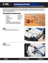
Standard installation
1. Operator
2. Radar
3. Keypad selector
4. Volumetric touch sensor
5. Features selector
6. Transceiver features selector
7. Microphotocells
8. Sensitive floor-plate
9. Release lever
10. Safety box with release handle
11. Release device
GENERAL INSTRUCTIONS FOR INSTALLING
Only skilled, qualified staff must install this product.
Preliminary checks
Before beginning the installation, do the following:
• Set up a dual pole cut off switch with minimum contact openings of 3 mm, and section-off the power supply;
• Set up suitable tubes and conduits for the electric cables to pass through, making sure they are protected from any mechanical damage;
• Make sure that any connections inside the container (ones that ensure continuity to the protection circuit) are fitted with additional
insulation with respect to those of other electrical parts inside;
Tools and materials
Make sure you have all the tools and materials you will need for installing in total safety and in compliance with applicable regulations. The
figure shows some of the equipment installers will need.

1
9
60
5149
30
105 ÷ 109
67 17 16
2
p.
8
8 - Manual code:
FA00324-EN
FA00324-EN v.
2
2 - 12/2016 © CAME S.p.A. - The contents of this manual may be revised at any time, and without notice.
Depending on the distance between ceiling and passage width, the operator may be fastened in two ways:
- if the distance between ceiling and passage width is less than 110 mm, fasten the beam to the wall.
- if the distance between ceiling and passage width is more than 110 mm, fasten the beam to the wall or use the hooking profi le. In the latter
case, fastening the beam is simplifi ed.
INSTALLATION
The following illustrations are just examples, in that the space available for fastening the operator and accessories varies depending on the
overall dimensions. It is up to the installer/fitter, therefore, to choose the most suitable solution.
The operator must be mounted by at least two people. Use proper hoisting gear to transport and position the operator.
Check before fastening the beam
Cable types and minimum thicknesses
Connection Cable type Cable length
1 < 10 m
Cable length
10 < 20 m
Cable length
20 < 30 m
Control panel power supply 230 V AC
FROR CEI 20-22
CEI EN
50267-2-1
3G x 1.5 mm23G x 2.5 mm23G x 4 mm2
Command and safety device 2 x 0.5 mm2
Photocell receivers (DIR, DELTA) 4 x 0.5 mm2
Photocell transmitters (DIR, DELTA) 2 x 0.5 mm2
Photocell transmitters and receivers (SIPA 08-09) SHIELDED (supplied) max 6 m
Antenna RG58 max 10 m
Paired or alternate connection CAT 5 - U/UTP - AWG 24 max 100 m
Connection to the CRP (Came Remote Protocol) CAT 5 - U/UTP - AWG 24 max 1000 m
Metal mass detector (see product literature)
If cable lengths differ from those specified in the table, establish the cable sections depending on the actual power draw of the connected devices and
according to the provisions of regulation CEI EN 60204-1.
For multiple, sequential loads along the same line, the dimensions on the table need to be recalculated according to the actual power draw and distances. If
connecting products that are not contemplated in this manual, see the literature accompanying said products
(mm)
(mm)
min
min
min
max

105 ÷ 109
Ø 8
40
40 125
250
1
2
3
250
250
250
250
250
4
PA
LC
p.
9
9 - Manual code:
FA00324-EN
FA00324-EN v.
2
2 - 12/2016 © CAME S.p.A. - The contents of this manual may be revised at any time, and without notice.
Without hooking profi le - Level the beam and mark the drilling points on the wall .
Drill the marked points, fi t the anchors .
Fasten the beam to the wall .
Tracing the holes and fastening the beam
The following installation indications refer to a s 2+2 leaf system. These indications can be adapted to a 1+1 leaf system.
If necessary, cut the hooking frame and frame cover using the formulas shown below.
Measuring and cutting the hooking profile and profile cover to measure
PA = T - 100 mm LC = T - 97 mm

Ø 8 4
7
6
5
Ø 8
1
2
150
3
8
p.
10
10 - Manual code:
FA00324-EN
FA00324-EN v.
2
2 - 12/2016 © CAME S.p.A. - The contents of this manual may be revised at any time, and without notice.
With hooking profi le - Level the hooking profi le and mark the drilling holes on the wall; the hooking profi le is preperforated.
Drill the marked holes , fi t the anchors and fasten the profi le using bolts and washers .
Hook the beam to the profi le and mark a drilling point on the wall , remove the beam , drill and fi t the anchors .
Hook the beam to the profi le and fasten it to the wall .

Q
Q
Q
Q
Y
Q
RR
Q
RR
RR
Q
Y
Q
RR
Q
p.
11
11 - Manual code:
FA00324-EN
FA00324-EN v.
2
2 - 12/2016 © CAME S.p.A. - The contents of this manual may be revised at any time, and without notice.
Important assessment criteria and solutions to adopt before making the leaves
Glass door-leaves
Check the safety distances between the
sliding leaves and fi xed parts as shown in
the drawing.
QRY
≤ 8 mm ≤ 0 mm ≤ 0 mm
> 8 mm ≥ 25 mm ≥ 25 mm
If the safety distances are not
respected, this must be warned with
signs in the danger areas!
Framed door-leaves
Check the safety distances between the
sliding leaves and fi xed parts as shown in
the drawing.
QRY
≤ 8 mm ≤ 0 mm ≤ 0 mm
> 8 mm ≥ 25 mm ≥ 25 mm
If the safety distances are not
respected, this must be warned with
signs in the danger areas!

10
L - 2
L
100
18
ø 8,5
23
101
min 300
ø 16
± 6
V
70
53 17
40
16
V
20
16
34
80
17
20
ø 4,8
21,5
70
53 17
40
16
44
001MA7370
001MA7470
001MA7570
001MA7353
001MA7453
001MA7553
LL
001MA7380
001MA7480
001MA7580
123
333333
1
21
2
12
23
18
101
100
Y
H
0÷30
1
2
3
60
9
30 20
6
p.
12
12 - Manual code:
FA00324-EN
FA00324-EN v.
2
2 - 12/2016 © CAME S.p.A. - The contents of this manual may be revised at any time, and without notice.
Drilling hole distances for glass and upper profi le
Glass door-leaves
YHeight from the ground for fastening the beam
HHeight of passage width
VHeight of glass
Y = H + (0 ÷ 30 mm)
V = Y - 73 mm
(mm)
min
min

I
10
Y
H
0÷30
± 6
60
40
26,5
20
20
2
LL
001MA7371
001MA7471
001MA7571
001MA7351
001MA7451
001MA7551
1
222222
111111
2
1
2
9
6
p.
13
13 - Manual code:
FA00324-EN
FA00324-EN v.
2
2 - 12/2016 © CAME S.p.A. - The contents of this manual may be revised at any time, and without notice.
Fastening the upper hooking profi le
Framed door-leaves
YHeight from the ground for fastening the beam
HHeight of passage width
IHeight of framed leaf
Y = H + (0 ÷ 30 mm)
I = Y - 31 mm
(mm)
min
min

2
1
2
40
10
40 10
AB C D
p.
14
14 - Manual code:
FA00324-EN
FA00324-EN v.
2
2 - 12/2016 © CAME S.p.A. - The contents of this manual may be revised at any time, and without notice.
Telescopic sliding door with 2+2 leaves
Assemble the rollers to the brackets. Leave the
screws a bit loose. .
Fit the rollers into the upper hooking profi le .
Perform this operation on all of the system's
door-leaves.
Place the rollers as shown in the
fi gure and fasten the screws to the
brackets.

1
1
AD
p.
15
15 - Manual code:
FA00324-EN
FA00324-EN v.
2
2 - 12/2016 © CAME S.p.A. - The contents of this manual may be revised at any time, and without notice.
Fasten the anti-derailing device to the rollers.
Leave the nuts loose.
Door leaf . Door leaf .
Assemble the towing components onto both door leaves.
Fasten the brackets to the rollers ;

2
1
3
2
3
4
p.
16
16 - Manual code:
FA00324-EN
FA00324-EN v.
2
2 - 12/2016 © CAME S.p.A. - The contents of this manual may be revised at any time, and without notice.
Adjust the tautness of the cable by turning the adjusting screw
. Tighten the screws .
Calculate the cable length (As x 2) + 265 mm.
Fit and fasten the cable ends into the fastening coupling onto the beam .
Fit the cable into the towing bracket coupling .
Fit and fasten the other end of the cable into the beam fastening coupling
.

2
1
2
B C
p.
17
17 - Manual code:
FA00324-EN
FA00324-EN v.
2
2 - 12/2016 © CAME S.p.A. - The contents of this manual may be revised at any time, and without notice.
Telescopic sliding door with 1+1 leaves
Assemble the rollers to the brackets. Leave
the screws a bit loose. .
Fit the rollers in to the upper hooking profi le
Perform this operation on both of the
system's door leaves .
Fasten the anti-derailing device and the belt-hooking bracket to the rollers.
Leave the nuts loose.

40
10
40 40
AB
2
3
1
3
4
1
p.
18
18 - Manual code:
FA00324-EN
FA00324-EN v.
2
2 - 12/2016 © CAME S.p.A. - The contents of this manual may be revised at any time, and without notice.
RIGHT-SIDE OPENING
Place the rollers as shown
in the fi gure and fasten the bracket
screws.
Assemble the towing components onto the door leaf .
Fasten the brackets to the rollers ;
Fit and fasten the cable end into the beam fastening coupling ;
Fit the cable into the towing bracket coupling ;
Fit and fasten the other end of the cable into the beam fastening
coupling .
Fasten the anti-derailing device
and the belt-hooking bracket to the
rollers.
Leave the nuts loose.

2
1
4
1
3
5
A
B
10
40
40 40
p.
19
19 - Manual code:
FA00324-EN
FA00324-EN v.
2
2 - 12/2016 © CAME S.p.A. - The contents of this manual may be revised at any time, and without notice.
LEFT-SIDE OPENING
Place the rollers as shown
in the fi gure and fasten the bracket screws.
Assemble the towing components and the belt hooking bracket onto the door-leaf .
Fasten the brackets to the rollers ;
Fit and fasten the cable end into the beam fastening coupling ;
Assemble the towing hook, belt attachment support and belt attachment ;
Fit the cable into the towing bracket coupling ;
Fit and fasten the other end of the cable into the beam
fastening coupling
Fasten the anti-derailing
device onto the rollers.
Leave the nuts loose.

5
2
45
1
3
OK
6
1
1
2
2
p.
20
20 - Manual code:
FA00324-EN
FA00324-EN v.
2
2 - 12/2016 © CAME S.p.A. - The contents of this manual may be revised at any time, and without notice.
Fastening and aligning door leaves A and D
Fit the door leaves into the beam .
To fasten the door leaves, hoist the anti-derailing device
and tighten the screw .
The following installation indications refer to a s 2+2 leaf system. These indications can be adapted to a 1+1 leaf system.
Manually move the door leaves towards the center
being careful that the towing brackets do not hit
against the central support .
Check that the door leaves are level to ensure proper sliding
along the rail . If necessary, , loosen the two roller
screws , adjust the inclination by turning the screw on the
eccentric adjuster on each roller . Tighten the screws
including the headless screw.
Aligning 1
Page is loading ...
Page is loading ...
Page is loading ...
Page is loading ...
Page is loading ...
Page is loading ...
Page is loading ...
Page is loading ...
Page is loading ...
Page is loading ...
Page is loading ...
Page is loading ...
Page is loading ...
Page is loading ...
Page is loading ...
Page is loading ...
/