Page is loading ...


p.
2
2 - Manual code:
119 P M 9 9
119PM99 ver.
2.0
2.0 07/2011 © CAME Cancelli Automatici S.p.a. - The data and information in this manual may be changed at any time and without obligation on the part of Came Cancelli Automatici S.p.a. to notify said changes.
ENGLISH
Index
Legend of symbols and glossary p. 4
Intended use and limits to use p. 4
Intended use p. 4
Limits to use p. 4
Description p. 5
List of Sipario Kit components p. 5
List of Sipario components p. 6
Description of parts p. 7
Standard installation p. 8
Technical data p. 8
Installation p. 9
Preliminary checks p. 9
Tools and equipment p. 9
Installation example p. 9
Measuring and custom cutting the track-beam and frame covers p. 10
Drilling holes in the track-beam p. 11
Marking the holes p. 12
Seals and dust-brush p. 13
Fitting the fastening strip for the card and belt return wheel p. 13
Fitting the gearmotor assembly p. 14
Fitting the mechanical stop p. 14
Fitting the endcaps p. 14
Anchoring the track-beam p. 15
Glass door-frame patterns p. 16
Framed door patterns p. 17
Fitting the hanging wheels, anti-derailing system and belt clamp for DOUBLE-LEAF siding doors p. 18
Fitting the hanging wheels, anti-derailing system and belt clamp for ONE-LEAF sliding doors p. 19
Fitting the door leaves p. 20
Check door-leaf height and alignment p. 21
Fastening the guide sleds p. 22
Fitting and fastening the belt p. 23
Adjusting belt tautness p. 24
Fitting the card assembly p. 25
Assembling and fastening the profi le covers p. 26
Card descriptio p. 28
Power supply connection terminals p. 28
Types and thickness of cables p. 28
Accessories connection terminals p. 29
Functions selection via DIP-switches p. 29
Accessories connections on the card p. 30
LED-light table p. 30
Start up p. 31
Compass function p. 32
Functioning p. 32
Specifi c connections for compass system p. 33
Coupled function (for passage widths greater than 3350 mm) p. 34
Functioning p. 34
Specifi c connections p. 34
Safety instructions p. 35
Maintenance p. 35
Periodic maintenance p. 35
Extraordinary maintenance p. 36
Troubleshooting p. 37
Dismantling and disposal p. 38
CE Compliance statement p. 39

p.
3
3 -
Manual code:
119 P M 9 9
119PM99 ver.
2.0
2.0 07/2011
© CAME Cancelli Automatici S.p.a. - The data and information in this manual may be changed at any time and without obligation on the part of Came Cancelli Automatici S.p.a. to notify said changes.
ENGLISH
WARNING!
important safety instructions:
READ THIS PART CAREFULLY!
Introduction
• This product is only intended to be used for the purpose it was
designed. Any other use is therefore improper and dangerous. La
CAME cancelli automatici s.p.a. is not liable for any damage due to
improper, erroneous and unreasonable use • Keep these warnings
together with the installation and users' manual for the automation
system.
Before installing
(check what's there: if the outcome is negative, refrain from conti-
nuing until you are compliant with safety standard)
Check that the part being automated is in proper working order, that
it is balanced and aligned, and that it opens smoothly. Make sure
you have suitable mechanical stops. If the operator will be installed
less than 2.5 m from the floor or from any other access level, check
whether you need additional protections and/ or warnings. With
pedestrian doors framed into the doors that will be automated, a
system must be in place to block their opening during movement.
Make sure the opening of the automated door leaf does not cause
any trapping situations involving any surrounding fixed parts. Do
not install the operator upside down or on any elements that may
bend. If necessary, add suitable reinforcements at the fastening
points. Do not fit onto door leafs that are installed on a slope, only
on level ground. Check that any watering devices cannot wet the
gearmotor from the bottom upwards.
Installation
Properly demarcate the entire site to prevent any unwanted access
by unauthorised personnel to the working area, especially children
and minors. Be careful when handling operators that weigh more
than 20 kg (see installation manual). If such is the case, make sure
you have proper hoisting equipment. All opening commands (but-
tons, key selectors, magnetic card readers, an so on). must be in-
stalled at least 1.85 m from the gate's area of movement, or so that
they are unreachable from the outside. Also, the direct commands
(button or touch) must be installed at least 1.5 m high and not re-
achable by the public. All "maintained action" commands must be
placed where the moving door leaves and transit areas are comple-
tely visible. If missing, affix a permanent tag showing the position
of the release device. Before delivering to the end user, check that
the operator complies with Standard EN 12456 (impact testing),
making sure the operator is properly set and adjusted and that all
safety and protection devices and manual release work properly.
Affix the Warning Signs in places that are clearly visible, where
necessary (such as the gate tag).
Instructions and special recommendations for users
Keep gate-operating are free of any obstacles. Keep the photocells'
range of operation free of vegetation. Do not allow children to play with
the fixed command devices, or in the area of operation of the gate.
Keep the remote control devices (transmitters) away from children.
Check the system frequently, for any anomalies and signs of wear and
tear or damage to the mobile structures, the component parts of the
operator, all fastening points and devices, the cable and any acces-
sible connections. Keep any jointed parts like hinges lubricated and
clean of debris and the guide-sleds free of any friction. Perform fun-
ctional checks to the photocells and sensitive edges every six months.
Ensure proper cleaning of the glass on the photocells (use a slightly
damp cloth); do not use solvents or other chemical products). If repai-
rs or changes to the system settings become necessary, release the
operator do not use it until all safety conditions are restored. Cut the
main power supply before releasing the operator to perform manual
openings.
Check the instructions. It is FORBIDDEN for users to perform ANY
OPERATIONS THAT ARE NOT EXPRESSLY REQUESTED OF SAID
USERS in the manuals. For repairs, changes to the settings and extra-
ordinary maintenance, CALL FOR TECHNICAL ASSISTANCE. Enter any
interventions in the periodic maintenance log.
Special instructions and recommendations for everyone
Keep away from the hinges and any moving mechanical parts. Stay
out of the operating range of the operator while it is moving. Do not
oppose the movement of the operator as this may result in danger. Al-
ways be careful around the dangerous parts, which must be properly
indicated with warning signs and black and yellow stripes. When using
a selector switch or a maintained-action mode command, keep che-
cking that no persons come within the operating range of the moving
parts, until the command is released. The gate may move at any mo-
ment without warning. Always cut off the main electric power supply
before performing any cleaning or maintenance.

T
H
P
Vp
A
T
A
T
SS
VpSS
p.
4
4 - Manual code:
119 P M 9 9
119PM99 ver.
2.0
2.0 07/2011 © CAME Cancelli Automatici S.p.a. - The data and information in this manual may be changed at any time and without obligation on the part of Came Cancelli Automatici S.p.a. to notify said changes.
ENGLISH
Legend of symbols and glossary
Intended use and limits to use
Intended use
Limits to use
This symbol means parts must be read carefully.
This symbol means the parts describe safety issues.
This symbol tells you what to notify to the user.
The Sipario operator is engineered and built by CAME Cancelli Automatici S.p.A. in compliance with current safety standards for automating
single or double sliding doors.
Any installation or use other than that indicated in this manual is forbidden.
DOUBLE-FRAME SLIDING DOOR OPERATOR SINGLE-FRAME SLIDING DOOR OPERATOR
Note:You can use the operator for single-
leaf sliding door weighing maximum 200
Kg.
But you have to install 4 hanger-
wheels (one hanger-wheel per every
50 Kg.).
T = Overall length of the operator
LT = Track-beam length
A = Overall width of the door leaves fitted with seals
Vp = Passage space
LC = Frame-cover length
PA = Fastening-frame length
LG = Seal length
LS = Length of brush-strip
S = Overlapping of moving or door leaf/leaves and fixed any parts (masonry work, fixed leaves)
Warning! The adjustments are factory
set. To change them use the SIPA03 or
SIPA04.
SIPARIO 1 SIPARIO 2
min. 630 mm
max. 3350 mm
100 Kg
min. 920 mm
(460+460)
max. 3350 mm
(1675+1675)
200 Kg (100+100)
T
min. 1286 mm
max. 6726 mm
min. 1866 mm
max. 6726 mm
H
100 mm 100 mm
P
170 mm 170 mm

p.
5
5 -
Manual code:
119 P M 9 9
119PM99 ver.
2.0
2.0 07/2011
© CAME Cancelli Automatici S.p.a. - The data and information in this manual may be changed at any time and without obligation on the part of Came Cancelli Automatici S.p.a. to notify said changes.
ENGLISH
Description
001SIPA16
Pack of guide wheels and
belt clamp for one-leaf
sliding door
001SIPTL
Pack of endcaps
001SIPC68 / 001SIPC68G
Frame-cover
001SIPT68
Track-beam profi le L =
6850 mm
001SIPT67
Perforated track-
beam profi le L =
6700 mm
001SIPP68 (optional)
Frame for wall-fastening L
= 6850 mm
001SIPA10
Packaging of 10 hin-
ges
001SIPA11
Belt packaging 30 metres
001SIPA12
Dust-guard packaging
30 metres
001SIPA13
Seal package
30 metres
List of Sipario Kit components
001MSIPARIO
Complete system with reversible gear-
motor for sliding doors with one or two
leaves weighing up to 100 kg per leaf
001SIPA02 (optional)
Complete electro-block
001SIPA07 (optional)
Additional pull-cord release
001SIPA03 (optional)
Functions selector
001SIPA04 (optional)
Transceiver selector

p.
6
6 - Manual code:
119 P M 9 9
119PM99 ver.
2.0
2.0 07/2011 © CAME Cancelli Automatici S.p.a. - The data and information in this manual may be changed at any time and without obligation on the part of Came Cancelli Automatici S.p.a. to notify said changes.
ENGLISH
001SIPARIO2
Operator for two sliding gate leaves weighing up to 100 Kg
per leaf.
001SIPC
Unrefi ned aluminium
carter, complete with dust
strip and hinges
001SIPTR
Anodised aluminium
beam profi le
001SIPP (optional)
Wall mounting profi le
List of Sipario components
001SIPARIO1
Operator for one sliding-gate leaf weighing up to 100
Kg.
001SIPCG
Unrefi ned aluminium
carter, complete with
dust strip and hinges

1
4
3
2
5
7
8
9
9
9
14
20
15
16
17
12
19
10
4
5
18
2
6
9
11
13
p.
7
7 -
Manual code:
119 P M 9 9
119PM99 ver.
2.0
2.0 07/2011
© CAME Cancelli Automatici S.p.a. - The data and information in this manual may be changed at any time and without obligation on the part of Came Cancelli Automatici S.p.a. to notify said changes.
ENGLISH
Description of parts
1. Left endcap
2. Release-proof screws
3. Frame-cover spring pin
4. Closing stopper
5. Mechanical leaf stopper
6. Belt return-wheel
7. B elt
8. Brush strip
9. Castor
10. Belt clamp
11. Extra-battery housing
12. Frame-cover
13. Electronic card
14. Gearmotor
15 Transformer
16. Frame cover support lever
17. Switch
18. Release lever
19. Fuse housing
20. Right endcap
Command accessories:
001S6000/001S7000 Keypad selectors
001TSP00 Transponder sensor
001MS9502 Volumetric touch-panel sensor
001MP8030/60 Sensitive floor pad
001TOP-862NA Bi-channel transmitter
001TOP-432NA Bi-channel transmitter
001MR8104/5/6/7 Volumetric microwave radar
001MR8003 Active infrared radar
001MR8401 Digital movement radar
Safety accessories:
001SIPA08 Pair of surface-mounted infrared beam micro photocells
001SIPA09 Double pair of surface-mounted infrared beam micro photocells
001MR8334/70/90 Anti-masking infrared safety radar
001MR8202 Bidirectional radar for presence and movement detection
Complementary accessories:
001SIPA01 Electric emergency device
001SIPA02 Complete electro-block
001SIPA03 Functions selector
001SIPA04 Transceiver switch
001SIPA05 Transceiver radio card
001SIPA06 CLOCK card
001SIPA07 Additional release device
001SIPA14 Wall support
001SIPA15 Transceiver selector complete with support, antenna card
001SIPA16 Pack of guide wheels and belt clamp for one-leaf sliding door

-20°C
55°C
CAME
MP8030 / MP8060
TSP00
SIPA03
SIPA07
SIPA04
MR8003
S6000/S700
32°C
10:55
SIPA08/09
SIPA08/09
H3000
H3012
p.
8
8 - Manual code:
119 P M 9 9
119PM99 ver.
2.0
2.0 07/2011 © CAME Cancelli Automatici S.p.a. - The data and information in this manual may be changed at any time and without obligation on the part of Came Cancelli Automatici S.p.a. to notify said changes.
ENGLISH
Power supply: 230 V AC ± 10%
Frequency: 50/60 Hz
Motor power supply 24 V
Nominal voltage to motor: A 5.3
ZP11 Power draw with all accessories: 18 W
Electro-block power draw: 15 W
Max power: 220 W
Duty cycle Intensive use
Technical data
Standard installation

100 ÷ 109 mm
67 mm 17 mm16 mm
001SIPT67
001SIPT68
1
2
min.
9 mm
min.
60 mm
51 mm49 mm
max.
30 mm
p.
9
9 -
Manual code:
119 P M 9 9
119PM99 ver.
2.0
2.0 07/2011
© CAME Cancelli Automatici S.p.a. - The data and information in this manual may be changed at any time and without obligation on the part of Came Cancelli Automatici S.p.a. to notify said changes.
ENGLISH
WARNING:
Depending on the distance from the ceiling, the operator may be installed in two ways.
1) distance to ceiling is less than 110 mm: fasten the track-beam to the wall
Installation example
Before beginning to install, do the following:
• Set up proper omni polar cut-off device, with more than 3 mm of distance between contacts, with sectioned power source;
• Set up proper conduits and electric cable raceways, making sure these are protected from any mechanical damage;
• Check that any connections inside the container (made for continuity purposes of the protective circuit) be fitted with extra insulation
compared to other internal conductive parts.
Installation must be carried by skilled, qualified technicians in accordance with current regulations.
Tools and equipment
Make sure you have all the tools and materials needed to carry out the installation in total safety and in accordance with current regula-
tions. The figure shows some examples of the tools needed by installers.
Installation
Preliminary checks
2) distance to ceiling is less than 110 mm: use the fastening frame or fasten to beam to the wall. In this second instance, fastening the
track-beam is simpler.
Warning: you can cover the door-leaf fastening frame, leaving maximum 30 mm from the track-beam as shown in the fi gure.

LT
T
Vp
A
T
Vp
A
S
S
S
S
LC
p.
10
10 - Manual code:
119 P M 9 9
119PM99 ver.
2.0
2.0 07/2011 © CAME Cancelli Automatici S.p.a. - The data and information in this manual may be changed at any time and without obligation on the part of Came Cancelli Automatici S.p.a. to notify said changes.
ENGLISH
Warning: the operator must be installed by at least two persons. Use proper hoisting equipment when transporting the bar-
rier.
The following illustrations are just examples, in that the space for securing the operator and accessories depends on the overall
measurements. It is up to the installer to choose the most suited solution.
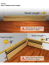
Measuring and custom cutting the track-beam and frame covers
ONE-LEAF DOOR
TWO-LEAF DOOR
WARNING: The two types of beams are supplied in the standard measurements
(001SIPT67 L= 6700 mm e 001SIPT68 L = 6850 mm ).
The track-beams should be cut to fi t your requirements.
To remove the track-beam, start measuring from the side shown in the fi gure.
Overall T length of the fi nished track-beam
fi tted with endcaps:
[T, +] = A X 2 + 26 mm
Overall LT of the track-beam with no
endcaps:
LT = [T, +] - 26 mm
LC = [t, +] - 94 mm
WARNING: the two frame covers
(001SIPC68 and 001SIPC68G) are
supplied in standard size, that is L =
6850 mm. Cut these according to your
requirements.

001SIPT67
45 mm
Ø 8
45 mm
PA
45 mm
Ø 8
001SIPT68
45
45
125250250250
250250250250
45 mm
67 1716
Fig. A
25
55
25
Fig. B
p.
11
11 -
Manual code:
119 P M 9 9
119PM99 ver.
2.0
2.0 07/2011
© CAME Cancelli Automatici S.p.a. - The data and information in this manual may be changed at any time and without obligation on the part of Came Cancelli Automatici S.p.a. to notify said changes.
ENGLISH
WARNING: The fastening frame (001SIPP68) is supplied in the standard measurements of (L
= 6850 mm). You will need to cut it to suit your needs.
To cut the fastening frame
001SIPT68 - After cutting the track-
beam down to size, drill two holes 45
mm from the right edge and drill two
holes 45 mm from the left edge; starting
from the right (see fi gure) continue
drilling holes at distances of 250 mm.
Respect the distribution of drilled holes
as shown in fi g. A .
Note: set up a Ø 25 mm hole for the
electric cables to pass through, in the
most suitable position depending on
the existing cables, see the example in
(fi g.B ). It is up to the installer to choose
the most suitable solution.
001SIPT67 - After cutting the track-beam
down to size, drill two holes 45 mm from
the right edge and drill two holes 45 mm
from the left edge for anchoring to the
wall later.
PA = [T, +] - 100 mm
Perforating the track beam

Ø 8
4
5
7
6
Ø 8
1
2
150
3
00
mm
max
109
mm
Ø 8
45
45
125
250
x n° passi
1
2
3
p.
12
12 - Manual code:
119 P M 9 9
119PM99 ver.
2.0
2.0 07/2011 © CAME Cancelli Automatici S.p.a. - The data and information in this manual may be changed at any time and without obligation on the part of Came Cancelli Automatici S.p.a. to notify said changes.
ENGLISH
Marking the holes
001SIPT67 - Level the track beamn) and mark the spots where to perforate the wall (o).
Drill Ø 8 holes where previously marked, fi t the plugs (p).
001SIPT68 - Level the attaching frame (n) e mark the perforation points on the wall; the fastening frame is already perforated.
Perforate the marked points (Ø 8) (o), insert the plugs and frame using the washers and bolts (p).
Hook the track-beam to the frame to mark a perforation point on the wall (q), remove the beam (r), make a (Ø 8) hole (s) and insert
the plugs (t).

50
mm
LG = LT - 100
LS = LT
2
1
1
25 mm
2
3
p.
13
13 -
Manual code:
119 P M 9 9
119PM99 ver.
2.0
2.0 07/2011
© CAME Cancelli Automatici S.p.a. - The data and information in this manual may be changed at any time and without obligation on the part of Came Cancelli Automatici S.p.a. to notify said changes.
ENGLISH
Seals and dust-brush
Trim seal and dust-brush down to size. Fit
the seal into the top part of the track-beam
(n) and fi t the brush strip into the bottom
part (o).
Fitting the fastening strip for the card and belt return wheel
For easier installation of the gearmotor assembly and card unit, we suggest fi tting
the anchoring bracket as shown in the fi gure (n).
Fit the return wheel about 25 mm towards the
inside of the track-beam (o) and fasten the
hexagonal head bolts (p).

25 mm
2
a
a
p.
14
14 - Manual code:
119 P M 9 9
119PM99 ver.
2.0
2.0 07/2011 © CAME Cancelli Automatici S.p.a. - The data and information in this manual may be changed at any time and without obligation on the part of Came Cancelli Automatici S.p.a. to notify said changes.
ENGLISH
Fitting the gearmotor assembly
Move the gearmotor assembly about 25
mm towards the inside of the track-beam
and tighten the hexagonal-head bolts.
Fitting the mechanical stop
Fit the mechanical stop both left and right
of the track-beam, move them inwards
and slightly tighten the screw.
Fitting the endcaps
Fit both end caps and secure them using the supplied screws.

p.
15
15 -
Manual code:
119 P M 9 9
119PM99 ver.
2.0
2.0 07/2011
© CAME Cancelli Automatici S.p.a. - The data and information in this manual may be changed at any time and without obligation on the part of Came Cancelli Automatici S.p.a. to notify said changes.
ENGLISH
001SIPT68 - Hook up the track-beam to the frame and fasten it to the
wall.
Anchoring the track-beam
001SIPT67 - Fasten the track-beam to the
wall.

V
H
0÷30 mm
10
001MA7370 = L 1000 mm
001MA7470 = L 1500 mm
001MA7570 = L 2000 mm
min. 60 mm
min. 9 mm
Y
20
16
34
80
70
53 17
17
20
ø 4,8
21,5
40
16
001MA7370 = L 1000 mm
001MA7470 = L 1500 mm
001MA7570 = L 2000 mm
001MA7353 = L 1000 mm
001MA7453 = L 1500 mm
001MA7553 = L 2000 mm
LL LL
L anta - 2 mm
L anta
100
18
18
ø 8,5
32
32
101
100
101
min. 300
ø 16
V = Y - 73 mm V = Y - 25 mm
10 V
Y = H + (0 ÷ 30 mm)
± 6
p.
16
16 - Manual code:
119 P M 9 9
119PM99 ver.
2.0
2.0 07/2011 © CAME Cancelli Automatici S.p.a. - The data and information in this manual may be changed at any time and without obligation on the part of Came Cancelli Automatici S.p.a. to notify said changes.
ENGLISH
Track-beam frame
Glass fastening frame
Y = Track-beam anchoring
height
H = Passage height
V = Height of glass
Solution with glass door leaf
with bottom skirting board
Glass door leaf with kick board. Glass door-leaf without kick board.
Hole-drilling quotas for glass and top
cross-beam
Solution with glass
door leaf with bottom
skirting board
Bottom guide-frame
Inner guide sled
Glass door-frame patterns

LL
I
I
I
10
001MA7371 = L 1000 mm
001MA7471 = L 1500 mm
001MA7571 = L 2000 mm
Y
H
20
20
2
40
26,5
± 6
001MA7370 = L 1000 mm
001MA7470 = L 1500 mm
001MA7570 = L 2000 mm
001MA7351 = L 1000 mm
001MA7451 = L 1500 mm
001MA7551 = L 2000 mm
LL
10
10
30
I = Y - 31 mm I = Y - 31 mmI = Y - 51 mm
min. 60 mm
min. 9 mm
0÷30 mm
Y = H + (0 ÷ 30 mm)
p.
17
17 -
Manual code:
119 P M 9 9
119PM99 ver.
2.0
2.0 07/2011
© CAME Cancelli Automatici S.p.a. - The data and information in this manual may be changed at any time and without obligation on the part of Came Cancelli Automatici S.p.a. to notify said changes.
ENGLISH
Framed door patterns
Track-beam frame
Hooking-frame
framed
Bottom
guide-frame
Inner
guide sled
Outer
guide sled
Framed door-leaf without bottom guide-
frame
Framed door leaf with bottom guide-frame Assembling the top guide-frame
Solution with
framed door-leaf
without bottom
guide-frame
Solution with
framed door-leaf
with bottom guide-
frame applied
externally
Solution with
framed door-leaf
with bottom guide-
frame applied
internally
Y = Track-beam anchoring
height
H = Passage height
I = Framed door-leaf height

2
1
2
40 mm
10 mm
40 mm
10 mm
p.
18
18 - Manual code:
119 P M 9 9
119PM99 ver.
2.0
2.0 07/2011 © CAME Cancelli Automatici S.p.a. - The data and information in this manual may be changed at any time and without obligation on the part of Came Cancelli Automatici S.p.a. to notify said changes.
ENGLISH
Fitting the hanging wheels, anti-derailing system and belt clamp for DOUBLE-LEAF siding doors
Assemble the hanger wheels and
fastening strips (supplied with the door
lead top-frame guide). Leave screws loose
(n).
Fit hanger wheels to door-leaf frame (o).
Position the hanging wheels as
shown in the fi gure and tighten
the bolts on the brackets.
Secure the anti-derailing system and belt fastener as shown
in the fi gure.
Left door-leaf
Right door-leaf
Note: the following assembly instructions are for FRAMED DOOR-LEAVES

40 mm
40 mm
2
1
2
p.
19
19 -
Manual code:
119 P M 9 9
119PM99 ver.
2.0
2.0 07/2011
© CAME Cancelli Automatici S.p.a. - The data and information in this manual may be changed at any time and without obligation on the part of Came Cancelli Automatici S.p.a. to notify said changes.
ENGLISH
Fitting the hanging wheels, anti-derailing system and belt clamp for ONE-LEAF sliding doors
Position the hanging wheels as shown
in the fi gure and tighten the bolts on the
brackets.
Secure the anti-derailing system and belt fastener as
shown in the fi gure.
Assemble the hanger wheels and
fastening strips (supplied with the door
lead top-frame guide). Leave screws loose
(n).
Fit hanger wheels to door-leaf frame (o).

2
1
5
1
4
3
OK
2
5
p.
20
20 - Manual code:
119 P M 9 9
119PM99 ver.
2.0
2.0 07/2011 © CAME Cancelli Automatici S.p.a. - The data and information in this manual may be changed at any time and without obligation on the part of Came Cancelli Automatici S.p.a. to notify said changes.
ENGLISH
Fitting the door leaves
After fitting the door leaf, check that it is level
to ensure proper sliding in the guide (n). If the
door is not perfectly level (o), loosen the two
bolts on the hanger-wheels (p), adjust the angle
by turning the eccentric element screw of each
hanger-wheel ( q) (r). Tighten all of the bolts
including the headless one.
Fit leaf to track-beamn).
Warning: to fasten the leaf, lift the anti-derailing system and
tighten the screw (o).
Note: the following assembly instructions are for a DOUBLE-LEAF system; follow the same instructions also for the SINGLE-LEAF.
/