Page is loading ...

Sheet No.
Issue Date: Rev B, June 18, 2020
© Bosch Automotive Service Solutions Inc.
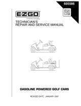
Power Train Lift
Max. Capacity: 2,500 lbs.
1 of 4
Form No. SP04506662
Parts List and
Operating Instructions
for: 1595A
655 EISENHOWER DRIVE
OWATONNA, MN 55060 USA
PHONE: (507) 455-7000
TECH. SERV.: (800) 533-6127
FAX: (800) 955-8329
ORDER ENTRY: (800) 533-6127
FAX: (800) 283-8665
INTERNATIONAL SALES: (507) 455-7223
FAX: (507) 455-7063
5, 29
7
8
9
10
11
19
2
3
4
5
12
14, 15, 16 13
17, 18
28
20
21, 17
25
26, 27
6
12
22, 23
24
1
29
Detail View
Detail View
29

Parts List and Operating Instructions Form No. SP04506662, Sheet 1 of 4, Back
2 522266 1 Riser Frame Weldment
3 522258 1 Riser Frame Weldment
4 523972 1 Table Assembly (see sheet 2 of 4)
7 16696 8 Press-in Grease Fitting
8 522268 8 Nylon Insert Hex Lock Nut
9 522253 4 Frame Tube Weldment
11 SP04506665 1 Base Weldment
12 522254 4 Wheel
13 528723 2 Wood Block
22 525974 2 Keeper Plate
INCLUDED BUT NOT SHOWN
306422 1 Strap Assembly
Frame Hardware Kit 564179
Item Part No.
No. No. Reqd. Description
5 6 Pivot Pin
6 2 Hex Nut, Reversible Lock
24 2 Hex Head Cap Screw
(1-8 UNC x 3.750")
25 4 Washer
29 12 Retaining Ring
Item No.
No. Reqd. Description
Hardware Kit 564182
14 4 Carriage Bolt
15 4 Washer (.474" ID, .926" OD)
16 4 Hex Nut (7/16-14 UNC)
17 2 Lock Nut
18 1 Bolt (.750-10 x 4.00")
21 1 Bolt (.750-10 x 5.00")
23 2 Bushing
26 4 Screw (10-24 x 1/2")
27 2 Glide Strip
INCLUDED BUT NOT SHOWN
(For Pnuematic Version Lifts Only)
4 Hex Head Cap Screw (1/4-20 x .50")
4 Lock Washer (.248" ID)
4 Hex Head Cap Screw
4 Washer (.349" ID, .692 OD")
4 Lock Washer
4 Hex Nut (5/16-18 UNC)
2 Soc. Hd. Cap Screw (3/8-24 x 1/2")
2 Lock Washer
4 Cable Clamp
Item No.
No. Reqd. Description
Caster Kit 579912
19 1 Caster Swivel Lock
20 1 Swivel Caster with Brake
Item No.
No. Reqd. Description
Bolt Pack 579913
Decal Kit SP04506931
28 6 Serrated Flange Bolt (3/8-16 x 3/4")
1 1 Logo/Warning Decal
10 8 Warning Decal
Item No.
No. Reqd. Description
Item No.
No. Reqd. Description

Sheet No.
Issue Date: Rev B, June 18, 2020
© Bosch Automotive Service Solutions Inc.
Parts List and Operating Instructions Form No. SP04506662
2 of 4
Item Part No.
No. No. Reqd. Description
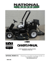
29 523969 1 Table Weldment
33 523950 1 Table Base Weldment
34 523964 1 Threaded Rod
35 523970 2 Threaded Trunnion
43 523966 1 Threaded Rod
INCLUDED BUT NOT SHOWN
523956 1 Table Tilt Weldment
Table Hardware Kit 564183
30 2 Screw, Hex Head
(1"-8 x 1.5" Long, Grade 8)
31 2 Washer
32 2 Reversible Lock Nut
36 4 Thrust Bearing Washer
37 4 Locking Collar
38 2 Bushing
41 2 Set Screw
42 2 Spacer
Item No.
No. Reqd. Description
523972 TABLE ASSEMBLY
29
35
30, 31, 32
33
34
36
37
43
42
38
36
37
41

Parts List and Operating Instructions Form No. SP04506662, Sheet 2 of 4, Back
HYDRAULIC SYSTEM
Item Part No.
No. No. Reqd. Description
44 600021 1 Hydraulic System (Complete)

Sheet No.
Issue Date: Rev B, June 18, 2020
© Bosch Automotive Service Solutions Inc.
Preparation and Set Up
Unpackaging
1. Cut shipping banding from carton and platform.
2. Remove the wood chocks from around the caster wheels.
3. Carefully roll the Power Train Lift off the shipping pallet onto the floor.
Prepare The Air Pump For Operation
A. Pictogram Definitions
B. Cut shipping tie straps from air pump.
C. Air Supply Hook Up
1. Remove the thread protector from the air inlet of the pump. The pump's air inlet is 1/4-18 NPT
internal threads. Select and install the threaded fittings which are compatible with your air supply
fittings. The air supply should be 20 CFM (.57 M³/min.) at 100 PSI (7 BAR) at the pump to obtain
the rated hydraulic pressure. Air pressure should be regulated to between 50 PSI (3.5 BAR) and
140 PSI (9.5 BAR). A pressure of 100 PSI (7 BAR) is the recommended minimum. Secure your
pump fitting to the air supply.
2. It is highly recommended to install an automatic air line oiler to the air supply as close to the pump
as possible. Set the unit to feed approximately one drop of oil per minute into the system. Use SAE
grade oil, 5W to 30W.
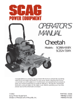
D. Priming The Pump Unit
Under certain circumstances it may be necessary to prime the air pump.
To accomplish this, perform the following procedure:
1. Press the release end of the pedal while holding down
the air intake valve with a flathead screwdriver. The air
intake valve is located directly under the pedal in the area
marked . The valve is depressed simultaneously
with the area of the pedal during priming.
2. Allow the pump to cycle approximately 15 seconds.
3. Remove the screwdriver and press the end of the
pedal once more.
4. If the cylinder extends or pressure builds, the pump has
been successfully primed. If the pump does not respond,
repeat the procedure, jogging the air intake valve while
holding the pedal in the position.
Activating the pump with the pedal end marked with this pictogram,
the flow of fluids is directed out of the reservoir.
Activating the pump with the pedal end marked with this pictogram,
the flow of fluids is directed back to the reservoir.
Air
Intake
Valve
Filler/
Vent
Cap
Air Inlet
(1/4-18 NPT
internal)
3 of 4
Parts List and Operating Instructions Form No. SP04506662

Functional Check of Lift
Without external load applied to the Lift platform, fully raise and lower multiple times to ensure proper function
of the hydraulic system and scissor components.
1. Press the end of the air pump foot pedal marked to raise the Lift platform until it stops at maximum
extension.
2. Press and hold the end of the air pump foot pedal marked to lower the Lift platform until it reaches
a fully collapsed position.
3. Ensure platform raises and lowers only when the air pump foot pedal is actively depressed by the operator.
WARNING: To prevent personal injury and/or equipment damage, if platform moves after air
pump pedal is released, discontinue use and service immediately.
Safety Precautions
WARNING: To prevent personal injury or equipment damage,
• Study, understand, and follow all instructions before operating this device.
• Wear eye protection that meets OSHA and ANSI Z87.1 standards.
• No alterations shall be made to this product
• Before using the Power Train Lift, inspect the unit for leaks, or damaged, loose, or missing
parts. Immediately replace cut, frayed, damaged hoses.
• Only use attachments and/or adapters supplied by the manufacturer.
• Adequately support the vehicle before starting repairs.
• Securely tighten the strap assembly around the component being lifted.
• Do not exceed the rated capacity.
• Do not lift or move a load that has a center of gravity extending beyond the wheels.
Tipping can result in personal injury.
• Do not move the Power Train Lift while the load is raised. Always lower the load completely
before moving or storing the load.
• Carefully and slowly move a load on an incline or around a corner. Tipping can result
in personal injury.
• Use only on a hard, level surface.
• Do not stand under a load that is supported by the Power Train Lift.
• The component must be securely held in place before it is removed from the Power
Train Lift.
Parts List and Operating Instructions Form No. SP04506662, Sheet 3 of 4, Back

Sheet No.
Issue Date: Rev B, June 18, 2020
© Bosch Automotive Service Solutions Inc.
This document contains product parts lists, and information
regarding operation and maintenance. Items listed in the
parts list have been carefully tested and selected by OTC.
Therefore: Use only OTC replacement parts.
Product questions can be directed to the OTC Technical
Service Department at (800) 533-6127.
Get parts at
OTCparts.com
Operating Instructions
Removal
1. Follow the vehicle manufacturer’s recommended service procedure for removal of the component.
2. Position the Power Train Lift under the vehicle.
3. Raise the Power Train Lift to the load.
4. A
djust the wood blocks to fit the assembly, and tighten the nuts to secure the blocks in place.
5. Turn the adjusting screws (items 34 and 43) to align the lift with the component. Raise the lift to the correct
position.
6. Place the strap assembly around the component, and tighten the strap securely to the hook holes.
7. Remove any remaining bolts from the vehicle component.
8. Lower the Power Train Lift and the vehicle component until the Lift is completely collapsed.
9. Move the Lift and load out from under the vehicle.
Installation
1. Position the Power Train Lift under the chassis.
2. Raise the Power Train Lift and turn the adjusting screws to align the component in the correct position.
3. Follow the vehicle manufacturer’s recommended service procedure for installing the component.
Maintenance
Use a good grade lubricant to regularly lubricate the pivot points, the adjusting screws, and the swivel casters.
Parts List and Operating Instructions Form No. SP04506662
4 of 4
/