Honeywell Stratos MS2x20 Series User manual
- Category
- Bar code readers
- Type
- User manual
This manual is also suitable for

MS2320
StratosH
™
Scanner / Diva Scale
Installation and User’s Guide

Disclaimer
Honeywell International Inc. (“HII”) reserves the right to make changes in specifications and other information contained in this
document without prior notice, and the reader should in all cases consult HII to determine whether any such changes have been made.
The information in this publication does not represent a commitment on the part of HII.
HII shall not be liable for technical or editorial errors or omissions contained herein: nor for incidental or consequential damages
resulting from the furnishing, performance, or use of this manual.
This document contains propriety information that is protected by copyright. All rights reserved. No part of this document may be
photocopied, reproduced, or translated into another language without the prior written consent of HII.
© 2006 - 2012 Honeywell International Inc. All rights reserved.
Web Address:
Trademarks
www.honeywellaidc.com
StratosH, MetroSet, and MetroSelect are a trademarks or registered trademarks of Metrologic Instruments, Inc. in the United States
and/or other countries.
Microsoft, Windows, and Windows 95 are trademarks or registered trademarks of Microsoft Corporation.
IBM is a trademark of International Business Machines Corporation.
Other product names mentioned in this manual may be trademarks or registered trademarks of their respective companies and are the
property of their respective owners.
Patents
For patent information, please refer to www.honeywellaidc.com/Patents.

ii
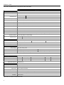
TABLE OF CONTENTS
I
NTRODUCTION
Manual Scope ........................................................................................................................................................................................ 1
Product Overview ................................................................................................................................................................................... 1
Base Kit Components ............................................................................................................................................................................. 2
Optional Accessories .............................................................................................................................................................................. 2
Replacement Parts ................................................................................................................................................................................. 4
General Precautions ............................................................................................................................................................................... 5
MS2320 Scanner/Diva Scale Design Specifications .............................................................................................................................. 6
BASE MODEL CHARACTERISTICS
MS2320 Scanner/Diva Scale .................................................................................................................................................................. 7
Components ....................................................................................................................................................................................... 7
Dimensions ......................................................................................................................................................................................... 8
Connector Panel ................................................................................................................................................................................. 8
Caution and Serial Number Labels ..................................................................................................................................................... 9
INSTALLATION
Quick Installation Outline ...................................................................................................................................................................... 10
Site Requirements ................................................................................................................................................................................ 10
Vertical Clearance ............................................................................................................................................................................ 10
Ventilation and Spacing .................................................................................................................................................................... 10
Service Access ................................................................................................................................................................................. 10
Power Installation ............................................................................................................................................................................. 11
Checkout Counter Layout Consideration .......................................................................................................................................... 11
Unpacking the Unit ............................................................................................................................................................................... 12
MS2320 Package Warning ............................................................................................................................................................... 13
Lifting the Unit by the Handles .......................................................................................................................................................... 13
MS2320 Mounting Diagram (Two Point Support) ............................................................................................................................. 14
MS2320 Mounting Diagram (Three Point Support) .......................................................................................................................... 15
Cable Installation (Interface Specific) ................................................................................................................................................... 16
RS232 .............................................................................................................................................................................................. 16
Full Speed USB ................................................................................................................................................................................ 18
IBM OEM ....................................................................................................................................................................................... 19
Serial Emulation Mode .................................................................................................................................................................. 19
Keyboard Emulation Mode ............................................................................................................................................................ 19
RS485 .............................................................................................................................................................................................. 21

iii
TABLE OF CONTENTS
Cable Installation (Secondary Honeywell Scanner) .............................................................................................................................. 23
EAS Deactivation ................................................................................................................................................................................. 25
SCANNER OPERATION
Scan Zone ............................................................................................................................................................................................ 26
IR Activation Area (IR LED Output) ...................................................................................................................................................... 28
Indicator Descriptions ........................................................................................................................................................................... 29
Audible ............................................................................................................................................................................................. 29
Visual ............................................................................................................................................................................................... 29
Failure .............................................................................................................................................................................................. 30
Diagnostic Indicator Display; Error Codes ........................................................................................................................................ 31
Power Save Modes .............................................................................................................................................................................. 33
Beeper Options and Button Functions .................................................................................................................................................. 34
Beeper Tone and Volume Control .................................................................................................................................................... 34
The Multi-Function Button ................................................................................................................................................................ 34
Startup .................................................................................................................................................................................................. 35
Power-Up Test Mode ........................................................................................................................................................................... 35
Configuration Mode .............................................................................................................................................................................. 35
SCALE OPERATION
Scale Zeroing ....................................................................................................................................................................................... 36
Calibration ............................................................................................................................................................................................ 37
Tools Required ................................................................................................................................................................................. 37
Scale Calibration Methods ................................................................................................................................................................ 37
Priming the Scale for Calibration (lbs. & kg) ..................................................................................................................................... 38
Scale Calibration Procedure (lbs. & kg) with Remote Display .......................................................................................................... 39
Bar Code Calibration Procedure without Remote Display ................................................................................................................ 42
Calibration Verification ......................................................................................................................................................................... 46
U.S. Pounds (lbs.) ............................................................................................................................................................................ 46
Kilograms (kg) .................................................................................................................................................................................. 47
Security Seal Installation ...................................................................................................................................................................... 48
Pressure Sensitive Security Seal ..................................................................................................................................................... 48
Wire Security Seal (Conversion Kit 46-00359) ................................................................................................................................. 49
MAINTENANCE
Platter / Horizontal Scan Window Replacement ................................................................................................................................... 50
Vertical Scan Window Replacement .................................................................................................................................................... 51
Daily Maintenance ................................................................................................................................................................................ 51

iv
TABLE OF CONTENTS
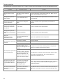
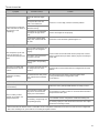
TROUBLESHOOTING
Troubleshooting Symptom / Solution Chart .......................................................................................................................................... 52
SCANNER AND CABLE TERMINATIONS
Scanner Pinout Connections ................................................................................................................................................................ 54
Cable Connector Configurations .......................................................................................................................................................... 56
REGULATORY COMPLIANCE
Safety ................................................................................................................................................................................................... 58
EMC ..................................................................................................................................................................................................... 59
Weights & Measures ............................................................................................................................................................................ 60
LIMITED WARRANTY .................................................................................................................................................................................... 61
INDEX......................................................................................................................................................................................................... 62
CUSTOMER SUPPORT
Technical Assistance ............................................................................................................................................................................ 64
Product Service and Repair .................................................................................................................................................................. 64

v

1
INTRODUCTION
MANUAL SCOPE
This guide provides information on the installation, setup and operation of Honeywell’s StratosH™ MS2320 scanner/Diva scale unit. It
is designed to be used in conjunction with MetroSelect™ Configuration Guide (
PN 00-02407x) and the MS2x20 Stratos Series
Scanner/Diva Scale Configuration Addendum (PN 00-02272x).
Product manuals are also available for download in Adobe
®
Acrobat
®
file format at www.honeywellaidc.com.
PRODUCT OVERVIEW
The StratosH MS2320 is designed to meet the demanding needs of high volume supermarket and point-of-sale applications. With
advanced features like 6-sided, 360° scanning, 5840 scans per second, a comprehensive scan zone and advanced decoding software,
this high performance in-counter scanner/scale model guarantees fast customer checkouts with minimal operator fatigue and stress.
The MS2320 scanner/scale is equipped with a multitude of standard features including:
• StratosSCAN – 6-sided, 360° scanning that minimizes product orientation
• StratosSPHERE – Decoding software that reads poor quality and damaged bar codes
• StratosSYNC – Horizontal and vertical scanning zones operate independently from one another
• GS1 DataBar Decoding – Decodes GS1 DataBar, GS1 DataBar Limited and GS1 DataBar Expanded symbologies
• Flash ROM – Upgrade latest software enhancements on site
• Powered Aux Port – Connect hand-held scanner for large or bulky items
• Integrated Scale – Factory integrated Mettler Toledo Diva scale
• Loud Speaker – Three volume/seven tone settings can be heard in all environments
• Easy Configuration – Windows
®
• Fully Automatic – “No touch” infrared wake up from power save modes
based utility or simple bar code setup
• EAS Deactivation – Electronic Article Surveillance (EAS) equipped (EAS cable is an optional purchase)
• Field Replaceable Vertical Window – Quickly remove vertical window for cleaning or replacement
• StratosSCOPE – Visual diagnostic indicator for easy to read feedback on scanner condition
• StratosSWAP – Modular optics engine technology – small, pre-aligned, field replaceable modules
• StratosSCHOOL – Operator training software

2
INTRODUCTION
B
ASE KIT COMPONENTS
BASE KIT COMPONENTS
Part # Description
MS2320-xxKz StratosH Scanner / Diva Scale
xx
14 RS232 Interface
21 RS232 / Full Speed USB / RS485 Interfaces
z
D Diamonex Horizontal Window
S Sapphire Horizontal Window
00-02407x MetroSelect Configuration Guide
00-02272x MS2x20 Stratos Series Scanner/Diva Scale Configuration Addendum
00-02271x MS2320 StratosH Scanner/Diva Scale Installation and User’s Guide
Guides also available for download at www.honeywellaidc.com.
Other items may be ordered for the specific protocol being used. To order additional items, contact the dealer, distributor or customer service
department.
O
PTIONAL ACCESSORIES
OPTIONAL ACCESSORIES
Part # Description
57-57000x-N-3 RS232 Interface Cable, Straight Cord
57-57004x-N-3 RS485
57-57200x-N-3
Port 9 Cable, Straight Cord
USB Full Speed Communication Cable, Straight Cord, Locking 12V Plus-Power
™
57-57006x-N-3
Type A
USB Full Speed Communication Cable, Straight Cord, Non-Locking Type A
57-57099x-3 LSO RS232 PowerLink AUX Cable with built in power jack, Straight Cord
57-57099x-3-12
RS232 AUX, Straight Cord, 3.7 m (12') (for 95xx, 5145 and 7580 scanners)
CBL-420-300-C00 RS232 AUX, Coiled Cord (for 1200, 1300 and 1900 Series scanners)
57-57000x-N-3 Dual Interface Cable, Straight Cord
52-52511x
24" EAS Cable
52-52556x Checkpoint EAS Cable, Straight Cord, 1.8 m (6')
Applicable for IBM
®
Host applications.

3
INTRODUCTION
OPTIONAL ACCESSORIES
Part # Description
AC to DC Power Transformer - Regulated
Output: +5V @ 4A +12V @ 1.5A
46-46812 120V United States and Canada
46-46813 220V – 240V Continental European
46-46814 220V – 240V United Kingdom
46-46817 220V – 240V China
46-46928 220V – 240V Australia
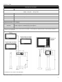
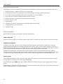
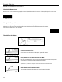
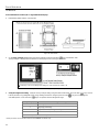
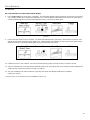
Optional Remote Scale Display
46-00375 Remote Single Line Scale Display (lb.) (See Figure 1)
46-00376 Remote Single Line Scale Display (kg.) (See Figure 1)
46-00377 Remote Four Line Scale Display (kg.) (See Figure 2)
Other Four Line Scale Display currency overlay stickers are available. To order additional or replacement items, contact the dealer, distributor or
customer service department.
Specifications are subject to change without notice.
Figure 1
Figure 2
* All dimensions are shown in mm (millimeters).

4
INTRODUCTION
REPLACEMENT PARTS
REPLACEMENT PARTS
Part # Description
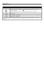
Caution
Window types (Diamonex and Sapphire) are
not
interchangeable due to laser safety and/or scanner
performance differences.
To change window type, the scanner must be returned to the manufacturer for reconfiguration.
46-46889 Vertical Window
46-46806 Diamonex Platter – Full (Long) Size
46-46808 Sapphire Platter – Full (Long) Size
Other items may be ordered for the specific protocol being used. To order additional items, contact the dealer, distributor or customer service
department.

5
INTRODUCTION
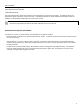
GENERAL PRECAUTIONS
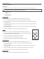
The following list includes general precautions to remember when handling the StratosH.
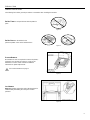
DO NOT TURN the unit upside down with the platter in
place.
DO NOT PRESS on the window in the
placement platter or the vertical window frame.
PLATTER REMOVAL
No hardware or tools are required to remove the platter /
horizontal scan window (see Figure 5). Refer to the
Maintenance section of this manual for additional
information on platter replacement.
See caution statement on page 4.
LIFT HANDLES
REST both thumbs against the vertical window frame for
added stability when lifting the unit by the handles
provided.
Figure 6
Figure 4
Figure 3
Figure 5

6
INTRODUCTION
MS2320 SCANNER/DIVA SCALE DESIGN SPECIFICATIONS
Design Specifications
Operational
Light Source: VLD 650 nm
Peak Laser Power: <2.2 mW
Embedded Laser:
Max Optical Power: 10 mW
Wavelength: 650 nm
Horizontal Depth of Field: 0 mm - 152 mm (0"- 6") for 0.33 mm (13 mil) Bar Code
Vertical Depth of Field: 0 mm - 216 mm (0"- 8.5"”) for 0.33 mm (13 mil) Bar Code
Scan Speed: 5840 Scan Lines per Second
No. of Scan Lines: 66 (38 Horizontal / 28 Vertical)
Motor Speed: 4800 / 6000 RPM (Horizontal / Vertical )
Min Bar Width: 0.152 mm (6.0 mil)
Decode Capability: All Standard 1-D Bar Codes, GS1 DataBar, GS1 DataBar Expanded, and GS1 DataBar Limited Bar Codes
System Interfaces: RS232, Aux RS232, RS485 and USB
Print Contrast: 35% Minimum Reflectance Difference
No. Characters Read: Up to 80 data characters. Maximum number will vary based on symbology and density.
Beeper Operation: 7 Tones or No Beep; 3 Volume Settings
Indicators (LED):
Blue Laser ON, Ready to Scan
White Good Read, Decoding
Mechanical
L x W x H: 508 mm (20") Length 290 mm (11.4") Width 181 mm (7.1") Tower Height
Depth (Below Counter): 100 mm (3.9")
Weight (with Platter): 11.34 kg (24.95 lbs.)
Electrical
Voltage Supply: 4A @ +5V / 1.5A @ +12V
Power: Operating, 14.25 Watts Standby, 3.25 Watts
Current: Operating, 1A @ 5V / 0.75A @ 12V Standby, 0.44 A @ 5V / 0.08A @ 12V
DC Transformers: Class II; 5.2VDC @ 3.8A; 12VDC @ 1.5A
For Regulatory Compliance Information, refer to pages 58 - 60.
Scale Capacities
Capacity: kg unit 6.0 / 15.0 kg lb. unit 15.0 / 30.0 lb.
Minimum Increments: kg unit 0.002 / 0.005 kg lb. unit 0.005 / 0.01 lb.
Maximum Static Weight: kg unit 75.0 kg lb. unit 150.0 lb.
Adjustments Required: Calibration Only
Environmental
Operating Temperature: 0°C to 40°C (32°F to 104°F)
IP Rating: IP 55
Light Levels: 4842 Lux (450 foot-candles)
Storage Temperature: -40°C to 60°C (-40°F to 140°F)
Humidity: 5% to 95% Relative Humidity, Non-Condensing
Contaminants: Sealed to resist airborne particulate contaminants.
Ventilation: None Required
Specifications are subject to change without notice.

7
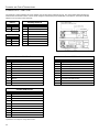
BASE MODEL CHARACTERISTICS
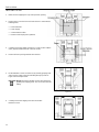
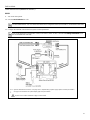
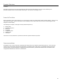
MS2320 Scanner/Diva Scale
Components
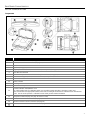
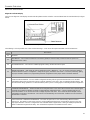
Figure 7. MS2320 Components
ITEM NO. DESCRIPTION OF ITEM
1 Blue and White LED Indicators (see page 29)
2 Volume/Tone Multi-Function Button (see page 34)
3 Scale Zero Button
4 Speaker (see page 29)
5 High Impact Window Frame / Vertical Window (Laser Aperture) (see page 4)
6 Flow Direction Indicators
7 Platter with Finger Recess, Stainless Steel Option Not Shown (see page 4)
8 Diamonex or Sapphire (shown) Horizontal Window (Laser Aperture)
9 Scale Side Guards
10 Debris Channel
11 Leveling Bubble
12 Handles for Lifting Unit
13
Sealed Calibration Switch/Button Cover
On a fully installed unit, the calibration switch cover should be sealed with either a lead wire or paper seal.
The seal indicates if the appropriate Federal, State and Local Weights and Measures authorities have calibrated the
scale. See the Scale Operation: Calibration section of this guide for further information.
14 Diagnostic Indicator Display (see page 31 for Error Codes)
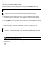
15 Power, Scale and EAS Connectors (see page 8)
16 Interface and Aux Scanner Connectors (see page 8)
Scanner/Scale label information can be found on page 9.

8
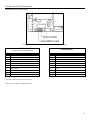
BASE MODEL CHARACTERISTICS
MS2320 Scanner/Diva Scale
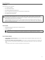
Dimensions
Figure 8. MS2320 Dimensions
Connector Panel
Figure 9. MS2320 Connector Panel
Specifications are subject to change without notice.

9
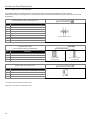
BASE MODEL CHARACTERISTICS
MS2320 Scanner/Diva Scale
Caution and Serial Number Labels
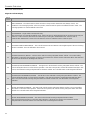
Figure 10. MS2320 Label Locations (Top) and Examples (Bottom)
Caution: To maintain compliance with applicable standards, all circuits connected to the scanner must meet the requirements for SELV (Safety
Extra Low Voltage) according to EN/IEC 60950-1.
To maintain compliance with standard CSA C22.2 No. 60950-1/UL 60950-1 and norm EN/IEC 60950-1, the power source should meet
applicable performance requirements for a limited power source.

10
INSTALLATION
Q
UICK INSTALLATION OUTLINE
The following is a quick preview of the steps required for first time installations. Each item is discussed in detail later in this section.
• Determine clearance, ventilation and service access requirements.
• Determine checkout counter layout taking into account package flow, cable routing and power requirements.
• Choose the mounting option which provides the best cable/power access and unit stability.
• Unpack the unit and remove the shipping hardware from the scale arms.
• Make the appropriate countertop cutouts and install all support brackets.
• Place the unit in the counter.
• Install the platter.
• Follow the steps under the correct interface to connect the cables and power supply.
• Configure the unit for the correct interface.
• Calibrate the scale.
SITE REQUIREMENTS
Before installing the StratosH scanner, please consider the following items.
Vertical Clearance
A minimum clearance height of 7.00" from the checkout counter surface is needed for the vertical 'hood' on all of the scanner models.
Ventilation and Spacing
All StratosH models have a die-cast housing to dissipate heat allowing the unit to operate without a ventilation fan. Honeywell
recommends that the temperature surrounding the unit does not exceed 40°C (104°F). There should be adequate convection and
minimal heat producing equipment in close proximity of the unit. A cooling fan with a filter is recommended if there will be a conveyor
motor or other heat producing equipment close to the unit that will create a high temperature environment.
Adequate spacing between the unit and the checkout counter opening is required for proper operation of the scale. When the
scanner/scale model is mounted properly, the scale platter should be able to move up and down freely without hitting the edges of the
checkout counter cutout. Refer to Installing the Unit in the Counter for detailed cutout dimensions and mounting instructions.
Service Access
When routing and installing the cable(s) and power supply, make sure to leave access so that these components may be swapped
easily without the need to remove the unit from the checkout counter.
When changing the StratosSWAP optics engine modules, Honeywell recommends removing the unit completely from the checkout
counter.
When calibrating or zeroing the scale, do not remove the unit from the checkout counter. Refer to the Scale Operation Section of this
guide for detailed instructions on zeroing and calibration.

11
INSTALLATION
Q
UICK INSTALLATION OUTLINE
POWER INSTALLATION
The Power Supply (AC/DC) should be connected to an AC Outlet that is free of electrical noise (clean). A qualified electrician can
determine the amount of electrical noise on the AC line. See additional information on power installation and restrictions under the
Installation: Cable Installation (Interface Specific) section of this manual.
Honeywell recommends using a switched AC outlet. The switch should be located on the operator’s side of the checkout
counter in close proximity to the StratosH to facilitate calibration and service of the unit.
Checkout Counter Layout Considerations
When placing a scanner in a checkout counter, the following factors should be considered.
• Items should flow at a distance to the operator that maximizes comfort. The operator should not need to stretch or strain to reach
for and scan packages.
• The StratosH can scan a bar code on six sides of a package. The packages should flow into the scan area that provides the
maximum reading performance. No lifting or orientation of the items is necessary. A properly placed item diverter can maximize
the flow of packages.
• In what direction are the packages flowing? Most checkout counters are designed for left-handed takeaway. If the operator is
facing the vertical window of the scanner, packages flow from the operator's right to left. The packages are in queue on the
conveyor to the right and the bagging is to the left.

12
INSTALLATION
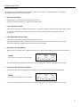
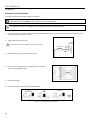
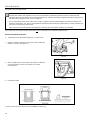
UNPACKING THE UNIT
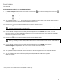
1. Make sure the shipping box is top-side up before opening.
2. Remove the accessories box and check the box’s content for the
following items:
• Product Manuals
• Power Supply
• Communication Cables
• Remote Scale Display Pole (Optional)
3. Carefully remove the platter and store it in a safe location until the
unit is properly installed into the checkout counter.
4. Remove all loose packing materials from the box.
5. Lift the MS2320 scanner out of the box by carefully grasping both
sides near the center of the unit and lifting directly up. Refer to
Figure 13 for hand placement.
Important! Do not remove the MS2320 scanner from the box by
grabbing the shipping foam. This can result in the unit
falling!
6. Carefully remove the shipping foam from around the
MS2320 scanner.
Figure 11
Figure 12
Figure 13
Figure 14

13
INSTALLATION
UNPACKING THE UNIT
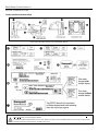
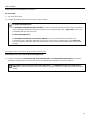
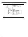
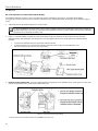
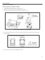
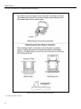
MS2320 Package Warning
There is a protective film located on the topside platter surface, vertical scan windows outer surface, and the horizontal scan
windows top surface. This film
must
be removed prior to performing any scanner operation (see Figure 15).
All foam wedges securing the scale arms during shipping
must
be removed or the scale will not function (see Figure 15)!
Do not discard these instructions and shipping foam wedges! If the unit is going to be reshipped at any time this foam
must
be reinstalled prevent damage to the scale arms during shipping.
There is a protective sheet layered behind the Vertical Scan Window which must be removed or the MS2320 scanning ability will be
greatly reduced (see Figure 16).
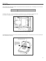
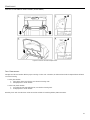
Lifting the Unit by the Handles
There are two handles located under the removable platter near the
base of the vertical window. These handles are provided to assist in
installation when placing the unit in the checkout counter cutout.
To decrease the risk of dropping the unit during installation, rest
both thumbs against the vertical window frame for added stability
when lifting the unit by the handles. The unit will tilt forward when
lifted by the handles if it is not stabilized making installation in the
countertop cutout difficult.
Figure 17. Handles for Lifting
Figure 15. Removal of Protective Film and Scale Shipping Foam
Figure 16. Removal of Vertical Scan Window Protective Sheet

14
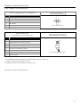
INSTALLATION
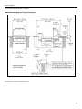
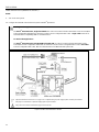
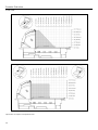
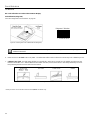
INSTALLING THE UNIT IN THE COUNTER
MS2320 Mounting Diagram (Two Point Support)
Figure 18. MS2320 Mounting Diagram, Two Point Support
Specifications are subject to change without notice.
Page is loading ...
Page is loading ...
Page is loading ...
Page is loading ...
Page is loading ...
Page is loading ...
Page is loading ...
Page is loading ...
Page is loading ...
Page is loading ...
Page is loading ...
Page is loading ...
Page is loading ...
Page is loading ...
Page is loading ...
Page is loading ...
Page is loading ...
Page is loading ...
Page is loading ...
Page is loading ...
Page is loading ...
Page is loading ...
Page is loading ...
Page is loading ...
Page is loading ...
Page is loading ...
Page is loading ...
Page is loading ...
Page is loading ...
Page is loading ...
Page is loading ...
Page is loading ...
Page is loading ...
Page is loading ...
Page is loading ...
Page is loading ...
Page is loading ...
Page is loading ...
Page is loading ...
Page is loading ...
Page is loading ...
Page is loading ...
Page is loading ...
Page is loading ...
Page is loading ...
Page is loading ...
Page is loading ...
Page is loading ...
Page is loading ...
Page is loading ...
Page is loading ...
Page is loading ...
-
 1
1
-
 2
2
-
 3
3
-
 4
4
-
 5
5
-
 6
6
-
 7
7
-
 8
8
-
 9
9
-
 10
10
-
 11
11
-
 12
12
-
 13
13
-
 14
14
-
 15
15
-
 16
16
-
 17
17
-
 18
18
-
 19
19
-
 20
20
-
 21
21
-
 22
22
-
 23
23
-
 24
24
-
 25
25
-
 26
26
-
 27
27
-
 28
28
-
 29
29
-
 30
30
-
 31
31
-
 32
32
-
 33
33
-
 34
34
-
 35
35
-
 36
36
-
 37
37
-
 38
38
-
 39
39
-
 40
40
-
 41
41
-
 42
42
-
 43
43
-
 44
44
-
 45
45
-
 46
46
-
 47
47
-
 48
48
-
 49
49
-
 50
50
-
 51
51
-
 52
52
-
 53
53
-
 54
54
-
 55
55
-
 56
56
-
 57
57
-
 58
58
-
 59
59
-
 60
60
-
 61
61
-
 62
62
-
 63
63
-
 64
64
-
 65
65
-
 66
66
-
 67
67
-
 68
68
-
 69
69
-
 70
70
-
 71
71
-
 72
72


Honeywell Stratos MS2x20 Series User manual
- Category
- Bar code readers
- Type
- User manual
- This manual is also suitable for
Ask a question and I''ll find the answer in the document
Finding information in a document is now easier with AI
Related papers
-
Honeywell 1900 User manual
-
Honeywell 3310g User manual
-
-
-
-
Honeywell Hyperion 1300g User manual
-
Honeywell Voyager XP 1472g Series User guide
-
Honeywell 4600g User manual
-
Honeywell MK2430 Stratos User guide
-
Other documents
-
Detecto SlimPRO Calibration Operating instructions
-
Poly Planar WC3 Template
-
Metrologic StratosH MS2320 Installation and User Manual
-
-
-
Metrologic Instruments MS2322 User manual
-
-
Datalogic MAGELLAN 8300 Owner's manual
-
-
Futech Quattro Owner's manual