Page is loading ...


Printed: 31.07.2017 | Doc-Nr: PUB / 5260701 / 000 / 01

English 1
1 Information about the documentation
1.1 Explanation of signs used
1.1.1 Warnings
Warnings alert persons to hazards that occur when handling or using the product. The following signal words
are used in combination with a symbol:
DANGER! Draws attention to imminent danger that will lead to serious personal injury or fatality.
WARNING! Draws attention to a potential hazard that could lead to serious personal injury or
fatality.
CAUTION! Draws attention to a potentially dangerous situation that could lead to slight personal
injury or damage to the equipment or other property.
1.1.2 Symbols
The following symbols are used:
Read the operating instructions before use.
Instructions for use and other useful information
1.1.3 Illustrations
The illustrations in these operating instructions are intended to convey a basic understanding and may differ
from the actual version of the product:
These numbers refer to the corresponding illustrations found at the beginning of these operating
instructions.
The numbering in the illustrations reflects the order of the work steps in the illustration and may
deviate from the numbering of work steps in the text.
Item reference numbers are used in the overview illustration. In the product overview section, the
numbers shown in the legend relate to these item reference numbers.
1.2 On the product
Laser information
Laser Class 2 based on the IEC60825-1 / EN60825-1:2007 standard in com-
pliance with CFR 21 § 1040 (Laser Notice 50).
Do not stare into beam.
1.3 About this documentation
▶ Read these operating instructions before the product is used or operated for the first time. This is a
prerequisite for safe, trouble-free handling and use of the product.
▶ Observe the safety instructions and warnings printed in this documentation and on the tool.
▶ Always keep the operating instructions with the tool and make sure that the operating instructions are
with the tool when it is given to other persons.
We reserve the right to make changes. Errors excepted.
1.4 Product information
Hilti products are designed for professional use and may be operated, serviced and maintained only by
trained, authorized personnel. This personnel must be informed of any particular hazards that may be
encountered. The product and its ancillary equipment may present hazards when used incorrectly by
untrained personnel or when used not as directed.
The type designation and serial number are printed on the type identification plate.
Printed: 31.07.2017 | Doc-Nr: PUB / 5260701 / 000 / 01

2 English
▶ Write down the serial number in the table below. You will be required to state the product details when
contacting Hilti Service or your local Hilti organization to enquire about the product.
Product information
Rotating laser PR 2-HS A12
Generation 02
Serial no.
2 Safety
2.1 Safety instructions
2.1.1 Basic information concerning safety
Read all safety instructions and other instructions. Failure to observe the safety instructions and other
instructions may result in electric shock, fire and/or serious injury.
Retain all safety precautions and instructions for future reference. The term “electric tool” used in the
safety instructions refers to your mains-operated (corded) electric tool or battery-operated (cordless) electric
tool.
2.1.2 General safety instructions
▶ Stay alert, watch what you are doing and use common sense when operating an electric tool. Do
not use an electric tool while you are tired or under the influence of drugs, alcohol or medication.
A moment of inattention while operating the electric tool may result in serious personal injury.
▶ Do not render safety devices ineffective and do not remove information and warning notices.
▶ Keep laser tools out of reach of children.
▶ Laser radiation in excess of Class 2 may be emitted if the tool is opened without following the correct
procedures. Have the tool repaired only by Hilti Service.
▶ Laser beams should be projected well above or well below eye height.
▶ Take the influences of the surrounding area into account. Do not use the tool where there is a risk
of fire or explosion.
▶ Statement in accordance with FCC §15.21: Changes or modifications not expressly approved by Hilti
may restrict the user’s authorization to operate the equipment.
▶ You must check the accuracy of the tool after it has been dropped or subjected to other mechanical
stresses.
▶ When the tool is brought into a warm environment from very cold conditions, or vice-versa, allow
it to become acclimatized before use.
▶ Make sure that the tool is mounted securely when adapters or accessories are used.
▶ Keep the laser exit aperture clean to avoid measurement errors.
▶ Although the tool is designed for the tough conditions of jobsite use, as with other optical and
electronic instruments (e.g. binoculars, spectacles, cameras) it should be treated with care.
▶ Although the tool is protected to prevent entry of dampness, it should be wiped dry each time
before being put away in its transport container.
▶ Check the tool before using it for important measuring work.
▶ Check the accuracy of the measurements several times during use of the tool.
▶ Ensure that the workplace is well lit.
▶ Do not expose the laser to rain or wet conditions.
▶ Avoid touching the contacts.
▶ Maintain the tool carefully. Check for misalignment or binding of moving parts, breakage of parts
and any other condition that may affect the tool’s operation. Have damaged parts repaired before
using the tool. Many accidents are caused by poorly maintained tools.
2.1.3 Proper preparation of the working area
▶ Secure the area in which you will be taking measurements. Make sure that the laser beam is not
directed toward other persons or toward yourself while setting up the PR 2-HS A12.
▶ Avoid unfavorable body positions when working from ladders. Make sure you work from a safe
stance and stay in balance at all times.
▶ Readings taken in the vicinity of reflective objects or surfaces, through panes of glass or similar materials
may produce incorrect results.
Printed: 31.07.2017 | Doc-Nr: PUB / 5260701 / 000 / 01

English 3
▶ Ensure that the tool is set up on a stable, level surface (not subject to vibration).
▶ Use the tool only within its specified limits.
▶ Use the tool and its accessories etc. in accordance with these instructions and in the manner
intended for the particular type of tool. Take the working conditions and the task to be performed
into account. Use of tools for applications different from those intended could result in a hazardous
situation.
▶ Use of the telescopic staff in the vicinity of overhead high voltage cables is not permissible.
2.1.4 Electromagnetic compatibility
Although the tool complies with the strict requirements of the applicable directives, Hilti cannot exclude the
following possibilities:
• The tool may be negatively affected by powerful electromagnetic radiation, possibly leading to incorrect
operation.
In these cases, or if you are otherwise unsure, confirmatory measurements should be made by other
means.
• The tool may cause interference to other devices (e.g. aircraft navigation equipment).
Only for Korea:
This device is suitable for the electromagnetic radiation encountered in residential environments (Class B). It
is intended mainly for use in residential environments but may also be used in other environments.
2.1.5 Laser classification for Class 2 laser products
The tool complies with laser Class 2 as per IEC60825-1:2007 / EN60825-1:2007. This tool may be used
without need for further protective measures.
CAUTION
Risk of injury! Do not direct the laser beam toward persons.
▶ Never look directly into the source of the laser beam. In the event of direct eye contact, close your
eyes and move your head out of the path of the laser beam.
2.1.6 Careful use of battery-powered tools
▶ Do not expose batteries to high temperatures, the direct heat of the sun, and keep them away
from fire. There is a risk of explosion.
▶ Do not disassemble, squash or incinerate batteries and do not subject them to temperatures over
80°C (176°F). This presents a risk of fire, explosion or injury through contact with caustic substances.
▶ Do not subject the battery to hard mechanical impacts and do not throw the battery.
▶ Batteries must be kept out of reach of children.
▶ Avoid ingress of moisture. Ingress of moisture may cause a short circuit, resulting in burning injuries or
fire.
▶ Under abusive conditions, liquid may leak from the battery. Avoid contact with the liquid. If contact
accidentally occurs, flush with water. If the liquid contacts the eyes, also seek medical attention.
Liquid leaking from the battery may cause irritation or burns.
▶ Use only batteries of the type approved for use with the applicable tool. Use of other batteries or
use of the batteries for purposes for which they are not intended presents a risk of fire and explosion.
▶ Store the battery in a cool and dry place. Never store the battery where it is exposed to direct sunlight or
sources of heat, e.g. on heaters / radiators or behind glass.
▶ When not in use, keep the battery and the charger away from paper clips, coins, keys, nails,
screws or other small metal objects that could cause a short circuit at the battery terminals or the
charging contacts. Short-circuiting the contacts on a battery or charger may cause burning injuries or
start a fire.
▶ Do not charge or continue to use damaged batteries (e.g. batteries with cracks, broken parts, bent
or pushed-in and/or pulled-out contacts).
▶ Recharge only with the charger specified by the manufacturer. A charger that is suitable for a certain
type of battery may present a risk of fire when used with other types of battery.
▶ Observe the special guidelines applicable to the transport, storage and use of Li-ion batteries.
▶ The battery must be insulated or removed from the tool before the tool is shipped or sent by mail.
Leaking batteries may damage the tool.
Printed: 31.07.2017 | Doc-Nr: PUB / 5260701 / 000 / 01

4 English
▶ If the battery gets noticeably hot when not in use, this may indicate that the battery or the tool / battery
system is faulty. In this case, place the tool in a non-flammable location, well away from flammable
materials, where it can be kept under observation and allowed to cool down.
3 Description
3.1 Overview of the product
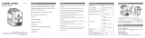
3.1.1 PR 2-HS A12 rotating laser
@
Laser beam (plane of rotation)
;
Rotary head
=
Grip
%
Battery release button
&
Liion battery
(
Battery charge status display
)
Control panel
+
Base plate with 5/8" thread
Printed: 31.07.2017 | Doc-Nr: PUB / 5260701 / 000 / 01

English 5
3.1.2 PR 2-HS A12 control panel
@
On/off button
;
LED: Auto-leveling
=
Button and LED: Shock warning deactiva-
tion
%
Button and LED: Manual inclined plane
mode
&
Battery charge state LEDs
3.1.3 PRA 20 laser receiver control panel
@
On/off button
;
Volume button
=
Units key
%
Receiving area
&
Marking notch
(
Display
Printed: 31.07.2017 | Doc-Nr: PUB / 5260701 / 000 / 01

6 English
3.1.4 PRA 20 laser receiver display
@
Indicator showing distance from laser plane
;
Volume indicator
=
Rotating laser low battery indicator
%
Battery status
&
Indicator showing position of receiver
relative to height of laser plane
(
Display
)
Marking notch
+
Receiving area
3.1.5 Intended use
The product described is a rotating laser with a visible rotating laser beam. It can be operated by one person.
The tool is designed to be used for determining, transferring and checking references in the horizontal and
inclined planes. Examples of uses are transferring datums and heights.
▶ Use only the Hilti B 12⁄2.6 Li-Ion battery for this product.
▶ Use only the Hilti C 4⁄1250 charger for this product.
3.1.6 Features
The rotating laser can be used horizontally and for inclined planes.
The tool is equipped with the following operating status indicators: auto-leveling LED, inclination angle LED
and shock warning LED.
Auto-leveling
Auto-leveling is carried out by two built-in servo motors after switching on. LEDs indicate the current
operating status. Auto-leveling is active within the ±5° range relative to the horizontal plane and can be
deactivated by pressing the button. The tool can be set up directly on the ground or floor, on a tripod, or
with the aid of suitable mounting brackets.
Inclination angle
Alternatively, in inclined plane mode, the slope adapter can be adjusted manually to achieve slopes of up to
60%. Auto-leveling is not active.
Automatic cut-out
The tool switches off automatically if it is unable to level itself, because the laser:
• is inclined at more than 5° relative to the horizontal plane.
• is blocked mechanically.
• has been knocked off level by an impact or vibration.
When the tool has switched itself off, rotation stops and all LEDs blink.
Shock warning
If the laser is knocked off level during operation, the built-in shock warning function switches the tool to
warning mode. The shock warning function becomes active only two minutes after completion of auto-
leveling. If a button on the control panel is pressed within this two-minute period it will again take a further
two minutes until shock warning function becomes active. If the laser is in warning mode:
• all LEDs blink.
• the laser stops rotating.
• the laser beam switches off.
Printed: 31.07.2017 | Doc-Nr: PUB / 5260701 / 000 / 01

English 7
The shock warning function can be switched off by pressing the button if the ground or floor is not free
from vibration or when you are working in inclined plane mode.
Laser receiver
Hilti laser receivers can be used to detect and indicate the laser beam at great distances.
3.1.7 LED indicators
The rotating laser is equipped with an LED display.
Status Meaning
All LEDs blink • The tool has been bumped, knocked off level or
is subject to some other error.
The auto-leveling LED blinks green • The tool is in the leveling phase.
The auto-leveling LED lights green constantly • The tool has leveled itself / is operating normally.
The shock warning LED lights orange constantly • Shock warning mode is deactivated.
The inclination LED lights orange constantly • Inclined plane mode is active.
3.1.8 Li-ion battery charge state display
The Li-ion battery features a state of charge display.
Status Meaning
4 LEDs light. • Charge status: 75 % to 100 %
3 LEDs light. • Charge status: 50 % to 75 %
2 LEDs light. • Charge status: 25 % to 50 %
1 LED lights. • Charge status: 10 % to 25 %
1 LED blinks. • Charge status: < 10 %
Note
When the tool is in operation, the battery charge status is indicated in the display on the tool.
When not in operation, battery charge state can be indicated by lightly pressing the release button.
During charging, charge state is indicated by the LEDs on the battery (please refer to the operating
instructions for the charger).
3.1.9 Items supplied
PR 2-HS A12 rotating laser, PRA 20 (02) laser receiver, 2 batteries (AA cells), PRA 83 laser receiver holder,
2 manufacturer’s certificates, operating instructions.
You can find other system products approved for your product at your local Hilti Center or online at:
www.hilti.com.
4 Technical data
4.1 Technical data for the rotating laser
Receiving range (diameter) PRA 20 (02)
2 m …600 m
Accuracy at 10 m (under standard ambient conditions in
accordance with MILSTD810G)
±0.5 mm
Laser class
Visible, Laser Class 2,
620-690 nm/Po<4.85 mW ≥ 300 ⁄min;
EN 60825-1:2007; IEC 60825-1:2007
Speed of rotation
300 /min
Self-leveling range
±5°
Operating temperature
−20 ℃ …50 ℃
Storage temperature
−25 ℃ …60 ℃
Weight (including B12/2.6 battery)
2.44 kg
Drop test height (under standard ambient conditions in
accordance with MILSTD810G)
1.5 m
Printed: 31.07.2017 | Doc-Nr: PUB / 5260701 / 000 / 01

8 English
Tripod thread
5/8 in
Protection class in accordance with IEC 60529 (except
battery and battery compartment)
IP66
4.2 Technical data for the laser receiver
Indicator range, distance from zero
±52 mm
Laser plane display range
±0.5 mm
Length of the detection area
≤ 120 mm
Center indication from top edge of casing
75 mm
Time without detection before automatic power off
15 min
Drop test height in the PRA 83 laser receiver holder
(under standard ambient conditions in accordance with
MILSTD810G)
2 m
Operating temperature
−20 ℃ …50 ℃
Storage temperature
−25 ℃ …60 ℃
Weight (including batteries)
0.25 kg
Protection class in accordance with IEC 60529
IP66
5 Operating the rotating laser
5.1 Handling the laser and battery correctly
Note
The type B12 battery has no protection class. Do not expose the battery to rain or wet conditions.
In accordance with the Hilti instructions, the battery may be used only with the associated product
and must be inserted in the battery compartment for this purpose.
1. Fig. 1: Working in horizontal mode.
2. Fig. 2: In inclined plane mode, the laser should be lifted at the control panel side.
3. Fig. 3: Laying down or transporting in an inclined position.
◁ Hold the laser so that the battery compartment does NOT face upwards, so that no moisture can
enter.
Printed: 31.07.2017 | Doc-Nr: PUB / 5260701 / 000 / 01

English 9
5.2 Inserting / removing the battery
CAUTION
Electrical hazard. Dirty contacts may cause a short circuit.
▶ Check that the contacts on the battery and on the tool are free from foreign objects before inserting
the battery.
CAUTION
Risk of injury. If the battery is not fitted correctly it may drop out and fall.
▶ Check that the battery is securely seated in the tool so that it cannot drop out and fall, thereby
presenting a hazard to other persons.
1. Push the battery in until it engages securely.
◁ The laser is ready to switch on.
2. Press the release button and hold it in this position.
3. Pull the battery out.
5.3 Switching the laser on and working in the horizontal plane
Note
Check the accuracy of the laser tool before using it for important tasks, especially if it has been
dropped or subjected to unusual influences or impacts etc.
1. Mount the laser on a suitable holder or bracket.
2.
Press the ' button.
◁ The auto-leveling LED blinks green.
Printed: 31.07.2017 | Doc-Nr: PUB / 5260701 / 000 / 01

10 English
◁ The laser switches on, the beam begins to rotate and the “auto leveling” LED lights as soon as the
tool has leveled itself.
Note
A wall bracket or tripod may be used as mounting devices. The angle of inclination of the surface
on which it stands should not exceed ± 5°.
5.4 Using the slope adapter to set the slope
1. Mount a suitable slope adapter on a tripod.
2. Mount the laser tool on the slope adapter.
Note
The control panel of the laser tool should face away from the direction of inclination.
3. Position the tripod either at the upper edge or lower edge of the inclined plane.
4. Make sure that the slope adapter is in the zero position (0°).
5. Position yourself behind the laser tool, facing the control panel.
6. With the aid of the target notch on the head of the laser tool, adjust the tool with the slope adapter until
it is parallel to the inclined plane.
7.
Press the button on the laser tool.
◁ The inclined plane mode LED then lights on the control panel of the laser tool.
◁ The laser tool then begins automatic self-leveling. The laser switches on and begins to rotate as soon
as this is complete.
8. Set the slope adapter to the desired angle of inclination.
Note
To return to standard operating mode, switch the laser tool off and then switch it back on again.
5.5 Deactivating the shock warning function
1. Switch the laser on. → page 9
2.
Press the button.
◁ The shock warning deactivation LED lights constantly, indicating that the function has been
deactivated.
Note
To return to standard operating mode, switch the laser tool off and then switch it back on again.
Printed: 31.07.2017 | Doc-Nr: PUB / 5260701 / 000 / 01

English 11
5.6 Checking the main and transverse horizontal axes
1. Set up the tripod approx. 20 m (66 ft) from a wall and adjust the tripod head horizontally with a spirit level.
2. Mount the tool on the tripod and use the visual sighting method (front and rear sights) to aim the tool at
the wall.
3. Fig. a: Use the receiver to catch the laser beam and mark a point (point 1) on the wall.
4. Pivot the tool clockwise through 90° about its own axis. In doing so, ensure that the height of the tool
does not change.
5. Fig. b: Use the laser receiver to catch the laser beam and mark a second point (point 2) on the wall.
6. Fig. c and d: Repeat the two previous steps twice and use the laser receiver to catch the beam and mark
points 3 and 4 on the wall.
Note
If the procedure has been carried out accurately, the vertical distance between the two marked
points 1 and 3 (main axis) or points 2 and 4 (transverse axis) should each be < 2 mm (at 20 m) (0.12" at
66 ft). If the deviation is greater than this, the tool should be returned to Hilti Service for calibration.
Printed: 31.07.2017 | Doc-Nr: PUB / 5260701 / 000 / 01

12 English
6 Operating the laser receiver
6.1 Inserting the batteries in the laser receiver
▶ Insert the batteries in the laser receiver.
Note
Use only batteries that have been manufactured in accordance with international standards.
6.2 Using the laser receiver to detect the laser beam
1.
Press the button on the laser receiver.
2. Hold the laser receiver with the receiving window directly in the plane of the laser beam.
3. Hold the laser receiver still while alignment is taking place and take care to ensure that the line of sight
between the laser receiver and the tool is not obstructed.
◁ Detection of the laser beam is indicated by visual and audible signals.
◁ The laser receiver indicates the distance to the laser beam.
6.3 Setting the units to be used
1.
When switching the laser receiver on, press and hold the button for two seconds.
◁ The menu is then shown in the display.
2.
Use the button to toggle between metric or imperial measuring units.
3.
Switch the laser receiver off by pressing the button.
◁ The settings will be saved.
6.4 Changing the units used by the laser receiver
1. Switch the laser on. → page 9
2.
Press the button repeatedly.
◁ The desired accuracy (mm/cm/off) is shown alternately in the digital display.
6.5 Adjusting the volume level on the laser receiver
1. Switch the laser on. → page 9
2.
Press the button repeatedly.
◁ The desired volume level (low/normal/high/off) is shown alternately in the digital display.
Note
The laser receiver is set to “Normal” volume when switched on.
6.6 Adjusting the signal tone on the laser receiver
1.
When switching the laser receiver on, press and hold the button for two seconds.
◁ The menu is then shown in the display.
2.
Use the button to assign the rapid signal tone to the upper or lower detection area.
Printed: 31.07.2017 | Doc-Nr: PUB / 5260701 / 000 / 01

English 13
3.
Switch the laser receiver off by pressing the button.
◁ The settings will be saved.
6.7 PRA 83 laser receiver with holder
1. Fit the laser receiver into the rubber sleeve of the PRA 83 at an angle from above.
2. Then press the laser receiver all the way into the rubber sleeve until the sleeve surrounds the laser
receiver completely.
3. Fit the rubber sleeve onto the magnetic grip piece.
4.
Press the button.
5. Unscrew the clamping knob on the grip piece slightly.
6. Mount the PRA 83 laser receiver on a telescopic staff or leveling staff and secure it by tightening the
clamping knob.
◁ The laser receiver is ready for taking measurements.
7 Care and maintenance
7.1 Care and maintenance
WARNING
Risk of electric shock! Attempting care and maintenance with the battery fitted in the tool can lead
to severe injury and burns.
▶ Always remove the battery before carrying out care and maintenance tasks!
Care and maintenance of the tool
• Carefully remove any dirt that may be adhering to the tool.
• Use only a slightly damp cloth to clean the casing. Do not use cleaning agents containing silicone as
these may attack the plastic parts.
Care of the lithiumion batteries
• Keep the battery free from oil and grease.
• Use only a slightly damp cloth to clean the casing. Do not use cleaning agents containing silicone as
these may attack the plastic parts.
• Avoid ingress of moisture.
Maintenance
• Check all visible parts and controls for signs of damage at regular intervals and make sure that they all
function correctly.
• Do not operate the battery-powered tool if signs of damage are found or if parts malfunction. Have the
tool repaired by Hilti Service immediately.
• After cleaning and maintenance, fit all guards or protective devices and check that they function correctly.
Printed: 31.07.2017 | Doc-Nr: PUB / 5260701 / 000 / 01

14 English
Note
To help ensure safe and reliable operation, use only genuine Hilti spare parts and consumables. Spare
parts, consumables and accessories approved by Hilti for use with the product can be found at your
local Hilti Center or online at: www.hilti.com
Cleaning the laser exit window
▶ Blow any dust off the laser exit window.
▶ Do not touch the laser exit window with your fingers.
Note
Abrasive cleaning materials may scratch the glass and impair the accuracy of the laser tool. Do not
use any liquids other than pure alcohol or water as these may damage the plastic components.
Observe the temperature limits when drying the equipment.
7.2 Hilti Measuring Systems Service
Hilti Measuring Systems Service checks the product and, if deviations from the specified accuracy are found,
recalibrates it and checks it again to ensure conformity with specifications. The service certificate provides
written confirmation of conformity with specifications at the time of the test. The following is recommended:
• A suitable test interval should be chosen in accordance with the degree of use.
• Have the product checked by Hilti Measuring Systems Service after exceptionally heavy use or subjection
to unusual conditions or stress, before important work or at least once a year.
Having the product checked by Hilti Measuring Systems Service does not relieve the user of his/her
obligation to check the product before and during use.
7.3 Checking accuracy
In order to ensure compliance with the technical specifications, the tool should be checked regularly (at least
before each major / relevant measuring task).
After falling from considerable height, the tool should be checked for correct, accurate operation. When the
following conditions are fulfilled it can be assumed that the tool is operating faultlessly:
• The height of the fall did not exceed the height given in the technical data.
• The tool operated faultlessly before the impact.
• The tool suffered no obvious mechanical damage from the impact (e.g. breakage of the pentaprism).
• The tool projects a rotating laser beam when in operation.
8 Transport and storage
8.1 Transport and storage
Transport
CAUTION
Inadvertent starting during transport. Uncontrolled starting during transport may occur if the battery
is fitted, thereby resulting in damage to the tool.
▶ Always remove the battery before transporting the tool.
▶ Remove the battery.
▶ Transport the tool and battery individually packaged.
▶ Never transport batteries in bulk form (loose, unprotected).
▶ Check tools and batteries for damage before use after long periods of transport.
Storage
CAUTION
Inadvertent damage caused by defective battery. A leaking battery may damage the tool.
▶ Always remove the battery before storing the tool.
▶ Store the tool and battery in a place that is as cool and dry as possible.
▶ Never store batteries in direct sunlight, on heating units or behind a window pane.
Printed: 31.07.2017 | Doc-Nr: PUB / 5260701 / 000 / 01

English 15
▶ Store the tool and batteries in a place where they cannot be accessed by children or unauthorized
persons.
▶ Check the tool and batteries for damage before use after long periods of storage.
9 Troubleshooting
If the trouble you are experiencing is not listed in this table or you are unable to remedy the problem by
yourself, please contact Hilti Service.
Trouble or fault Possible cause Action to be taken
The tool doesn’t work. The battery is not fully inserted. ▶ Push the battery in until it
engages with an audible click.
Low battery. ▶ Change the battery and charge
the empty battery.
The battery runs down more
quickly than usual.
Very low ambient temperature. ▶ Warm up the battery slowly to
room temperature.
The battery doesn’t engage
with an audible click.
The retaining lugs on the battery
are dirty.
▶ Clean the retaining lugs and refit
the battery.
The tool or battery gets very
hot.
Electrical fault. ▶ Switch the tool off immediately,
remove the battery, keep it
under observation, allow it to
cool down and contact Hilti
Service.
10 Disposal
WARNING
Risk of injury. Hazards presented by improper disposal.
▶ Improper disposal of the equipment may have the following consequences: The burning of plastic
components generates toxic fumes which may present a health hazard. Batteries may explode
if damaged or exposed to very high temperatures, causing poisoning, burns, acid burns or
environmental pollution. Careless disposal may permit unauthorized and improper use of the
equipment. This may result in serious personal injury, injury to third parties and pollution of the
environment.
▶ Dispose of defective batteries right away. Keep them out of reach of children. Do not disassemble
or incinerate the batteries.
▶ Batteries that have reached the end of their life must be disposed of in accordance with national
regulations or returned to Hilti.
Most of the materials from which Hilti tools and appliances are manufactured can be recycled. The
materials must be correctly separated before they can be recycled. In many countries, your old tools,
machines or appliances can be returned to Hilti for recycling. Ask Hilti Service or your Hilti representative
for further information.
In accordance with the European Directive on waste electrical and electronic equipment and its implemen-
tation in conformance with national law, electric tools or appliances and batteries that have reached the end
of their life must be collected separately and returned to an environmentally compatible recycling facility.
▶ Do not dispose of electronic measuring tools together with household waste.
To avoid pollution of the environment, tools or appliances and batteries must be disposed of in accordance
with the currently applicable national regulations.
11 Manufacturer’s warranty
▶ Please contact your local Hilti representative if you have questions about the warranty conditions.
Printed: 31.07.2017 | Doc-Nr: PUB / 5260701 / 000 / 01

16 English
12 EC declaration of conformity
Manufacturer
Hilti Aktiengesellschaft
Feldkircherstrasse 100
9494 Schaan
Liechtenstein
We declare, on our sole responsibility, that this product complies with the following directives and standards.
Designation Rotating laser
Type designation PR 2-HS A12
Generation 02
Year of design 2015
Applicable directives: • 2011/65/EU
• 2004/108/EC
• 2014/30/EU
• 2006/42/EC
• 2006/66/EC
Applicable standards: • EN ISO 12100
Technical documentation filed at: • Electric Tools Approval Department
Hilti Entwicklungsgesellschaft mbH
Hiltistraße 6
86916 Kaufering
Germany
Schaan, 10/2015
Paolo Luccini
(Head of BA Quality & Process Management /
Business Area Electric Tools & Accessories)
Ted Przbylowicz
(Head of BU Measuring Systems / BU Measuring
Systems)
Printed: 31.07.2017 | Doc-Nr: PUB / 5260701 / 000 / 01

Printed: 31.07.2017 | Doc-Nr: PUB / 5260701 / 000 / 01

Hilti = registered trademark of Hilti Corp., Schaan
**
20170720
Printed: 31.07.2017 | Doc-Nr: PUB / 5260701 / 000 / 01
/