Page is loading ...

Operating / Safety Instructions
Consignes d’utilisation / de sécurité
Instrucciones de funcionamiento y seguridad
GLL 100 G
GLL 100 GX
IMPORTANT:
Read Before Using
IMPORTANT :
Lire avant usage
IMPORTANTE:
Leer antes de usar
English Version
See page 7
Version française
Voir page 34
Versión en español
Ver la página 65
1-877-BOSCH99 (1-877-267-2499) www.boschtools.com

-2-
GLL 100 G
GLL 100 GX
9 10
1
1
1
8
1
2
8
Off
5
6
7
3 4
11
12
500-540

-3-
C
BA
13

-4-
F
E
D
G
14
15

-5-
D1
F1
H I

-6-
B2
C2
D2
F2

-7-
27
1 608 M00 70K
25
BT 150
(0 601 096 B10)
24
1 600 A00 XD1
21
BM 1 (0 601 015 A11)
18
1 600 A00 19K
19
RM 1 (0 601 092 610)
26
BP 350
(0 601 015 B10)
15
20
RM 2 (0 601 092 710)
22
1 618 C01 44F
23
1 618 C01 44K
P
rof
ession
al
15
16
(1 600 A00 19K)
15
17
BM 3 (1 600 A00 19K)
15
13
14 14
13
13
13
14 14

-8-
Safety Symbols
The definitions below describe the level of severity for each signal
word. Please read the manual and pay attention to these symbols.
This is the safety alert symbol. It is used
to alert you to potential personal injury
hazards. Obey all safety messages that
follow this symbol to avoid possible injury
or death.
DANGER indicates a hazardous situation
which, if not avoided, will result in death
or serious injury.
WARNING indicates a hazardous
situation which, if not avoided, will result
in death or serious injury.
CAUTION, used with the safety alert
symbol, indicates a hazardous situation
which, if not avoided, will result in minor
or moderate injury.

-9-
Read all instructions. Failure to follow all
instructions listed below may result in hazardous
radiation exposure, electric shock, fire and/or serious injury.
SAVE ALL WARNINGS AND INSTRUCTIONS FOR
FUTURE REFERENCE
The term “tool” in the warnings listed below refers to your mains-
operated (corded) tool or battery-operated (cordless) tool.
The following labels are
on your laser tool for your
convenience and safety.
They indicate where the
laser light is emitted by the
tool. ALWAYS BE AWARE of their location when using the tool.
DO NOT direct the laser beam at persons or animals and do not
stare into the laser beam yourself. This tool produces
laser class 2 laser radiation and complies with 21 CFR
1040.10 and 1040.11 except for deviations pursuant
to Laser Notice No. 50, dated June 24, 2007. This can
lead to persons being blinded.
DO NOT remove or deface any warning or caution labels.
Removing labels increases the risk of exposure to laser
radiation.
Use of controls or adjustments or performance of
procedures other than those specified in this manual, may
result in hazardous radiation exposure.
ALWAYS make sure that any bystanders in the vicinity of
use are made aware of the dangers of looking directly into
the laser tool.
General Safety Rules
500-540

-10-
DO NOT place the laser tool in a position that may cause
anyone to stare into the laser beam intentionally or
unintentionally. Serious eye injury could result.
ALWAYS position the laser tool securely. Damage to the
laser tool and/or serious injury to the user could result if the
laser tool falls.
ALWAYS use only the accessories that are recommended
by the manufacturer of your laser tool. Use of accessories
that have been designed for use with other laser tools could
result in serious injury or unsatisfactory performance.
DO NOT use this laser tool for any purpose other than
those outlined in this manual. This could result in serious
injury or unsatisfactory performance.
DO NOT leave the laser tool “ON” unattended in any
operating mode.
DO NOT disassemble the laser tool. There are no user
serviceable parts inside. Do not modify the product in any
way. Modifying the laser tool may result in hazardous laser
radiation exposure.
Work area safety
Keep work area clean and well lit. Cluttered or dark areas invite
accidents.
DO NOT operate the laser tool around children or allow children
to operate the laser tool. Serious eye injury could result.
Do not operate the measuring tool in explosive environments,
such as in the presence of flammable liquids, gases or dusts.
Sparks can be created in the measuring tool which may ignite the
dust or fumes.

-11-
Electrical safety
Batteries can explode or leak, cause injury or fire. To reduce this
risk, always follow all instructions and warnings on the battery label and
package.
DO NOT short any battery terminals.
DO NOT charge alkaline batteries.
DO NOT mix old and new batteries.
Replace all of them at the same time with new batteries of the
same brand and type.
DO NOT mix battery chemistries. Dispose of or recycle batteries
per local code.
DO NOT dispose of batteries in fire.
Keep batteries out of reach of children.
Remove batteries if the device will not be used for several
months.
Personal safety
If laser radiation strikes your eye, you must deliberately close
your eyes and immediately turn your head away from the beam.
Do not make any modifications to the laser equipment.
Do not use the laser viewing glasses as safety goggles. The la-
ser viewing glasses are used for improved visualisation of the laser
beam, but they do not protect against laser radiation.
Do not use the laser viewing glasses as sun glasses or in traffic.
The laser viewing glasses do not afford complete UV protection and
reduce colour perception.

-12-
DO NOT use any optical tools such as, but not limited to, tele-
scopes or transits to view the laser beam. Serious eye injury could
result.
Stay alert, watch what you are doing and use common sense
when operating a tool. Do not use a tool while you are tired or
under the influence of drugs, alcohol or medication. A moment of
inattention while operating a tool may result in serious personal injury
or incorrect measurement results.
Use safety equipment. Always wear eye protection. Safety
equipment such as dust mask, non-skid safety shoes, hard hat, or
hearing protection used for appropriate conditions will reduce personal
injuries.
Magnets
Keep the tool, L-bracket (16), BM 1 (21), laser
target (24), BM 3 (17), and magnetic rotating
mounts (19, 20) away from cardiac pacemakers.
The magnets of the tool and laser target plate
generate a field that can impair the function of
cardiac pacemakers.
Keep the tool, L-bracket (16), BM 1 (21), laser target (24),
BM 3 (17), and magnetic rotating mounts (19, 20) away from
magnetic data medium and magnetically-sensitive equipment.
The effect of the magnets of the tool and laser target plate can lead
to irreversible data loss.
Use and care
Use the correct tool for your application. The correct tool will do the
job better and safer.
Do not use the tool if the switch does not turn it on and off. Any
tool that cannot be controlled with the switch is dangerous and must be
repaired.

-13-
Store idle tool out of the reach of children and do not allow
persons unfamiliar with the tool or these instructions to operate
the tool. Tools are dangerous in the hands of untrained users.
Maintain tools. Check for misalignment or binding of moving
parts, breakage of parts and any other condition that may
affect the operation. If damaged, tool repaired before use. Many
accidents are caused by poorly maintained tools.
Use the tool, accessories, etc., in accordance with these
instructions and in the manner intended for the particular type
of tool, taking into account the working conditions and the work
to be performed. Use of the tool for operations different from those
intended could result in a hazardous situation.
Service
Have your tool serviced by a qualified repair person using only
identical replacement parts. This will ensure that the safety of the
tool is maintained.
Develop a periodic maintenance schedule for tool. When cleaning
a tool be careful not to disassemble any portion of the tool
since internal wires may be misplaced or pinched or may be
improperly mounted. Certain cleaning agents such as gasoline,
carbon tetrachloride, ammonia, etc. may damage plastic parts.
SAVE THESE INSTRUCTIONS.
The measuring tool is intended for determining and checking horizon-
tal and vertical lines.
Intended Use

-14-
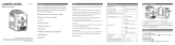
The numbering of the product features shown refers to the illustration
of the tool on the graphic page.
1 Exit opening for laser beam
2 On/Off switch
3 Battery capacity indicator
4 Working without automatic
leveling indicator
5 Button for vertical line
operating mode
6 Button for horizontal line
operating mode
7 Battery lid
8 Mounting slot
9 Tripod mount 1/4”
10 Tripod mount 5/8”
11 Serial number
12 Laser warning label
13 Tool Mount
14 Fastening slot
15 Magnets
16 L-bracket*
17 Bracket with Ceiling grid
clip (BM 3)*
18 Ceiling grid clip*
19 Magnetic Rotating Mount
(RM 1)*
20 Magnetic Rotating Mount
w/ Fine Adjust (RM 2)*
21 Positioning device (BM 1)*
22 Protective pouch*
23 Case*
24 Laser target plate*
25 Compact tripod (BT 150)*
26 Telescopic rod (BP 350)*
27 Laser viewing glasses*
* The accessories illustrated or described are not included as
standard delivery.
Features

-15-
Model Number ................... GLL 100 G / GLL 100 GX
Article number................................. 0601063P1X
Working range
1)
................................. 100 ft (30 m)
Leveling Accuracy ...................±1/8 @ 33 ft (3 mm @ 10 m)
Self-leveling range, typically . . . . . . . . . . . . . . . . . . . . . . . . . . . . . . . . ±4°
Leveling duration, typically ................................< 4 s
Operating temperature ...........14° F to 122° F (-10° C to +50° C)
Storage temperature ............. -4° F to 158° F (-20° C to +70° C)
Relative air humidity, max. ................................90%
Laser class ...............................................2
Laser type ...............................500-540 nm, <10 mW
C
6
......................................................10
Divergence............................. 50X10 mrad (full range)
Tripod mount ........................................1/4”, 5/8”
Batteries.................................. 3 x 1.5 V LR06 (AA)
Operating duration in operating mode
Cross-line operation ..................................... 6 h
Line operation ......................................... 12 h
Weight ......................................1.08 lbs (0.49 kg)
Dimensions .................4.4 x 2.2 x 4.2 in (112 x 55 x 116 mm)
Degree of protection ........ IP 54 (dust and splash water protected)
The tool can be clearly identified with the serial number on the type plate.
1)
The working range can be decreased by unfavorable environmental
conditions (e.g. direct sun exposure).
Technical Data

-16-
Preparation
Inserting/Replacing the Battery
Alkali-manganese batteries are recommended for the measuring tool.
– Fold open the battery lid 7 and insert the batteries. When inserting,
pay attention to the correct polarity according to the representation on
the inside of the battery compartment.
If the batteries become weak, the battery capacity indicator 3 will flash
green. The laser lines will also flash every 10 mins for approx. 5 s.
The measuring tool can be operated for approx. 1 hour after the first
flashing. If the batteries become empty, the laser lines will flash again
before automatic shutoff.
Always replace all batteries at the same time. Only use batteries from
one brand and with the identical capacity.
Remove the batteries from the measuring tool when not using it for
extended periods. When storing for extended periods, the batteries
can corrode and self-discharge.
Working with the BM3
(see figures A – G)
The L-bracket 16 of the BM 3 17 provides easy ability to properly posi-
tion the laser line or lines.
It attaches to job site surfaces as follows:
– To drywall or wood walls using No. 8 screws
– To sit on the floor using retractable feet
– To steel studs using the magnets on the back
– To ceiling grid rails using the clip functionality
It can also be used as a mini tripod.

-17-
Initial Operation
Protect the measuring tool against moisture
and direct sun exposure.
Do not subject the measuring tool to extreme temperatures or
variations in temperature. For example, do not leave it in vehicles
for a long time. In case of large variations in temperature, allow the
measuring tool to adjust to the ambient temperature before putting it
into operation. In case of extreme temperatures or variations in tem-
perature, the accuracy of the measuring tool can be impaired.
Avoid heavy impact to or falling down of the measuring tool.
Damage to the measuring tool can impair its accuracy. After heavy
impact or shock, compare the laser lines with a known horizontal or
vertical reference line.
Switch the tool off during transport. Slide the On/Off switch 2 to
the “Off” position when transporting the measuring tool. This locks the
leveling unit, which can be damaged in case of intense movement.
Operation
•To attach the laser tool, screw the 1/4”-20 mount 13 into the tool
and tighten. Turn the knob and tool together as necessary to properly
position the laser line or lines.
•To adjust the height of the laser lines, adjust the height using the
adjustment knob on the ceiling grid clip 18 of the BM 3 17.
Tip: It is recommended to clean the back of the L-bracket 16 before
mounting via the magnets to make sure you have the optimal mag-
netic hold of the tool on the mounting surface. Cleaning this will re-
duce the amount of interference from any dust or debris between the
magnets 15, L-bracket 16 and the mounting surface on the jobsite.

-18-
Switching On and Off
To save energy, only switch the measuring tool on when you are us-
ing it.
Do not leave the switched-on measuring tool
unattended and switch the measuring tool
off after use. Other persons could be blinded by the laser beam.
– To switch on the measuring tool, slide the On/Off switch 2 to po-
sition “
” (for working without automatic leveling) or to position
“ ” (for working with automatic leveling).
As soon as it is switched on, the measuring tool projects laser lines
from the exit openings 1.
Do not point the laser beam at persons or
animals and do not look into the laser beam
yourself, not even from a long distance.
– To switch off the measuring tool, slide the On/Off switch 2 to posi-
tion “Off ”.
The pendulum unit is locked when the tool is switched off.
When exceeding the maximum permitted operating temperature of
122° F (+ 50° C), the measuring tool switches off to protect the laser
diode. After cooling down, the measuring tool is ready for operation
and can be switched on again.
Automatic Shut-off
When no button on the measuring tool is pressed for approx. 120 min-
utes, the measuring tool automatically switches off to save battery life.
– To switch the measuring tool back on after automatic shutoff, you can
either slide the On/Off switch 2 to position “Off” first and then switch the
measuring tool back on, or press button 6.

-19-
Deactivating the Automatic Shut-off:
– To deactivate automatic shut-off, hold down button 6 for at least
3 s with the measuring tool switched on. When automatic shut-off is
deactivated, the laser lines will flash briefly as confirmation.
Note: When the operating temperature exceeds 113° F (+ 45° C), the
automatic shut-off can no longer be deactivated.
Activating the Automatic Shut-off:
– To activate the automatic shut-off, switch the measuring tool off and
then on again.
Setting the Operating Mode (see figures B1–F1)
The measuring tool has several operating modes between which you
can switch at any time:
– Cross-line operation: The measuring tool generates a horizontal
and a vertical laser line facing frontward.
The laser lines cross at a 90° angle.
– Horizontal line operation: The measuring tool generates a horizontal
laser line facing frontward.
– Vertical line operation: The measuring tool generates a vertical laser
line facing frontward.
When the measuring tool is positioned in the room, the vertical laser
line is displayed on the ceiling beyond the upper laser point.
When the measuring tool is positioned directly against a wall, the
vertical laser line generates an almost completely allround laser line
(360° line).
All modes can be selected both with and without automatic leveling.

-20-
If the measuring tool is outside of the self-leveling range, the laser
lines will flash quickly.
If during work with automatic leveling you switch to the “working with-
out automatic leveling” mode (On/Off switch 2 in position “
”), the
first combination of this mode’s lines is always activated.
Working with Automatic Leveling
Sequence of
actions
Horizontal line
operation
Vertical line
operation
Indicator 3 for
battery capacity
Indicator 4 for
working without
automatic
leveling
Figure
On/Off switch 2 in position
“
”
● ●
Cross-line
operation
green B2
Press button for horizontal
line operating mode 6 once
● —
green
C2,
H
Press button for vertical line
operating mode 5 once
— ●
green I, D2
Press button for vertical line
operating mode 5 once and
horizontal line operating
mode 6 once
●●
green
F1,
F2
Working without Automatic Leveling
The laser lines flash slowly in the “working without automatic leveling”
mode.
If during work without automatic leveling you switch to the “working
with automatic leveling” mode (On/Off switch 2 in position “
”),
the first combination of this mode’s indicators is always activated.
/