Page is loading ...

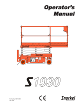
OPERATOR’S MANUAL
CE SPECIFICATIONS
Specifications .......................................................... 2
Introduction .............................................................. 3
Machine Components ............................................................ 4
Machine Controls ................................................................... 6
Safety ........................................................................ 8
Safety Rules And Precautions ............................................... 8
Fall Protection Notice ........................................................... 10
Safety and Instructional Decals ........................................... 12
Operation ................................................................ 14
Prestart ................................................................................ 14
Diesel Engine ....................................................................... 15
Lower Control Operation And Checks.................................. 16
Upper Control Operation and Checks .................................. 17
Set Maintenance Lock ......................................................... 20
Inspect Machine................................................................... 20
Extending the Roll-out Extension Deck ................................ 21
Lowering The Platform Railings ........................................... 22
Emergency Systems And Procedures ................................. 24
Outriggers (3772RT HD) ...................................................... 25
Shutdown Procedure ........................................................... 25
Maintenance ........................................................... 26
Lubrication Diagram ............................................................. 27
Prestart Inspection ................................................ 28
Monthly Inspection ................................................ 29
Quarterly Inspection .............................................. 30
Annual Inspection ..................................................31
Troubleshooting ..................................................... 32
Serial Plate .......................................................................... 32
Transport and Lifting Instructions........................ 34
Lifting Instructions ................................................................ 34
Unloading Procedures........................................... 36
Towing the Machine ............................................................. 37
Brake Release for Towing or Winching ................................. 37
3072RT | 3772RT
3772RT HD
Scissorlift
Serial # 3072RT: 9201000 - Up
Serial # 3772RT: 9301000 - Up
91741R1
May 2008
1
7
7
5
P
a
r
k
S
t
r
e
e
t,
Su
i
t
e
7
7
S
e
l
m
a
,
C
a
l
i
f
o
r
n
i
a
9
3
66
2
Ph
o
n
e
:
(
5
5
9
)
8
9
1
-
2
4
8
8
F
a
x
:
(
5
5
9
)
8
9
1
-
2
4
9
3
ART_2726

Operator's Manual - 3072RT | 3772RT | 3772RT HD May 2008
Page 2
SPECIFICATIONS
Working Height*
Platform Height
Platform Entry Height
Stowed Height
Rails Folded Down
Rails Up
Maximum Occupants
Lift Capacity (Evenly Distributed)
Maximum Operating Inclination
Roll-out Deck Capacity
Platform Dimensions
With Roll-Out Deck Extended
With Roll-Out Deck Retracted
Deck Width
Guardrail Height
Toeboard Height
Roll-out Deck Length
Overall Length
Overall Width
Wheel Base
Wheel Track
Turning Radius Inside
Outside
0 m/s wind
12.5 m/s wind
Ground Clearance
Machine Weight** (Unloaded) (Approx.)
Drive System (Proportional)
Drive Speed (Platform Elevated)
Drive Speed (Platform Lowered)
Lift/Lower Speed (Approx.)
Gradeability
Ground Pressure/Wheel (Maximum)
Wind Speed (Maximum)
Noise Level
Tire Size-
Standard
12 Ply Foam-Filled (Option)
Wheel Load
Wheel Lug Nut Torque
Hydraulic Pressure Main System
Lift System
Steer
Hydraulic Fluid Capacity
Fuel Capacity
Power System – Voltage
Alternator (Lighting Coil)
Engine Availability
Meets requirements of CE.
*Metric equivalent of working height adds 2 m (6.6 ft.) to platform height.
**Weight may increase with certain options or country standards.
3072RT 3772RT 3772RT HD
2 Wheel Drive Standard, 4 Wheel Drive Option
26.0-12.0-380 26.0-12.0-380 26.0-12.0-380
Kubota D905E, 20 HP (14.9kW), Diesel, Liquid Cooled
36.6 ft*
30.0 ft
54 in
108.5 in
78.5 in
3
2
1,000 lb
400 lb
158 in
110 in
60 in
43.5 in
6.0 in
48 in
117.25 in
72 in
86.0 in
60.5 in
73.25 in
14 ft 2.5 in
9.5 in
7868 lb**
0 – 0.4 mph
0 – 4.0 mph
91 psi
28 mph 28 mph 28 mph
2,722 lb
75-85 ft/lb
2800 psi
2500 psi
1500 psi
23 GAL
15 GAL
3° 3° up to 9.1 m (30 ft.)3° up to 9.1 m (30 ft.)
1.5° up to 11.28 m (37 ft.) 1.5° up to 11.28 m (37 ft.)
11.14 m*
9.14 m
1.4 m
2.75 m
1.99 m
3
2
454 kg
181 kg
4.01 m
2.79 m
1.52 m
1.10 m
15.0 cm
1.22 m
2.98 m
1.83 m
2.18 m
1.54 m
1.86 m
4.33 m
24 cm
3203 kg**
0 –0.6 km/h
0 – 6.4 km/hr
6.4 kg/cm²
12.5 m/sec
86 dB 86 dB 86 dB
12.5 m/sec 12.5 m/sec
1235 kg
102-115 Nm
193 bar
172 bar
103 bar
87 liters
57 liters
12 Volts DC
40 Amp
26 sec / 28 sec 28 sec / 31 sec 28 sec / 31 sec
45% / 24.2° 40% / 21.5° 40% / 21.5°
Foam-Filled
750 lb
400 lb
158 in
110 in
60 in
43.5 in
6.0 in
48 in
117.25 in
72 in
86.0 in
60.5 in
73.25 in
14 ft 2.5 in
9.5 in
7,975 lb**
0 – 0.4 mph
0 – 4.0 mph
97 psi
2,921 lb
75-85 ft/lb
3000 psi
2500 psi
1500 psi
23 GAL
15 GAL
43.6 ft*
37 ft
61 in
105.75 in
74 in
2
2
340 kg
181 kg
4.01 m
2.79 m
1.52 m
1.10 m
15.0 cm
1.22 m
2.98 m
1.83 m
2.18 m
1.54 m
1.86 m
4.33 m
24 cm
3589 kg**
0 –0.6 km/h
0 – 6.4 km/hr
6.8 kg/cm²
1325 kg
102-115 Nm
207 bar
172 bar
103 bar
87 liters
57 liters
12 Volts DC
40 Amp
13.28 m*
11.28 m
1.5 m
2.62 m
1.88 m
2
2
Foam-Filled
1,000 lb
400 lb
158 in
110 in
60 in
43.5 in
6.0 in
48 in
140 in
73.25 in
86.0 in
60.5 in
73.25 in
14 ft 2.5 in
9.5 in
8,585 lb**
0 – 0.4 mph
0 – 4.0 mph
100 psi
2,996 lb
75-85 ft/lb
3000 psi
2500 psi
1500 psi
23 GAL
15 GAL
43.6 ft*
37 ft
61 in
105.75 in
74 in
3
3
454 kg
181 kg
4.01 m
2.79 m
1.52 m
1.10 m
15.0 cm
1.22 m
3.56 m
1.86 m
2.18 m
1.54 m
1.86 m
4.33 m
24 cm
3863 kg**
0 –0.6 km/h
0 – 6.4 km/hr
7.0 kg/cm²
1359 kg
102-115 Nm
207 bar
172 bar
103 bar
87 liters
57 liters
12 Volts DC
40 Amp
13.28 m*
11.28 m
1.5 m
2.62 m
1.88 m
3
3
Foam-Filled

May 2008 Operator's Manual - 3072RT | 3772RT | 3772RT HD
Page 3
INTRODUCTION
This Operator’s Manual has been designed to provide you, the
customer, with the instructions and operating procedures essential
to properly and safely operate your MEC Self-Propelled Scissors for
its intended purpose of positioning personnel, along with their
necessary tools and materials to overhead work locations.
The operator’s manual must be read and understood prior to
operating your MEC self-propelled scissors. The user/operator
should not accept operating responsibility until he/she has
read and understands the operator’s manual as well as having
operated the MEC scissor lift under supervision of an autho-
rized, trained and qualified operator.
It is essential that the operator of the aerial work platform is
not alone on the workplace during operation.
Modifications of this machine from the original design and
specifications without written permission from MEC are strictly
forbidden. A modification may compromise the safety of the
machine, subjecting operator(s) to serious injury or death.
Your MEC Scissor Lift has been designed, built, and tested to
provide safe, dependable service. Only authorized, trained and
qualified personnel should be allowed to operate or service the
machine.
MEC, as manufacturer, has no direct control over machine applica-
tion and operation. Proper safety practices are the responsibility of
the user and all operating personnel.
If there is a question on application and/or operation contact:
MEC Aerial Platform Sales Corp.
1775 Park Street, Suite 77 • Selma, CA 93662 USA
Ph: 1-800-387-4575 • 559-891-2488 • Fax: 559-891-2448
www.mecawp.com

Operator's Manual - 3072RT | 3772RT | 3772RT HD May 2008
Page 4
Machine Components
ART_2727
REAR
FRONT
FRONT
3072RT
3772RT HD
Work
Platform
Extension Deck
Guardrails
Entry
Ladder
Limit
Switch
Outriggers
(option)
Scissor
Assembly
(Beams)
Maintenance
Lock
Power
Module
Control
Module
Lift
Cylinder
Lift
Cylinder
Document Case
Upper
Controls
Extension Deck
Lock Handle
Lower
Controls
Emergency
Lowering Cable
3072RT

May 2008 Operator's Manual - 3072RT | 3772RT | 3772RT HD
Page 5
ART_2728
Control Module
Power Module
Battery
Disconnect Switch
Alarm
12 Volt DC Battery
3772RT Emergency Lowering
12 Volt DC Battery
Engine Electrical
3772RT Emergency
Lowering Switch
Lower Controls
Hydraulic
Reservoir
Overflow
Reservoir
Radiator
Fuel
Reservoir
Hydraulic Fluid
Filter
Engine Air Intake
Engine Air Filter
Hydraulic Fluid
Sight Gauge
Hydraulic Fluid
Pump
Engine
Hydraulic
Manifold
Outrigger
Manifold
Motor Control
Module
Machine Components

Operator's Manual - 3072RT | 3772RT | 3772RT HD May 2008
Page 6
CONTROL DESCRIPTION
1 Emergency Use to stop all functions in an emergency.
Stop Button Push for emergency stop. To reset turn clockwise.
2 Keyswitch Select BASE position to control operation of machine using the lower controls.
Select PLATFORM position to control operation of machine using the upper control
box.
3 Preheat Use to heat glow plugs in cold hard-start conditions.
4 Start Switch Press the switch to start the engine. Release switch when engine starts running.
5 Engine Stop Switch Press the switch to shut off engine from lower controls.
6 Throttle Switch Press the switch to activate high engine speed before raising platform from lower
controls.
7 Raise Switch Use to control the lift of the platform from the base panel, when BASE position is
selected.
8 Lower Switch Use to control lowering of the platform from the lower controls when BASE position
is selected.
9 N/A Hole Plugged
10 Hour Meter Indicates total elapsed time the engine has been operated.
11 Circuit-breakers Pops out when there is excessive electrical load in the 12-volt control circuit. Push in
to reset (see Service and Parts Manual).
12 Battery Disconnect Disconnects battery power supply. Turn
OFF
and padlock to secure machine from
Switch unauthorized use.
Machine Controls
ART_2729
Emergency Stop
Hour Meter
Circuit Breakers
10
Preheat
3
Start
4
1
Keyswitch
Lower
(Green)
Raise
(Green)
2
Battery
Disconnect
12
7
8
Engine Stop
(Red)
Throttle
(Green)
6
5
11
Hole Plugged
9

May 2008 Operator's Manual - 3072RT | 3772RT | 3772RT HD
Page 7
CONTROL DESCRIPTION
1 Emergency Stop Push to stop all functions in emergency. Reset by turning Button clockwise..
2 Start Switch Turn key to start the engine. Switch will return to RUN position for normal operation.
Turn key to
OFF position
to shut engine down.
3 Preheat Use to heat glow plugs in cold hard-start conditions.
4 Mode Select Desired selection will allow either the lift or drive function using controller handle.
5 Enable Bar Must be depressed to activate drive, steer, and lift functions.
6 Joystick DRIVE: Controls forward and reverse machine travel at stepped speeds.
LIFT: With enable switch depressed, moving controller handle towards the operator
will provide proportional platform lift. Moving the handle away from the operator will
provide platform lowering at a fixed speed.
7 Steering Push Steer Rocker Switch (thumb) to the left and hold to turn steer wheels to the
left, right to turn steer wheels to the right.
8 Speed Switch HIGH TORQUE selection will provide extra driving torque and reduce speed.
MID RANGE selection will provide medium driving torque and speed.
HIGH SPEED selection will provide high machine speed when platform is under
approximately 10 Ft. (3 m).
9 Horn Press button to sound warning horn.
10 Overload Indicator Lamp
ON
indicates platform overloaded.
11 Generator Switch Turn switch
ON
to engage optional A/C generator. Drive and Lift functions
(Option) are disabled when generator is on.
12 Indicator Lamp Lamp
ON
indicates outriggers are UP and machine will drive.
(3772RT HD) Lamp
OFF
indicates outriggers are DOWN and machine will not drive.
13 Outrigger Switch Push toggle switch UP to RETRACT (raise) the outriggers.
(3772RT HD) Push toggle switch DOWN to EXTEND (lower) the outriggers.
Machine Controls
ART_2730
9
1
7
3
0
7
1
5
6
Emergency Stop
Joystick
Enable Bar
Mode Select
Steering
Speed / Torque
Drive Enabled Indicator
(3772RT HD)
Horn
Outrigger Extend/Retract
(3772RT HD)
1
9
Generator (Option)
11
Preheat
3
Overload Indicator Lamp
10
Start Switch
2
12
13
6
5
7
4
8

Operator's Manual - 3072RT | 3772RT | 3772RT HD May 2008
Page 8
SAFETY
Failure to read, understand, and follow all safety rules, warnings, and instructions will
unnecessarily expose you and others to dangerous situations. For your safety and the
safety of those around you, you must operate your machine as instructed in this manual.
You, the operator, are the single most important factor for safety when using any piece
of equipment. Learn to operate your machine in a safe manner.
To help you recognize important safety information, we have identified warnings and
instructions that directly impact on safety with the following signals:
Indicates an imminently hazardous situation which, if not avoided, will result in death or
serious injury. This signal word is limited to the most extreme situations.
Indicates a potentially hazardous situation which, if not avoided, could result in death or
serious injury.
Indicates a potentially hazardous situation which, if not avoided, may result in minor or
moderate injury. It may also be used to alert against unsafe practices.
Indicates a situation which, if not avoided, may result in damage to the equipment.
Safety Rules And Precautions
MEC designs self-propelled scissor lifts to be safe and reliable. They are intended to
position personnel, along with their necessary tools and materials to overhead work
locations.
The owner/user/operator of the machine should not accept responsibility for the opera-
tion of the machine, unless properly trained.
DO NOT DRIVE NEAR
DROP-OFFS, HOLES
OPEN ELEVATOR SHAFTS,
AND LOADING DOCKS.
DO NOT ELEVATE PLATFORM ON
UNEVEN OR SOFT SURFACES
DO NOT DRIVE ONTO UNEVEN OR
SOFT SURFACES WHEN ELEVATED.
DO NOT RAISE
PLATFORM IN
WINDY OR GUSTY
CONDITIONS.
TIPOVER HAZARDS
DO NOT RAISE PLATFORM
ON SLOPE, OR DRIVE
ONTO SLOPE WHEN ELEVATED.
ART_2349

May 2008 Operator's Manual - 3072RT | 3772RT | 3772RT HD
Page 9
♦♦
♦♦
♦ Only authorized, trained and qualified personnel should operate the machine.
♦♦
♦♦
♦ NEVER fasten a fall protection lanyard to an adjacent structure while on the platform.
♦♦
♦♦
♦ Make sure that the platform entry is properly closed and secure before operating the machine from the platform.
♦♦
♦♦
♦ NEVER exceed platform rated capacity. Review the Specifications table (see page 2) regarding model capacities
and dimensions.
♦♦
♦♦
♦ Before operating the machine, read and understand all safety and control information found on the machine and in
this manual.
♦♦
♦♦
♦ When operating the machine follow all safety and control information found on the machine and in this manual.
♦♦
♦♦
♦ Evenly distribute loads placed on the platform.
♦♦
♦♦
♦ NEVER use scaffolding, ladders or similar items to extend your reach while on the platform.
♦♦
♦♦
♦ NEVER climb down the beam assembly while the platform is elevated.
♦♦
♦♦
♦ Towing or winching the machine requires that the brake be released. When the brake is released, there is no
means to stop the machine’s travel. MEC recommends using this procedure only in cases of emergency, and only
for a short distance. Be on guard against machine runaway on sloping surfaces. Movement speed shall not exceed
5 MPH (8.0 kph).
♦♦
♦♦
♦ NEVER attempt to open any hydraulic line or component without first relieving all system pressure.
♦♦
♦♦
♦ NEVER alter, modify, or disable any safety devices or interlocks.
♦♦
♦♦
♦ NEVER recharge the battery near sparks or open flames. Lead-acid batteries generate EXPLOSIVE HYDROGEN
GAS. Always wear safety glasses.
♦♦
♦♦
♦ NEVER use the machine outdoors during electrical storms or in high wind situations.
♦♦
♦♦
♦ Only elevate the platform when the machine is on a firm, level surface.
♦♦
♦♦
♦ SECURE all tools and other loose items to prevent injury to persons working on or below the platform.
♦♦
♦♦
♦ Precautions should be taken to prevent unauthorized personnel from operating the platform with the ground
controls while the platform is in use.
♦♦
♦♦
♦ Unassisted loading or unloading of scissorlift from a truck or trailer is not recommended.
♦♦
♦♦
♦ Before disengaging brakes or disconnecting from a tow vehicle, ensure that the machine cannot roll.
♦♦
♦♦
♦ Complete the inspections at designated intervals.
♦♦
♦♦
♦ Use of the machine as a crane to lift oversized or hanging loads is prohibited.
♦♦
♦♦
♦ Always ensure that the route and areas are clear before driving, lifting or lowering.
♦♦
♦♦
♦ It is recommended to avoid sudden braking or steering. Go slowly and leave more maneuvering room during cold
weather operation.
♦♦
♦♦
♦ Only lower the outriggers when the machine is on a firm, level surface. The surface must be capable of supporting
the maximum ground pressure per wheel/outrigger (see specifications).
♦♦
♦♦
♦ Do not raise the platform unless all four outriggers are properly lowered and the machine is level.
♦♦
♦♦
♦ Do not adjust outriggers while platform is raised.
♦♦
♦♦
♦ Do not drive while outriggers are lowered.

Operator's Manual - 3072RT | 3772RT | 3772RT HD May 2008
Page 10
Fall Protection Notice
The Guardrail System around the perimeter of the platform is the
fall protection system for self-propelled elevating work platforms. It
is prohibited to use an Aerial Work Platform manufactured by MEC
with any portion, or all, of the guardrails removed.
ART_2350
Optional Lanyard Anchorage Points
Guardrails
Entry to be secured by
Safety Chain or Optional Gate
♦♦
♦♦
♦ ELECTROCUTION HAZARD!!! THIS MACHINE IS NOT INSULATED!!
♦♦
♦♦
♦ Maintain safe clearance from electrically charged conductors (power lines) and apparatus. You must allow for
machine sway (side to side movement) when elevated and electrical line movement. This machine does not
provide protection from contact with, or proximity to, an electrically charged conductor.
♦♦
♦♦
♦ You must maintain a CLEARANCE OF AT LEAST 10 FEET (3.05 m) between any part of the machine, or its load, and
any electrical line or apparatus carrying over 300 Volts up to 50,000 Volts. One foot (30.5 cm) additional clearance
is required for every additional 30,000 Volts.
♦♦
♦♦
♦ DEATH OR SERIOUS INJURY will result from contact with or inadequate clearance from any electrically charged
conductor.
♦♦
♦♦
♦ Observe Minimum Safe Approach Distance as illustrated on next page.
Lanyard anchorage points
are recommended for work
positioning restraints only.
Use of fall arrest systems
attached to anchorage points
on mobile equipment may
cause machine to tip,
resulting in serious injury or
death.

May 2008 Operator's Manual - 3072RT | 3772RT | 3772RT HD
Page 11
MINIMUM SAFE APPROACH DISTANCE (M.S.A.D.)
to energized (exposed or insulated) power lines and parts.
M.S.A.D. = MINIMUM SAFE APPROACH DISTANCE
DENOTES PROHIBITED ZONE
DANGER:
CAUTION:
DO NOT ALLOW MACHINE, PERSONNEL OR CONDUCTIVE MATERIALS
INSIDE PROHIBITED ZONE.
MAINTAIN M.S.A.D. FROM ALL ENERGIZED LINES AND PARTS AS WELL
AS THOSE SHOWN.
ASSUME ALL ELECTRICAL PARTS AND WIRES ARE ENERGIZED
UNLESS KNOWN OTHERWISE.
DIAGRAMS SHOWN ARE ONLY FOR PURPOSES OF ILLUSTRATING
M.S.A.D. WORK POSITIONS, NOT ALL WORK POSITIONS.
VOLTAGE RANGE MINIMUM SAFE APPROACH DISTANCE
(Phase to Phase)
0 to 300V
Over 300V to 50KV
Over 50KV to 200KV
Over 200KV to 350KV
Over 350KV to 500KV
Over 500KV to 750KV
Over 750KV to 1000KV
AVOID CONTACT
10
15
20
25
35
45
3.05
(Feet) (Meters)
4.60
6.10
7.62
10.67
13.72
ART_2351

Operator's Manual - 3072RT | 3772RT | 3772RT HD May 2008
Page 12
Safety and Instructional Decals
ART_2731
90717 EUR
8911
90930
91384
(3072ES)
91385
(3772ES)
91384
(3072ES)
91385
(3772ES)
91387
(3772ES)
91386
(3072ES)
91385
454 kg
487 kg 261 kg
33 kg
273 kg 181 kg
400N
454 kg
214 kg 181 kg 33 kg
273 kg 181 kg
400N
91
3
85
4
5
4
k
g
4
8
7
k
g
2
6
1
k
g
3
3
k
g
2
7
3
k
g
1
8
1
k
g
4
0
0
N
4
5
4
k
g
2
1
4
k
g
1
8
1
k
g
3
3
k
g
2
7
3
k
g
1
8
1
k
g
4
0
0
N
9
1
3
8
5
4
5
4
k
g
4
8
7
k
g
26
1
k
g
3
3
k
g
2
7
3
k
g
1
8
1
k
g
4
0
0
N
4
5
4
k
g
21
4
k
g
18
1
k
g
3
3
k
g
2
7
3
k
g
1
8
1
k
g
4
0
0
N
91385
454 kg
487 kg 261 kg
33 kg
273 kg 181 kg
400N
454 kg
214 kg 181 kg 33 kg
273 kg 181 kg
400N
(EACH OUTRIGGER)
9465
90725
91388
(3072ES - One Side)
(X2)
(X2)
(X4)
(X4)
(3772ES - Both Sides)
7982
91084
(3072ES)
WARNING
90725
REPLACE TIRES WITH MANUFACTURER’S
EQUIPMENT ONLY.
FAILURE TO USE MANUFACTURER’S
TIRES MAY CAUSE MACHINE INSTABILITY.
REFER TO SERVICE AND PARTS MANUAL
FOR REPLACEMENT PART NUMBER.
9910
9910
91586
MEC AERIAL PLATFORM SALES CORP.
1775 PARK STREET, SUITE 77
SELMA, CA, USA
MFG. DATE MODEL NUMBER SERIAL NUMBER MODEL YEAR
MAX. PLATFORM CAPACITY INCLUDING PERSONS
MAX. ALLOWABLE
MANUAL FORCE
MAX.
PLATFORM HEIGHT
MAX. ALLOWABLE
INCLINATION
ELECTRICAL VOLTAGE
MAX. GROUND
PRESSURE PER WHEEL
MAX. LOAD
PER WHEEL MACHINE WEIGHT
90982
XX/XX XXXXXX XXXXXXXXX 20XX
0 m/s
12.5 m/s
XXX kg = X PERSONS + XXX kg EQUIPMENT XXX N X.X m
X.X m
XXX kg = X PERSONS + XXX kg EQUIPMENT XXX N
X.X° x X.X°
100-220 VAC
50/60 Hz
X.X kg/cm² XXX kg XXXX kg
HYDRAULIC OIL
6873
HYD
RA
ULIC OIL
687
3
6873
90721
90722
90730
90721

May 2008 Operator's Manual - 3072RT | 3772RT | 3772RT HD
Page 13
Safety and Instructional Decals
ART_2732
90267
9052
90918EUR
(3772ES)
90918EUR
(3772ES)
90725
8867
9378
(X4)
91729
9910
90732
91728
91730
WARNING
90725
REPLACE TIRES WITH MANUFACTURER’S
EQUIPMENT ONLY.
FAILURE TO USE MANUFACTURER’S
TIRES MAY CAUSE MACHINE INSTABILITY.
REFER TO SERVICE AND PARTS MANUAL
FOR REPLACEMENT PART NUMBER.
90732
DO NOT POWERWASH OR
SPRAY ELECTRONIC
COMPONENTS OR
CONNECTORS.
MOISTURE MAY CAUSE
DAMAGE AND/OR
ERRATIC OPERATION
WARNING
9910
(3072ES - One Side)
(X2)
(3772ES - Both Sides)
7982
7982
91730
91387
(3772ES)
91386
(3072ES)
(X4)
91109
90717 EUR

Operator's Manual - 3072RT | 3772RT | 3772RT HD May 2008
Page 14
Do not operate the machine
if tests reveal a defect.
ART_2356
♦ Ensure that the battery disconnect switch is in the ON posi-
tion. Located in control module, to the left of control panel.
♦ Ensure that EMERGENCY STOP switch on the upper con-
trols is reset. Reset the switch by turning it clockwise.
Prestart
♦ Perform
Prestart Inspection
(see page 28).
OPERATION
Before use each day or at the beginning of each shift, a visual
inspection and functional test shall be performed. Repairs must be
made prior to operating the machine to ensure safe operation.
♦ Ensure that EMERGENCY STOP switch on the lower control
panel is reset. Reset the switch by turning it clockwise.
ART_2506
ART_2507

May 2008 Operator's Manual - 3072RT | 3772RT | 3772RT HD
Page 15
Diesel Engine
Ensure that the EMERGENCY STOP switches at the platform and
lower controls are reset.
Starting a Diesel Engine
Start engine from Lower Control Panel
1. Upper Control Box: Turn the engine start switch to RUN.
ART_2734
ART_2509
Start engine from Upper Control Box
1. Lower Control Box: Turn the key switch to PLATFORM.
ART_2508
4. If engine is cold, press and hold the GLOW button for the
recommended times shown below. With button held, press and
hold START button until engine starts. Release both buttons
once engine starts.
3. Press and hold the START button, releasing when the engine
starts.
2. Lower Control Box: Turn the key switch to BASE.
3. If engine is cold, lift and hold the GLOW switch for the recom-
mended times shown below. With switch held, turn the engine
start switch until engine starts. Release both switches once
engine starts.
2. Upper Control Box: Turn the engine start switch to START,
releasing when the engine starts.
ART_2733
Refer to the following table for some recommended preheat times
for different ambient temperatures:
Preheating Time Ambient Temperature
5 seconds (approx.) Above 50°F (10°C)
10 seconds (approx.) 50°F (10°C) to 23°F (-5°C)
20 seconds Below 23°F (-5°C)
20 seconds Limit Of Continuous Use
ART_2735
ART_2736

Operator's Manual - 3072RT | 3772RT | 3772RT HD May 2008
Page 16
Lower Platform
Press the LOWER button. Release when the desired platform
height is reached.
Test Operation
♦ Lower the platform to the stowed position.
♦ Releasing the button will stop descent.
♦ Pressing the EMERGENCY STOP switch will stop descent.
DO NOT ELEVATE THE
PLATFORM IF THE
MACHINE IS NOT ON A
FIRM LEVEL SURFACE
Lower Control Operation And Checks
Important: BE SURE the area above the machine is clear of
obstructions to allow full elevation of platform.
DO NOT OPERATE the machine if tests reveal a
defect.
ELECTROCUTION HAZARD: observe safety
rules outlined on pages 10-11.
Start the engine.
Emergency Stop
Press the EMERGENCY STOP switch at any time to stop all func-
tions.
♦ Reset the switch by turning it clockwise.
Elevate Platform
1. Press and hold the THROTTLE switch to increase engine
speed.
2. Press and hold the RAISE button to elevate the platform.
Test Operation
♦ Elevate to maximum height.
♦ Releasing the button will stop elevation.
♦ Pressing the EMERGENCY STOP switch will stop elevation.
Inspection
♦ Check for proper operation and hydraulic leaks.
♦ Set the maintenance lock before inspecting any items inside
or around the scissor arms.
♦ Lower the platform to the stowed position.
♦ Turn off engine.
ART_2506
ART_2737

May 2008 Operator's Manual - 3072RT | 3772RT | 3772RT HD
Page 17
Activation of the platform
EMERGENCY STOP switch
will apply brakes immediately.
This may cause unexpected
platform movement as the
machine comes to a sudden
stop. Brace yourself and
secure objects on the
platform during operation of
machine.
4. If equipped, press the horn button to verify proper operation.
3. Upper Control Box: Turn the engine start switch to start the
engine.
Upper Control Operation and Checks
Check that the route of travel to be taken is clear of persons, ob-
structions, debris, holes, and drop offs, and is capable of supporting
the machine.
1. Lower Control Box: Turn the key switch to PLATFORM.
2. Enter platform and close and secure the entry.
Emergency Stop (Platform)
Press the EMERGENCY STOP switch at any time to stop all func-
tions.
♦ Reset the switch by turning it clockwise.
ART_2735
ART_2511
ART_2507
ART_2519
Platform Overload Indicator
The Platform Overload Indicator will light and the platform will not
lift when the sensor detects too much weight in the platform. Refer
to the platform capacity label and adjust the platform load accord-
ingly.
ART_2738
OFF

Operator's Manual - 3072RT | 3772RT | 3772RT HD May 2008
Page 18
Lower Platform
1. Place the MODE SELECT switch in the LIFT position.
2. Move the joystick away from you.
Test Operation
♦ Rate of descent is fixed - platform lowers at same rate re-
gardless of handle position.
♦ Release the joystick or move it to the neutral (center) position
to stop descent.
♦ Pressing the EMERGENCY STOP switch will stop descent.
Elevate Platform
1. Place the MODE SELECT switch in the LIFT position.
2. Squeeze the enable bar and move the joystick toward you.
Test Operation
♦ Rate of lift is proportional and is dependent on the movement
of the joystick.
♦ Elevate to maximum height.
♦ Release the joystick and/or enable bar, or move the joystick
to the neutral (center) position to stop elevation.
♦ Pressing the EMERGENCY STOP switch will stop elevation.
Do Not elevate platform
unless guardrails are
installed and secure.
ART_2363
Steer
Enable
Bar
Proportional
Joystick
Lower
Lift
Forward
Reverse
If the roll-out deck is
extended check for
clearance under deck area
before lowering platform.
Joystick Operation
Function speed is proportional and is controlled by the movement of
the joystick. The further it is moved the faster the speed will be. The
joystick returns to the neutral (center) position when released.
If platform should fail to lower
do not attempt to climb down
the scissor assembly.
Serious injury may result.
ART_2512

May 2008 Operator's Manual - 3072RT | 3772RT | 3772RT HD
Page 19
Drive Speed
Drive speed is selectable when the platform is down. When the
platform is elevated above 10 Feet (3 m) the machine defaults to
MID RANGE and the switch is locked-out (non functioning).
1. HIGH SPEED: allows speeds up to 3 m.p.h. (4.8 km/h).
2. MID RANGE: allows speeds up to 0.4 m.p.h. (0.6 km/h).
3. HIGH TORQUE: use to drive up or down a slope that is too
steep for normal operation.
Drive Forward
1. Place the MODE SELECT switch in the DRIVE position.
2. Squeeze the enable bar and move the joystick away from you.
♦ Drive speed is proportional and is dependent on the move-
ment of the joystick.
♦ Release the enable bar or return the joystick to the center
position to stop.
♦ Pressing the EMERGENCY STOP switch will stop drive.
Drive Reverse
1. Place the MODE SELECT switch in the DRIVE position.
2. Squeeze the enable bar and move the joystick toward you.
♦ Drive speed is proportional and is dependent on the move-
ment of the joystick.
♦ Release the enable bar or return the joystick to the center
position to stop.
♦ Pressing the EMERGENCY STOP switch will stop drive.
Brake
For parking, the brake is automatically applied when the joystick is
in the neutral (center) position.
Steer
IMPORTANT: Always check front steer wheel direction
before driving.
1. Place the MODE SELECT switch in the DRIVE position.
2. Squeeze the enable bar and press the steering switch with
your thumb to steer left or right.
♦ Release the enable bar or steering switch to stop steering.
♦ The wheels will not center themselves after a turn. They
must be returned to the straight-ahead position with the
steering switch.
Check that the route of travel
is clear of persons,
obstructions, debris, holes,
and drop offs, and is capable
of supporting the machine.
ART_2363
Steer
Enable
Bar
Proportional
Joystick
Lower
Lift
Forward
Reverse
ART_2515
ART_2513

Operator's Manual - 3072RT | 3772RT | 3772RT HD May 2008
Page 20
Maintenance Lock In Position
3072RT
3772RT
ART_2416
Set Maintenance Lock
Set the maintenance lock before inspecting any items inside or
around scissor beams, or beneath the platform.
♦ Elevate the platform about halfway.
♦ Rotate the maintenance lock into position.
♦ Lower platform until the scissor assembly is supported by the
maintenance lock.
Inspect Machine
Walk around the machine and inspect for;
♦ frayed cables or wires.
♦ hydraulic fluid leaks.
♦ missing or loose bolts.
♦ proper tire pressure.
♦ missing or loose wheel lug nuts.
♦ weld or structural cracks.
♦ defects or missing parts.
/