Page is loading ...

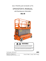
Operator’s Manual
CE/Australian Specifications
Speed Level™
Sigma Lifts - RT Models
Serial Number
11800001 - up
91942R1
May 2010
Specifications . . . . . . . . . . . . . . . . . . . . . . . . . . . . . . . . . . . . . . . . . inside cover
Introduction . . . . . . . . . . . . . . . . . . . . . . . . . . . . . . . . . . . . . . . . . . . . . . . . . . . . . 1
Safety . . . . . . . . . . . . . . . . . . . . . . . . . . . . . . . . . . . . . . . . . . . . . . . . . . . . . . . . . . . 2
Safety Alert Symbols . . . . . . . . . . . . . . . . . . . . . . . . . . . . . . . . . . . . . . . . . . . . . . .3
Fall Protection . . . . . . . . . . . . . . . . . . . . . . . . . . . . . . . . . . . . . . . . . . . . . . . . . . . . .3
Electrocution Hazard . . . . . . . . . . . . . . . . . . . . . . . . . . . . . . . . . . . . . . . . . . . . . . .4
Tip-over Hazards . . . . . . . . . . . . . . . . . . . . . . . . . . . . . . . . . . . . . . . . . . . . . . . . . . .6
Fall Hazards . . . . . . . . . . . . . . . . . . . . . . . . . . . . . . . . . . . . . . . . . . . . . . . . . . . . . . . .7
Collision Hazards . . . . . . . . . . . . . . . . . . . . . . . . . . . . . . . . . . . . . . . . . . . . . . . . . . .7
Additional Safety Hazards . . . . . . . . . . . . . . . . . . . . . . . . . . . . . . . . . . . . . . . . . .8
Battery Safety . . . . . . . . . . . . . . . . . . . . . . . . . . . . . . . . . . . . . . . . . . . . . . . . . . . . . .8
Workplace Inspection . . . . . . . . . . . . . . . . . . . . . . . . . . . . . . . . . . . . . . . . . . . . 9
Functions Test . . . . . . . . . . . . . . . . . . . . . . . . . . . . . . . . . . . . . . . . . . . . . . . . . . . 9
Operating Instructions . . . . . . . . . . . . . . . . . . . . . . . . . . . . . . . . . . . . . . . . . .10
Prestart . . . . . . . . . . . . . . . . . . . . . . . . . . . . . . . . . . . . . . . . . . . . . . . . . . . . . . . . . . 10
Starting Engine from Base Controls . . . . . . . . . . . . . . . . . . . . . . . . . . . . . . . 11
Starting Engine from Platform Controls . . . . . . . . . . . . . . . . . . . . . . . . . . . 12
Base Controls Operation and Test . . . . . . . . . . . . . . . . . . . . . . . . . . . . . . . . . 13
Platform Control Operation and Test . . . . . . . . . . . . . . . . . . . . . . . . . . . . . . 14
Control Lever Operation . . . . . . . . . . . . . . . . . . . . . . . . . . . . . . . . . . . . . . . . . . 15
Leveling Procedure . . . . . . . . . . . . . . . . . . . . . . . . . . . . . . . . . . . . . . . . . . . . . . 17
Shutdown Procedure . . . . . . . . . . . . . . . . . . . . . . . . . . . . . . . . . . . . . . . . . . . . . 17
Deck Extension -- 2684 models only . . . . . . . . . . . . . . . . . . . . . . . . . . . . . . 18
Emergency Systems . . . . . . . . . . . . . . . . . . . . . . . . . . . . . . . . . . . . . . . . . . . . .19
Emergency Stop . . . . . . . . . . . . . . . . . . . . . . . . . . . . . . . . . . . . . . . . . . . . . . . . . 19
Emergency Lowering . . . . . . . . . . . . . . . . . . . . . . . . . . . . . . . . . . . . . . . . . . . . . 19
Fold Down Platform Railings . . . . . . . . . . . . . . . . . . . . . . . . . . . . . . . . . . . . .20
Machine Inspections . . . . . . . . . . . . . . . . . . . . . . . . . . . . . . . . . . . . . . . . . . . .22
Annual Inspection Report . . . . . . . . . . . . . . . . . . . . . . . . . . . . . . . . . . . . . . . . 26
Maintenance . . . . . . . . . . . . . . . . . . . . . . . . . . . . . . . . . . . . . . . . . . . . . . . . . . .27
Routine Maintenance . . . . . . . . . . . . . . . . . . . . . . . . . . . . . . . . . . . . . . . . . . . . 28
Scheduled Maintenance . . . . . . . . . . . . . . . . . . . . . . . . . . . . . . . . . . . . . . . . . . 28
Maintenance Safety . . . . . . . . . . . . . . . . . . . . . . . . . . . . . . . . . . . . . . . . . . . . . . 28
Lubrication . . . . . . . . . . . . . . . . . . . . . . . . . . . . . . . . . . . . . . . . . . . . . . . . . . . . . . 29
Component Locations . . . . . . . . . . . . . . . . . . . . . . . . . . . . . . . . . . . . . . . . . . .30
Full Machine . . . . . . . . . . . . . . . . . . . . . . . . . . . . . . . . . . . . . . . . . . . . . . . . . . . . . 30
Modules . . . . . . . . . . . . . . . . . . . . . . . . . . . . . . . . . . . . . . . . . . . . . . . . . . . . . . . . . 31
Upper Controls . . . . . . . . . . . . . . . . . . . . . . . . . . . . . . . . . . . . . . . . . . . . . . . . . . . 32
Lower Controls . . . . . . . . . . . . . . . . . . . . . . . . . . . . . . . . . . . . . . . . . . . . . . . . . . . 33
Decals . . . . . . . . . . . . . . . . . . . . . . . . . . . . . . . . . . . . . . . . . . . . . . . . . . . . . . . . . .34
Troubleshooting . . . . . . . . . . . . . . . . . . . . . . . . . . . . . . . . . . . . . . . . . . . . . . . .36
Serial Plate Location . . . . . . . . . . . . . . . . . . . . . . . . . . . . . . . . . . . . . . . . . . . . . . 37
Serial Plate Description . . . . . . . . . . . . . . . . . . . . . . . . . . . . . . . . . . . . . . . . . . . 37
Transport and Lifting Instructions . . . . . . . . . . . . . . . . . . . . . . . . . . . . . . . .38
Loading . . . . . . . . . . . . . . . . . . . . . . . . . . . . . . . . . . . . . . . . . . . . . . . . . . . . . . . . . . 38
Disengage Brakes before Towing or Winching . . . . . . . . . . . . . . . . . . . . 38
Engage Brakes before Driving . . . . . . . . . . . . . . . . . . . . . . . . . . . . . . . . . . . . 38
Lifting and Tie Down Instructions . . . . . . . . . . . . . . . . . . . . . . . . . . . . . . . . . 40

—Specifications—
2684RT 3084RT
Working Height* 32 ft* 10.0 m* 36 ft* 11.0 m*
Platform Height 26 ft 7.9 m 30 ft 9.0 m
Stowed Height Rails Up 107 in 2.72 m 105 in 2.67 m
Rails Folded Down 72 in 1.83m 70 in 1.78 m
Maximum Occupants 0 m/s wind 5 5
45 km/h (12.5 m/s) wind 5 5
On Slide-Out Extension 2 N/A
Lift Capacity 1700 lbs 770 kg 1500 lbs 680 kg
Slide-Out Deck Capacity 700 lbs 320 kg N/A
Platform Dimensions Length (inside rails) 12 ft 2 in 3.71 m 14 ft 4.27 m
Length (platform extended) 16 ft 2 in 4.93 m N/A
Platform Width (inside rails) 72 in 1.83 m 72 in 1.83 m
Guardrail Height 43.5 in 1.1 m 43.5 in 1.1 m
Toeboard Height 6 in 15 cm 6 in 15 cm
Overall Length 13 ft 2 in 4.0 m 14 ft 6 in 4.4 m
Overall Width 84 in 2.13 m
Wheel Base 100 in 2.54 m
Wheel Track 72 in 1.83 m
Turning Radius Inside 8 ft 2.44 m
Outside 16 ft 8 in 5.08 m
Ground Clearance 10 in 25 cm
Machine Weight** (Unloaded)(Approximate) 7800 lb** 3535 kg** 8100 lb** 3674 kg**
Drive System (Proportional)
Drive Speed - Platform elevated 0-.4 mph 0-.6 km/h
Drive Speed - Platform lowered 0-3.2 mph 0-5 km/h
Lift/Lower Speeds (Approximate) 35 sec/40 sec
Gradeability 40% 22°
Ground Pressure/Wheel (Maximum) 90 psi 6.3 kg/cm 94 psi 6.6 kg/cm
Wheel Load 2855 lb 1295 kg 2965 lb 1345 kg
Wind Speed (Maximum) 28 mph 45 km/h (12.5 m/s)
Tire Size - Standard 26 x 12D / 380NHS
Tire Pressure Foam-filled tires are standard
Wheel Lug Nut Torque 75-85 ft/lb 102-115 Nm
Hydraulic Pressure Main System 2800 psi 193 bar
Lift System 2800 psi 193 bar
Steering System 2000 psi 138 bar
Hydraulic Fluid Capacity 23 gallon 87 liters
Engine Kubota D1105E, 25HP (18.6 kW), Diesel, Liquid Cooled
Noise Level 86 dB maximum
Maximum Vibration
does not exceed 2.5 m/sec
2
at operator’s position
Ambient Operating Range -30° C minimum; 50° C maximum
Leveling Side/Side 14°
Fore/Aft 10°
Operating Inclination Manual and self-leveling, side/side to 14°, fore/aft to 10°
Brakes Dual Rear Wheel Multi-disc
Meets requirements of CE
EN280:2001 + A2:2009 and Australian Standard AS1418.10(Int)--2004 Part 10: Elevated
Work Platforms. Speed Level™ is a trademark of MEC.
*Working Height adds 6 feet (2 m) to platform height.
**Weight may increase with certain options or country standards.

91942R1– May 2010 Page 1
Speed Level™ Sigma Lifts - RT Models Introduction
Introduction
This Operator’s Manual has been designed to provide you with the instructions and operating procedures essential to properly and
safely operate your MEC Aerial Work Platform for its intended purpose of positioning personnel, along with their necessary tools and
materials, to overhead work locations.
The Operator’s Manual must be read and understood prior to operating your MEC Aerial Work
Platform. The user/operator should not accept operating responsibility until he/she has read and
understands the operator’s manual as well as having operated the MEC Aerial Work Platform under
supervision of an authorized, trained and qualified operator.
It is essential that the operator of the aerial work platform is not alone on the workplace during
operation.
Modifications of this machine from the original design and specifications without written permission
from MEC are strictly forbidden. A modification may compromise the safety of the machine, subjecting
operator(s) to serious injury or death.
Your MEC Aerial Work Platform has been designed, built, and tested to provide safe,
dependable service. Only authorized, trained and qualified personnel should be allowed to
operate or service the machine.
MEC, as manufacturer, has no direct control over machine application and operation. Proper
safety practices are the responsibility of the user and all operating personnel.
Use of this machine in Europe must comply with
CE standard EN280:2001 + A1 and applicable
government regulations. Use in Australia must comply with
Australian Standard
AS1418.10(Int)--2004 Part 10.
Use only MEC-approved replacements parts in the repair and maintenance of this machine.
If there is a question on application and/or operation contact:
MEC Aerial Platform Work Platforms
1401 S. Madera Avenue, Kerman, CA 93630 USA
Toll Free: 1 - 877 - 632 - 5438
Phone: 1 - 559 - 842 - 1500
Fax: 1 - 559 - 842 - 1520
www.MECawp.com

Page 2 91942R1– May 2010
Speed Level™ Sigma Lifts - RT Models Safety
Safety
DO NOT operate this machine until you have read and understood this manual, have
performed the Pre-Start Inspection, Routine Maintenance, and Functions Test, have
inspected the workplace for hazards, and have learned the operating procedures for this
machine.
Failure to read, understand and follow all safety rules, warnings, and instructions will
unnecessarily expose you and others to dangerous situations. For your safety and the safety of
those around you, you must operate your machine as instructed in this manual.
MEC designs aerial work platforms to be safe and reliable. They are intended to position
personnel, along with their necessary tools and materials, to overhead work locations. The
owner/user/operator of the machine should not accept responsibility for the operation of the
machine unless properly trained.
Never perform work or inspection on the machine with the platform elevated without first
blocking the boom assembly (see Maintenance Safety on page 28).

91942R1– May 2010 Page 3
Speed Level™ Sigma Lifts - RT Models Safety
Safety Alert Symbols
MEC manuals and decals use symbols and colors to help you recognize important safety,
operation and maintenance information.
RED – Indicates an imminently hazardous situation which, if not avoided, will result in death or serious
injury.
ORANGE – Indicates a potentially hazardous situation which, if not avoided, could result in death or
serious injury.
YELLOW with alert symbol – Indicates a potentially hazardous situation which, if not avoided, may
result in minor or moderate injury.
YELLOW without alert symbol – Indicates a potentially hazardous situation which, if not avoided, may
result in property damage.
Fall Protection
Operators must comply with employer, job site and governmental rules regarding the use of
personal protective equipment.
If required by your employer or job site, use personal fall protection equipment (PFPE) when
operating this machine.
All PFPE must comply with applicable governmental regulations, and must be inspected and
used in accordance with the PFPE manufacturer’s instructions.
ALWAYS wear an approved fall protection properly attached to a designated anchorage point
when driving or operating the machine. Attach only one fall restraint to each anchorage point.
Art_2836

Page 4 91942R1– May 2010
Speed Level™ Sigma Lifts - RT Models Safety
Electrocution Hazard
ELECTROCUTION HAZARD!!! THIS MACHINE IS NOT INSULATED!
DEATH OR SERIOUS INJURY will result from contact with or inadequate clearance from any electrically
charged conductor.
You must maintain a CLEARANCE OF AT LEAST 10 FEET (3.05 m) between any part of the machine, or its
load, and any electrical line or apparatus carrying over 300 Volts up to 50,000 Volts. One foot (30.5 cm)
additional clearance is required for every additional 30,000 Volts.
Observe Minimum Safe Approach Distance.
DO NOT work in close proximity to, or in contact with, energized power lines and electrical
equipment. This machine is not insulated and WILL NOT protect the operator from injury or
the machine from damage.
Refer to the following diagram and all applicable governmental regulations for the minimum
safe distances from energized power lines and electrical equipment.
DO NOT touch the machine if it contacts energized power lines.
Personnel in the platform:
• Move away from the platform rails,
• DO NOT attempt to operate the machine, and
• DO NOT touch any part of the machine until energized power lines are shut
off.
Personnel on the ground:
•DO NOT approach the machine and
• DO NOT touch or attempt to operate the machine until energized power
lines are turned off.
Do not operate the machine during electrical storms or lightning.
DO NOT use the machine as a ground for welding unless properly equipped with a weld line
to platform option.
ART_3070
ART_3060

91942R1– May 2010 Page 5
Speed Level™ Sigma Lifts - RT Models Safety
Minimum Save Approach Distance
ART_3265
No go zone
Spotter
required
zone
Personal
protection
barriers
FRONT VIEW
(a) Distribution lines up to and including 133 kV
SIDE VIEW
Sag
Variations
in sag
6.4 m
6.4 m
3 m
3 m
(b) Transmission lines greater than 133 kV
No go zone
Spotter
required
zone
Sway
FRONT VIEW SIDE VIEW
Sag
Variations
in sag
Sag
Sag
10 m
8 m
10 m
8 m
LEGEND
CLEARANCES FROM LIVE AERIAL CONDUCTORS
= No shading, in the front views, indicates no proximity requirements
= Light shading indicates spotter is required
= Heavy shading indicates the NO GO ZONE
(a) Affected area
Min. volts
Min. volts
Max. volts
Higher voltage
Lower voltage
(b) Avoid simultaneous contact across
areas of high potential difference
5000 V
20000 V
15000 V
10000 V
5000 V

Page 6 91942R1– May 2010
Speed Level™ Sigma Lifts - RT Models Safety
Tip-over Hazards
DO NOT exceed the maximum platform capacity (see Specifications). The weight of options
and accessories will reduce the rated platform capacity and must be factored into the total
platform load. Refer to the decals on the options.
DO NOT elevate the platform when the machine is on a surface that is soft, non-planar,
or
exceeds the leveling range of the machine.
The tilt alarm will sound when the machine is off level. If the alarm sounds when the
platform is lowered, DO NOT attempt to elevate the platform. Carefully lower, re-level
the machine, or move the machine to a surface within the leveling range.
STOP if the alarm sounds and the red light illuminates when the platform is raised. Use
extreme caution to lower the platform.
Driving: DO NOT drive the machine on a slope that exceeds the maximum uphill or downhill
slope rating. Slope rating applies to machines in the stowed position.
Driving in stowed position: use extreme care and reduce speed when driving across uneven
terrain, debris, unstable or slippery surfaces, and near holes or drop-offs.
Driving with the platform elevated: DO NOT drive on or near uneven terrain, unstable
surfaces, curbs, drop-offs or other hazardous conditions.
DO NOT push off or pull toward any object outside the platform.
DO NOT elevate the platform when wind speeds are in excess of 28 m.p.h. (12.5 m/s). If wind
speeds exceed 28 m.p.h. (12.5 m/s) when the platform is elevated, carefully lower the platform
and discontinue operation.
DO NOT increase the surface area of the platform (i.e. cover the rails with tarp or plywood).
Increased surface area exposed to the wind will decrease machine stability.
DO NOT attach overhanging loads or use the machine as a crane.
NEVER transport tools and materials unless they are firmly secured. Secure all tools and loose
materials.
NEVER alter or disable any machine components.
NEVER replace any part of the machine with items of different weight or specification.
NEVER modify or alter the work platform without written permission from MEC.
NEVER place ladders or scaffolds in the platform or against any part of the machine.
NEVER use the machine on a moving or mobile surface or vehicle.
Ensure that all tires are in good condition and lug nuts are properly torqued.
ART_3063
ART_3069
ART_3071
DO NOT OVERLOAD
DO NOT DRIVE ON IRREGULAR OR
UNSTABLE SURFACE
DO NOT PUSH OR PULL
OBJECTSOUTSIDE PLATFORM
DO NOT ELEVATE IN WINDY
CONDITIONS
DO NOT USE AS CRANE
ART_3065
ART_3059
ART_3064
DO NOT ELEVATE OR DRIVE ELEVATED ON A
SURFACE THAT EXCEEDS THE LEVELING RANGE
Maximum Allowable Side Force
CE and AUS
90 lbs (400 N)

91942R1– May 2010 Page 7
Speed Level™ Sigma Lifts - RT Models Safety
Fall Hazards
DO NOT sit, stand or climb on the platform guard rails. Maintain a firm footing on the
platform floor at all times.
DO NOT exit the platform when elevated
Keep the platform floor clear of debris.
DO NOT fasten a fall restraint lanyard to an adjacent structure.
Ensure that all gates are properly closed and secured before operating the machine.
Operators must comply with employer and job site rules and governmental regulations
regarding the use of personal protective equipment.
Collision Hazards
Check path before moving for equipment, materials or other obstructions.
Check path before moving for overhead obstructions.
Check path before moving for crushing hazards when holding the platform rail.
Reduce travel speed when moving the machine on slopes, when near personnel and obstacles,
or when surface conditions are wet, slippery or otherwise limiting.
DO NOT operate in the path of any crane unless the controls of the crane have been locked out
and/or precautions have been taken to prevent any possible collision.
Stunt driving and horseplay are PROHIBITTED.
Watch for personnel and obstructions below the platform when lowering the platform.
ART_3067
ART_3058
DO NOT EXIT PLATFORM WHEN
ELEVATED
DO NOT CLIMB ON RAILS
ART_3072
ART_3062
ART_3066
ART_3481

Page 8 91942R1– May 2010
Speed Level™ Sigma Lifts - RT Models Safety
Additional Safety Hazards
Explosion and Fire Hazards
DO NOT operate the machine in hazardous locations or locations where potentially flammable
or explosive gasses or particles may be present.
Damaged Machine Hazards
Conduct a thorough pre-start inspection of the machine and test all functions before each work
shift to check for damage, malfunction and unauthorized modification. Tag and remove a
damaged, malfunctioning or modified machine from service. DO NOT use a damaged,
malfunctioning or modified machine.
Routine maintenance must be performed by the operator before each work shift. Scheduled
maintenance must be performed by a qualified service technician at scheduled intervals. Tag
and remove from service any machine that has not had scheduled preventative maintenance
performed.
Check that all safety and instructional decals are in place and undamaged.
Check that the operator’s, safety and responsibilities manuals are present in the storage
container located in the platform. All manuals must be complete, undamaged and readable.
Bodily Injury Hazards
DO NOT operate the machine when there is a hydraulic fluid or air leak. Hydraulic fluid or air
under pressure can penetrate and/or burn skin.
All compartments must remain closed and secure during machine operation. Improper
contact with components under any cover will cause serious injury. Only trained maintenance
personnel should access compartments. The operator should only access a compartment when
performing pre-operation inspection.
Weld Line to Platform Safety (if equipped)
Read, understand and follow all warnings and instructions provided with the welding power
unit.
DO NOT connect weld leads or cables unless the welding power unit is turned off at the
platform controls.
DO NOT operate unless the weld cables are properly connected.
Battery Safety
Burn Hazards
Batteries contain acid. Always wear protective clothing and eye wear when working with
batteries.
Avoid spilling or contacting battery acid. Neutralize battery acid spills with baking soda and
water.
Explosion Hazard
Keep sparks, flame and lighted tobacco away from batteries. Batteries emit explosive gas.
Electrocution Hazard
Avoid contact with electrical terminals.

91942R1– May 2010 Page 9
Speed Level™ Sigma Lifts - RT Models Workplace Inspection
Workplace Inspection
DO NOT operate this machine until you have read and understood this manual, have performed the Pre-Start Inspection,
Routine Maintenance, and Functions Test, have inspected the workplace for hazards, and have learned the operating procedures
for this machine.
Inspect the workplace and determine whether the workplace is suitable for safe machine operation. Do this before moving the
machine to the workplace.
Be sure the lift is the correct machine for the job.
Be aware of workplace conditions, and continue to watch for hazards while operating the machine.
Workplace Inspection
Check the workplace for all possible hazards, including but not limited to:
• drop-offs or holes, including those concealed by water, ice, mud, etc.
• sloped, unstable or slippery surfaces
• bumps, surface obstructions and debris
• overhead obstructions and electrical conductors
•other objects or equipment
• hazardous locations and atmospheres
• inadequate surface and support to withstand all load forces imposed by the machine
• wind and weather conditions
• the presence of unauthorized personnel
• other possible unsafe conditions
Functions Test
DO NOT operate this machine until you have read and understood this manual, have
performed the Pre-Start Inspection, Routine Maintenance, and Functions Test, have
inspected the workplace for hazards, and have learned the operating procedures for this
machine.
The operator must conduct a Functions Test of the machine before each work shift to check
that all machine systems are working properly.
Test the machine on a firm level surface with no debris, drop-offs, potholes or overhead
obstructions. Perform each test outlined in Operating Instructions before using the machine.
DO NOT use a machine that is malfunctioning. If any function does not perform as described,
tag the machine and remove for repair by a qualified service technician. After repairs are
completed, a Pre-Start Inspection and Functions Test must be performed before using the
machine.

Page 10 91942R1– May 2010
Speed Level™ Sigma Lifts - RT Models Operating Instructions
Operating Instructions
DO NOT operate this machine until you have read and understood this manual, have
performed the Pre-Start Inspection, Routine Maintenance, and Functions Test, have
inspected the workplace for hazards, and have learned the operating procedures for this
machine.
This section provides instructions for each function of machine operation. Follow all safety
rules and instructions.
This machine may be operated by trained and authorized personnel only. If multiple operators
use this machine, all must be qualified and authorized to use it. New operators must perform
a Pre-Start Inspection (see page 23) and Functions Test prior to operating the machine.
Operators must comply with employer, job site and governmental rules regarding the use of
personal protective equipment – see “Fall Protection” on page 3.
Prestart
•Perform Prestart Inspection (see page 23).
• Check base control EMERGENCY STOP switch – turn clockwise to reset.
• Check platform control EMERGENCY STOP switch – turn clockwise to reset.
• Check Battery Disconnect switch in control module next to lower control box.
Must be in ON position.
ART_2506 R2
ART_2507 R2
ART_2356

91942R1– May 2010 Page 11
Speed Level™ Sigma Lifts - RT Models Operating Instructions
Starting Engine from Base Controls
Be sure that the upper and lower EMERGENCY STOP Switches are reset.
• Lower Control Box: Turn key switch to BASE.
• Press and hold the START button - release the button when the engine starts.
• Cold Start: press and hold the GLOW button as indicated in the Preheat table.
• With the GLOW Button held, press and hold the START Button until the engine
starts.
• Release both buttons once the engine starts.
CAUTION—To protect the starter motor, power will cut off to the starter circuit when
the starter motor has run continuously for 10 seconds without starting the engine.
The Starter Circuit Cutout indicator light will turn on and power to the starter circuit
will cut out for 35 seconds.
ART_3236
ART_3233
ART_3232
ART_3482
Preheat Table
Ambient Temperature Preheat Time
Above 50°F (10°C) 5 Seconds
23°F to 50°F (-5°C to 10°C) 10 Seconds
Below 23°F (–5°C) 20 Seconds
20 Seconds = Maximum Limit of Preheat time

Page 12 91942R1– May 2010
Speed Level™ Sigma Lifts - RT Models Operating Instructions
Starting Engine from Platform Controls
• Lower Control Box: Turn the Key Switch to PLATFORM.
• Upper Control Box: Turn the Engine Start Switch to START - release when the
engine starts.
• Cold Start: lift and hold the GLOW Switch as indicated in the Preheat table.
• With the GLOW Switch held, turn the START Switch until the engine starts.
• Release both switches once the engine starts.
CAUTION—PREVENT STARTER DAMAGE:
Maximum cranking time is 10 seconds. Wait 35 seconds between starting attempts.
Failure to start after multiple attempts indicates possibility of another problem.
ART_3234
ART_2406 R1
ART_3272
Preheat Table
Ambient Temperature Preheat Time
Above 50°F (10°C) 5 Seconds
50°F to 23°F (10°C to –5°C) 10 Seconds
Below 23°F (–5°C) 20 Seconds
20 Seconds = Limit of Preheat time

91942R1– May 2010 Page 13
Speed Level™ Sigma Lifts - RT Models Operating Instructions
Base Controls Operation and Test
IMPORTANT—Be sure the area above the machine is clear of obstructions to allow full elevation of platform.
Select BASE Operation
• Turn the selector switch to BASE.
Emergency Stop
• Press the EMERGENCY STOP switch at any time to stop all machine functions.
•Turn switch clockwise to reset.
Do not elevate the platform if the machine is not on a firm level surface.
Elevate Platform
• Press and hold the RAISE button on the base control panel to elevate the platform.
Test Operation
• Elevate to maximum height.
• Releasing the button will stop elevation.
• Pressing the EMERGENCY STOP switch will stop elevation.
Lower Platform
• Press the LOWER button. Release when the desired platform height is reached.
Test Operation
•Lower the platform.
• Releasing the button will stop descent.
• Pressing the EMERGENCY STOP switch will stop descent.
ART_3236
ART_2506 R2
ART_3237

Page 14 91942R1– May 2010
Speed Level™ Sigma Lifts - RT Models Operating Instructions
Platform Control Operation and Test
IMPORTANT—Check that the route of travel to be taken is clear of persons, obstructions, debris, holes, and drop offs, and is capable
of supporting the machine.
Select PLATFORM Operation
• Lower Control Box: Turn the selector switch to PLATFORM.
Operate from Platform
• Enter the platform and close and secure the entry.
• Turn the Engine Start Switch to start the engine.
• If equipped, press the Horn Button to verify proper operation.
Tilt Indicator Light
• Light ON indicates the machine is not level.
Overload Light and Alarm
• Light ON indicates too much weight on the platform.
• An audible alarm will sound from the Upper Control box and the Lower Control box.
Emergency Stop
• Press the EMERGENCY STOP switch at any time to stop all machine functions.
•Turn switch clockwise to reset.
Activation of the EMERGENCY STOP switch will apply brakes immediately. This may cause unexpected
platform movement as the machine comes to a sudden stop. Brace yourself and secure objects on the
platform during operation of machine.
ART_3234
ART_2406 R1
ART_2361 R1
ART_3229
ART_3215
ART_2507 R2

91942R1– May 2010 Page 15
Speed Level™ Sigma Lifts - RT Models Operating Instructions
Control Lever Operation
• Function speed is proportional and is controlled by the movement of the control lever.
• The further it is moved forward, the faster the speed will be.
• The control lever returns to the neutral (center) position when released.
Do not elevate platform unless guardrails are installed and secure
– see “Fold Down Platform Railings” on page 20.
If the platform fails to lower DO NOT attempt to climb down the
elevating assembly. Serious injury may result – see “Deck
Extension -- 2684 models only” on page 18.
Elevate Platform
• Place the MODE SELECT switch in the LIFT position.
• Squeeze the enable bar and move the control lever toward you.
Test Operation
• Rate of lift is proportional and is dependent on the movement of the control
lever.
• Elevate to maximum height.
• Releasing the enable bar or the control lever will stop elevation.
• Pressing the EMERGENCY STOP switch will stop elevation.
Lower Platform
• Place the MODE SELECT switch in the LIFT position.
• Move the control lever away from you.
Test Operation
• Rate of descent is fixed - platform lowers at same rate regardless of handle
position.
• Pressing the EMERGENCY STOP switch will stop descent.
Check that the route is clear of persons, obstructions, debris, holes and drop -offs, and is capable if
supporting the machine.
IMPORTANT—Always check front steer wheel direction before driving.
Steering
• Place the MODE SELECT switch in the DRIVE position.
•Squeeze the Enable Bar.
• Press the Steering Switch with your thumb to steer left or right.
Test Operation
• Releasing the Enable Bar or Steering Switch will stop steering function.
• The steer wheels do not automatically center after a turn. The steer wheels
must be returned to the straight-ahead position with the steering switch.
ART_2363
Steer
Enable
Bar
Proportional
Joystick
Lower
Lift
Forward
Reverse
ART_3226
ART_3226
ART_3227

Page 16 91942R1– May 2010
Speed Level™ Sigma Lifts - RT Models Operating Instructions
Drive Torque (Speed Control)
Drive speed is selectable until the platform is elevated above 10 Feet (3 m). When the platform
is elevated the machine defaults to MID RANGE and the switch is locked-out (non
functioning).
• HIGH SPEED: allows speeds up to 3 m.p.h. (4.8 km/h).
• MID RANGE: allows speeds up to 0.4 m.p.h. (0.6 km/h).
• HIGH TORQUE: use to drive up or down a slope that is too steep for normal speed.
Drive Forward
• Place the MODE SELECT switch in the DRIVE position.
• Squeeze the enable bar and move the control lever away from you.
Test Operation
• Drive speed is proportional and is dependent on the movement of the control
lever.
• Releasing the enable bar or returning the control lever to the center position
will stop drive.
• Pressing the EMERGENCY STOP switch will stop drive.
Drive Reverse
• Place the MODE SELECT switch in the DRIVE position.
• Squeeze the enable bar and move the control lever toward you.
Test Operation
• Drive speed is proportional and is dependent on the movement of the control
lever.
• Releasing the enable bar or returning the control lever to the center position
will stop drive.
• Pressing the EMERGENCY STOP switch will stop drive.
Brake
• For parking, the brake is automatically applied when the control lever is positioned in
the neutral (center) position.
ART_3228
ART_3227
ART_3227

91942R1– May 2010 Page 17
Speed Level™ Sigma Lifts - RT Models Operating Instructions
Leveling Procedure
Leveling of the machine can only be performed when the platform height is below the Stowed
Height Limit Switch setting of approximately 10 feet (3 m).
If the TILT light is ON, the platform must be brought to level or the LIFT function will not
operate.
When operating on a sloped surface, the platform can be brought to level using the AUTO
LEVEL switch or the MANUAL LEVEL switches.
Do Not drive elevated across uneven terrain (seeTip-over Hazards on page 6).
Note: The TILT light must be OFF or the platform will not elevate.
Auto Level
• Move the toggle switch DOWN to start leveling.
• Hold the toggle switch DOWN until leveling operation is complete.
• When the platform reaches the level position, the TILT light will turn OFF
and the machine will stop correcting.
Manual Level: Front to Rear
•Tilt to Front: Move and hold the toggle switch to the LEFT to tilt the platform to the
desired position.
•Tilt to Rear: Move and hold the toggle switch to the RIGHT to tilt the platform to the
desired position.
Manual Level: Side to Side
•Tilt to Left: Move and hold the toggle switch to the LEFT to tilt the platform to the
desired position.
•Tilt to Right: Move and hold the toggle switch to the RIGHT to tilt the platform to the
desired position.
Shutdown Procedure
• When finished with the machine, place the platform in the stowed position.
• Park the machine on a level surface.
• Turn the key switch to the OFF position and remove the key to prevent unauthorized
use.
• Carefully exit the platform using a constant three (3) point dismount/grip.
• Turn the battery disconnect switch to the OFF position.
Note: Leaving the battery disconnect switch in the ON position for an extended
time will drain the battery.
• Put a padlock on the battery disconnect switch to prevent unauthorized operation.
ART_3229
ART_3238
ART_3239
ART_3240
ART_3235
ART_2387

Page 18 91942R1– May 2010
Speed Level™ Sigma Lifts - RT Models Operating Instructions
Deck Extension -- 2684 models only
The deck will extend in intervals of 8 inches (20 cm) throughout the entire 48 inch (1.2m)
length of the deck extension. The extension handle hangs from the top rail at the left side of the
deck extension. The handle is used to push or pull the deck extension to the desired position.
To extend or retract the deck:
• Lift the handle to release the spring-loaded pin from the locked position.
• Push to extend or pull to retract the deck extension.
• Lower the handle enough for the spring-loaded pin to engage and continue to push
or pull the deck extension until the pin locks into position.
Do not stand on the deck extension while extending or retracting it.
Check that the deck extension is locked in place before using the machine or transporting the
machine by vehicle.
/