Mec 3369ERT - A92.6 Operating instructions
- Category
- Utility Vehicle
- Type
- Operating instructions
This manual is also suitable for

Part # 43443
February 2019
Operator’s Manual
3369ERT Serial Number Range 13200000 - Up
3369RT Serial Number Range 13300000 - Up
4069ERT Serial Number Range 13700000 - Up
4069RT Serial Number Range 13800000 - Up
69 Series
ART_4265
RT - Internal Combustion
ERT - Electric

Page i 69 Series - Operator’s Manual
February 2019
Revision History
Date Reason for Update
February 2019 New Release
1401 S. Madera Avenue, Kerman, CA 93630 USA
Toll Free: 1 - 877 - 632 - 5438
Phone: 1 - 559 - 842 - 1500
Fax: 1 - 559 - 842 - 1520
www.MECawp.com
MEC Aerial Work Platforms

Page ii 69 Series - Operator’s Manual
February 2019
Table of Contents
Section 1 - Introduction . . . . . . . . . . . . . . . . 1
Introduction . . . . . . . . . . . . . . . . . . . . . 1
Section 2 - Safety . . . . . . . . . . . . . . . . . 2
Safety . . . . . . . . . . . . . . . . . . . . . . . 2
Safety Alert Symbols & Fall Protection . . . . . . . . . . . . . . 3
Section 3 - Safety Rules and Hazards . . . . . . . . . . . . 4
Safety Rules . . . . . . . . . . . . . . . . . . . . . 4
Safety and Hazards . . . . . . . . . . . . . . . . . . . 5
Section 4 - Control Panel . . . . . . . . . . . . . . . 11
Ground Control Panel . . . . . . . . . . . . . . . . . . . 11
Platform Control Panel. . . . . . . . . . . . . . . . . . . 12
Section 5 - Pre-Operation & Workplace Inspection . . . . . . . . 13
Pre-Operation Inspection . . . . . . . . . . . . . . . . . . 13
Pre-Operation Inspection Report . . . . . . . . . . . . . . . . 14
Workplace Inspection . . . . . . . . . . . . . . . . . . . 15
Section 6 - Function Tests . . . . . . . . . . . . . . . 16
Function Tests . . . . . . . . . . . . . . . . . . . . . 16
Section 7 - Operating Instructions . . . . . . . . . . . . . 21
Operating Instructions . . . . . . . . . . . . . . . . . . . 21
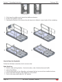
Section 8 - Transport and Lifting Instructions. . . . . . . . . . 26
Transport and Lifting Instructions . . . . . . . . . . . . . . . . 26
Securing to Truck or Trailer for Transit. . . . . . . . . . . . . . . 27
Lifting Instructions . . . . . . . . . . . . . . . . . . . . 28
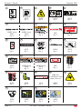
Section 9 - Decals . . . . . . . . . . . . . . . . . 29
RT Machine Decal Locations . . . . . . . . . . . . . . . . . 29
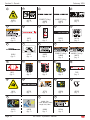
ERT Machine Decal Locations . . . . . . . . . . . . . . . . 32

Page 1 69 Series - Operator’s Manual
February 2019
Introduction
This Operator’s Manual has been designed to provide you, the owner, user or operator, with the
instructions and operating procedures essential to properly and safely operate your MEC Aerial Work
Platform for positioning personnel, along with their necessary tools and materials, to overhead work
locations.
This Operator's Manual and other manuals provided by MEC on the
machine must be read and understood prior to operating your MEC Aerial
Work Platform. The operator should not accept operating responsibility
until he/she has read and understands the operator’s manual as well as
having operated the MEC Aerial Work Platform under supervision of an
authorized, trained and qualified operator.
It is essential that the operator of the aerial work platform is not alone at
the workplace during operation.
Modifications of this machine from the original design and specifications
without written permission from MEC are strictly forbidden. A
modification may compromise the safety of the machine, subjecting the
platform occupants and personal around the machine to serious injury or
death.
Your MEC Aerial Work Platform has been designed, built, and tested to provide safe, dependable
service. Only authorized, trained and qualified personnel shall be allowed to operate or service the
machine.
MEC, as manufacturer, has no direct control over machine application and operation. Proper safety
practices are the responsibility of the owner, user and operator.
If there is a question on application and/or operation contact:
1401 S. Madera Avenue, Kerman, CA 93630 USA
Toll Free: 1 - 877 - 632 - 5438
Phone: 1 - 559 - 842 - 1500
Fax: 1 - 559 - 842 - 1520
www.MECawp.com
MEC Aerial Work Platforms
Section 1 - Introduction

Page 2 69 Series - Operator’s Manual
February 2019
Safety
DO NOT operate this machine until you have read and understood this manual, have
performed the Workplace Inspection, Pre-Start Inspection and Routine Maintenance, and have
completed all the test operations detailed in the Operating Instructions section.
Failure to read, understand and follow all safety rules, warnings, and instructions could result in
serious injury or death. For your safety and the safety of those around you, you must operate your
machine as instructed in this manual.
MEC designs aerial work platforms to safely and reliably position personnel, along with their
necessary tools and materials, at overhead work locations. The owner/user/operator of the machine
should not accept responsibility for the operation of the machine unless properly trained.
ANSI and other applicable standards identify requirements of all parties who may be involved with
self-propelled elevating work platforms. The ANSI/SIA A92.6-2006 Manual of Responsibilities is
considered a part of this machine and can be found in the manual compartment, located at the
platform control station. To ensure safe use of machine, inspections and training specified in ANSI/SIA
A92.6-2006 must be performed at designated intervals as prescribed.
This product can expose you to chemicals known to the State of California
to cause cancer and birth defects or other reproductive harm. For more
information go to www.p65warnings.ca.gov.
Section 2 - Safety
Safety

Page 3 69 Series - Operator’s Manual
February 2019Section 2 - Safety
Safety Alert Symbols & Fall Protection
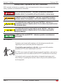
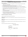
MEC manuals and decals use symbols, colors and signal words to help you recognize important
safety, operation and maintenance information.
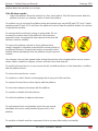
RED and the word DANGER – Indicates an imminently hazardous
situation which, if not avoided, will result in death or serious injury.
ORANGE and the word WARNING – Indicates a potentially hazardous
situation which, if not avoided, could result in death or serious injury.
YELLOW with alert symbol and the word CAUTION – Indicates a
potentially hazardous situation which, if not avoided, may result in minor
or moderate injury.
YELLOW without alert symbol and the word CAUTION – Indicates a
potentially hazardous situation which, if not avoided, may result in
property damage.
GREEN and the word NOTICE – Indicates operation or maintenance
information.
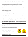
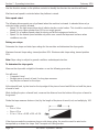
Fall Protection
ART_4713
Operators must comply with employer, job site and governmental rules
regarding the use of personal protective equipment.
If required by your employer or job site, use personal fall protection
equipment (PFPE) when operating this machine.
All PFPE must comply with applicable governmental regulations, and must be
inspected and used in accordance with the PFPE manufacturer’s instructions.
Fall restraint must be properly attached to a designated anchorage point
when driving or operating the machine. Attach only one fall restraint to each
anchorage point.

Page 4 69 Series - Operator’s Manual
February 2019
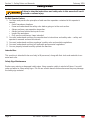
Safety Rules
Failure to obey the instructions and safety rules in this manual will result
in death or serious injury.
Do Not Operate Unless:
You learn and practice the principles of safe machine operation contained in this operator’s
manual.
Avoid hazardous situations.
Know and understand the safety rules before going on to the next section.
Always perform a pre-operation inspection.
Always perform function tests prior to use.
Inspect the workplace.
Only use the machine as it was intended.
You read, understand and obey the manufacturer’s instructions and safety rules— safety and
operator’s manuals and machine decals.
You read, understand and obey employer’s safety rules and worksite regulations.
You read, understand and obey all applicable governmental regulations.
You are properly trained to safely operate the machine.
Intended Use
This machine is intended to be used only to lift personnel, along with their tools and materials to an
aerial work site.
Safety Sign Maintenance
Replace any missing or damaged safety signs. Keep operator safety in mind at all times. Use mild
soap and water to clean safety signs. Do not use solvent-based cleaners because they may damage
the safety sign material.
1.
•
•
•
•
•
•
2.
3.
4.
5.
Section 3 - Safety Rules and Hazards
Safety Rules

Page 5 69 Series - Operator’s Manual
February 2019Section 3 - Safety Rules and Hazards
Safety and Hazards
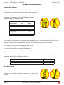
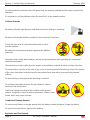
Electrocution Hazards
This machine is not electrically insulated and will not provide
protection from contact with or proximity to electrical current.
Maintain safe distances from electrical power lines and
apparatus in accordance with applicable governmental
regulations and the following chart.
Voltage Minimum Safe Approach Distance
Phase to Phase Feet Meters
0 to 300V Avoid Contact
300V to 50kV 10 3.05
50kV to 200kV 15 4.60
200kV to 350kV 20 6.10
350kV to 500kV 25 7.62
500kV to 750kV 35 10.67
750kV to 1000kV 45 13.72
Allow for platform movement, electrical line sway or sag and beware of strong or gusty winds.
Keep away from the machine if it contacts energized power lines. Personnel on the ground or in the
platform must not touch or operate the machine until energized power lines are shut off.
Do not operate the machine during lightning or storms.
Do not use the machine as a ground for welding.
Tip-over Hazards
Occupants, equipment and materials must not exceed the maximum platform capacity or the
maximum capacity of the platform extension.
Maximum capacity 3369 4069
Platform allowable maximum load 1000 lb 454 kg 800 lb 363 kg
Extension deck allowable maximum load 300 lb 136 kg 300 lb 136 kg
Work Area Safety
Do not raise the platform unless the machine is on a firm, level
surface.

Page 6 69 Series - Operator’s Manual
February 2019Section 3 - Safety Rules and Hazards
Do not depend on the tilt alarm as a level indicator. The tilt alarm sounds on the chassis and in the
platform when the machine is on a slope.
If the tilt alarm sounds:
Lower the platform. Move the machine to a firm, level surface. If the tilt alarm sounds when the
platform is raised, use extreme caution to lower the platform.
For outdoor use, do not raise the platform when wind speeds may exceed 28 mph (12.5 m/s). If wind
speeds exceed 28 mph (12.5 m/s) when the platform is raised, lower the platform and do not continue
to operate the machine.
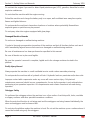
Do not operate the machine in strong or gusty winds. Do not
increase the surface area of the platform or the load when
exposed to wind. Increasing the area exposed to the wind will
decrease machine stability.
Do not use the platform controls to free a platform that is
caught, snagged or otherwise prevented from normal motion by
an adjacent structure. All personnel must be removed from the
platform before attempting to free the platform using the ground
controls.
Use extreme care and slow speeds while driving the machine in the stowed position across uneven
terrain, debris, unstable or slippery surfaces and near holes and drop-offs.
Do not drive the machine on or near uneven terrain, unstable surfaces or other hazardous conditions
with the platform raised.
Do not use the machine as a crane.
Do not place or attach fixed or overhanging loads to any part of this machine.
Do not push the machine or other objects with the platform.
Do not contact adjacent structures with the platform.
Do not alter or disable the limit switches.
Do not tie the platform to adjacent structures.
Do not transport tools and materials unless they are evenly
distributed and can be safely handled by person(s) in the
platform.
Do not alter or disable machine components that in any way affect safety and stability.
•

Page 7 69 Series - Operator’s Manual
February 2019Section 3 - Safety Rules and Hazards
Do not replace items critical to machine stability with items of different weight or specification.
Do not modify or alter an aerial work platform without prior written permission from the manufacturer.
Do not place ladders or scaffolds in the platform or against any part of this machine.
Do not use the machine on a moving or mobile surface or vehicle.
Be sure all tires are in good condition, air-filled tires are properly inflated and lug nuts are properly
tightened.
Crushing Hazards
Keep hands and limbs out of scissors.
Keep hands clear when folding rails.
Use common sense and planning when operating the machine with the controller from the ground.
Maintain safe distances between the operator, the machine and fixed objects.
Maintain a firm grasp on the platform rail when removing the rail pins. Do not allow the platform guard
rails to fall.
Operation on Slopes Hazards
Do not drive the machine on a slope that exceeds the slope and side slope rating of the machine.
Slope rating applies to machines only in the stowed position.
Model Maximum forward slope rating stowed position Maximum side slope rating stowed position
3369 40% 10%
4069 40% 10%
Note:Slope rating is subject to ground conditions and adequate traction.
Fall Hazards
The guard rail system provides fall protection. The platform contains multiple lanyard anchorage
points. Attach only one (1) lanyard per lanyard anchorage point.
Do not sit, stand or climb on the platform guard rails. Maintain a
firm footing on the platform floor at all times.
Do not climb down from the platform when raised.
Keep the platform floor clear of debris.

Page 8 69 Series - Operator’s Manual
February 2019Section 3 - Safety Rules and Hazards
Close the entry gate before operating.
Do not operate the machine unless the guard rails are properly installed and the entry is secured for
operation.
Do not enter or exit the platform unless the machine is in the stowed position.
Collision Hazards
Be aware of limited sight distance and blind spots when driving or operating.
Be aware of extended platform position(s) when moving the machine.
Check the work area for overhead obstructions or other
possible hazards.
Be aware of crushing hazards when grasping the platform
guard rail.
Operators must comply with employer, job site and governmental rules regarding use of personal
protective equipment.
Observe and use color-coded direction arrows on the platform controls for drive and steer functions.
Do not operate a machine in the path of any crane or moving overhead machinery unless the controls
of the crane have been locked out and/or precautions have been taken to prevent any potential
collision.
No stunt driving or horseplay while operating a machine.
Do not lower the platform unless the area below is clear of
personnel and obstructions.
Limit travel speed according to the condition of the ground
surface, congestion, slope, location of personnel, and any other
factors which may cause collision.
Component Damage Hazards
Do not use any battery or charger greater than the battery related voltage to charge the battery.
Do not use the machine as a ground for welding.
Explosion and Fire Hazards

Page 9 69 Series - Operator’s Manual
February 2019Section 3 - Safety Rules and Hazards
Do not start the engine if you smell or detect liquid petroleum gas (LPG), gasoline, diesel fuel or other
explosive substances.
Do not refuel the machine with the engine running.
Refuel the machine and charge the battery only in an open, well-ventilated area away from sparks,
flames and lighted tobacco.
Do not operate the machine in hazardous locations or locations where potentially flammable or
explosive gases or particles may be present.
Do not spray ether into engines equipped with glow plugs.
Damaged Machine Hazards
Do not use a damaged or malfunctioning machine.
Conduct a thorough pre-operation inspection of the machine and test all functions before each work
shift. Immediately tag and remove from service a damaged or malfunctioning machine.
Be sure all maintenance has been performed as specified in this manual.
Be sure all decals are in place and legible.
Be sure the operator’s manual is complete, legible and in the storage container located in the
platform.
Bodily Injury Hazard
Always operate the machine in a well-ventilated area to avoid carbon monoxide poisoning.
Do not operate the machine with a hydraulic oil leak. A hydraulic leak can penetrate and/or burn skin.
Improper contact with components under any cover will cause serious injury. Only trained
maintenance personnel should access compartments. Access by the operator is only advised when
performing a pre-operation inspection. All compartments must remain closed and secured during
operation.
Outrigger Safety
Do not lower the outriggers unless the machine is on a firm surface. Avoid drop-offs, holes, unstable
or slippery surfaces and other possible hazardous conditions.
When the auto level function is not being used and the outriggers are being lowered individually, the
steer-end outriggers must be lowered first.
Do not raise the platform unless the machine is level. Do not set the machine up on a surface where it
cannot be leveled using only the outriggers.

Page 10 69 Series - Operator’s Manual
February 2019Section 3 - Safety Rules and Hazards
Do not raise the platform unless all four outriggers are properly lowered, the footpads are in firm
contact with the ground and the machine is level.
Do not adjust the outriggers while the platform is raised.
Do not drive while the outriggers are lowered.
Battery Safety
Burn Hazard
Batteries contain acid. Always wear protective clothing and eye
wear when working with batteries.
Avoid spilling or contacting battery acid. Neutralize battery acid
spills with baking soda and water.
Explosion Hazard
Keep sparks, flames and lighted tobacco away from batteries.
Batteries emit explosive gas.
Electrocution/ Hazard
Avoid contact with electrical terminals.
Lockout after Each Use
Select a safe parking location - firm level surface, clear of obstruction and traffic.
Lower the platform.
Turn the key switch to the off position and remove the key to secure from unauthorized use.
Push in the red Emergency Stop buttons to “off” position.
Push in the main power switch to “off” position
1.
2.
3.
4.
5.

Page 11 69 Series - Operator’s Manual
February 2019
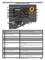
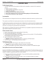
Ground Control Panel
1
11
2
14
12
13
3
4
5
10
6
7
8
9
Control Description
1 Platform Up Button Press this button and the platform will lift.
2 Display Diagnostic readout
3 Engine Idle Select Button
Press this button to select the engine idle setting. Light on
indicates high idle is selected. Light off indicates low idle is
selected.
4 Overload Indicator Light Light on indicates when platform is overloaded (If fitted).
5 Engine Start Button Press this button to start the engine.
6 Engine Glow Plug Button Press and hold this button to preheat engine.
7 Hour Meter
The hour meter displays the number of hours the machine has
operated.
8 Key Switch
Turn the key switch to the platform position and the platform
controls will operate.
Turn the key switch to the off position and the machine will be off.
Turn the key switch to the base position and the ground controls
will operate.
9 Circuit Breaker Circuit breaker
10 Platform Down Button Press this button and the platform will lower
11 Lift Function Enable Button
Press and hold this button along with the Platform Up Button or
the Platform Down Button.
12 Emergency Lowering Down Button Press this button and the platform will lower
13 Emergency Lowering Down Enable Button Press this button to activate the Emergency down function.
14 Red Emergency Stop Button
Push in the red Emergency Stop button to the off position to stop
all functions. Turn the red Emergency Stop button clockwise to
the on position to operate the machine.
Ground Control Panel
Section 4 - Control Panel

Page 12 69 Series - Operator’s Manual
February 2019Section 4 - Control Panel
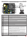
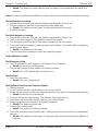
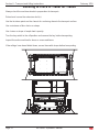
Platform Control Panel
SPEED
AC
3
2
1
2
9
1
13
3
5
6
7
7
7
10
12
11
14
16
15
8
4
ART_4729
Function
Enable
Switch
Control
Handle
Control Description
1 Red Emergency Stop Button
Push in the red Emergency Stop button to the off position to stop all functions. Pull out the red
Emergency Stop button to the on position to operate the machine.
2 Drive Function Select Button Press this button to activate the drive function. The indicator light will turn on.
3
Generator Select Button (If
Equipped)
Press this button to turn the generator on. Indicator light will be on. Press the button again to
turn the generator off.
4 Speed 3 Fastest speed suitable only when on a smooth flat improved surfaces when conditions are safe.
5 Horn Button Press this button and the horn will sound. Release the button and the horn will stop.
6 Speed 1
High torque drive which initiates traction control valves and should be used when driving on any
slopes greater than 10% or over a rough surface.
7 Outrigger Function Button Press this button to activate the represented individual outrigger up/down function.
8 Outrigger Auto Level Button Press this button to activate the auto level function.
9 Engine Glow Plug Button Press and hold this button to preheat engine.
10 LED Readout Screen Diagnostic readout.
11 Engine Start Button Press this button to start the engine.
12 Speed 2 Medium speed suited for driving on flat but unimproved surfaces.
13 Lift Function Select Button Press this button to activate the lift function. The indicator light will turn on.
14 Proportional Control Handle
You must first select either Lift or Drive or Outrigger to activate selected function:
Lift function: Press and hold the function enable switch to enable the lift function on the
platform control handle. Pull the control handle in the direction of upwards and the platform will
raise. Move the control handle in the direction of downwards and the platform will lower. The
descent alarm should sound while the platform is lowering.
Drive function: Press and hold the function enable switch to enable the drive function on the
platform control handle. Move the control handle in the direction indicated by the blue arrow on
the control panel and the machine will move in the direction that the blue arrow points. Move
the control handle in the direction indicated by the yellow arrow on the control panel and the
machine will move in the direction that the yellow arrow points.
Outrigger extendable / retractable function: Press and hold the function enable switch to
enable the Outrigger extend/ retract function on the platform control handle. Move the control
handle in the direction indicated by the yellow arrow and the outrigger will extend. Move the
control handle in the direction indicated by the blue arrow and the outrigger will retract.
15 Thumb Rocker Switch
Press the thumb rocker switch in a direction to activate steer function according to the blue and
yellow steer arrows.
16 Function Enable Switch Press and hold the function enable switch to enable the drive/lift function.

Page 13 69 Series - Operator’s Manual
February 2019
Pre-Operation Inspection
Do Not Operate Unless:
You learn and practice the principles of safe machine operation contained in this operator’s
manual.
Avoid hazardous situations.
Always perform a pre-operation inspection.
Know and understand the pre-operation inspection before going on to the next
section.
Inspect the workplace.
Always perform function tests prior to use.
Only use the machine as it was intended.
Fundamentals
It is the responsibility of the operator to perform a pre-operation inspection and routine maintenance.
The pre-operation inspection is a visual inspection performed by the operator prior to each work shift.
The inspection is designed to discover if anything is apparently wrong with a machine before the
operator performs the function tests.
The pre-operation inspection also serves to determine if routine maintenance procedures are
required. Only routine maintenance items specified in this manual may be performed by the operator.
Refer to the list on the next page and check each of the items.
If damage or any unauthorized variation from factory delivered condition is discovered, the machine
must be tagged and removed from service.
Repairs to the machine may only be made by a qualified service technician, according to the
manufacturer’s specifications. After repairs are completed, the operator must perform a pre-operation
inspection again before going on to the function tests.
Scheduled maintenance inspections shall be performed by qualified service technicians, according to
the manufacturer’s specifications and the requirements listed in this manual.
•
1.
2.
3.
4.
5.
6.
Pre-Operation Inspection
Section 5 - Pre-Operation & Workplace Inspection

Page 14 69 Series - Operator’s Manual
February 2019Section 5 - Pre-Operation & Workplace Inspection
Pre-Operation Inspection Report
Be sure that the operator’s, safety and responsibilities manuals are complete, legible and in the storage
container located in the platform.
Be sure that all decals are legible and in place. See Decals section.
Check for engine oil leaks and proper oil level. Add oil if needed. See Maintenance section.
Check for hydraulic oil leaks and proper oil level. Add oil if needed. See Maintenance section.
Check for engine coolant leaks and proper level of coolant. Add coolant if needed. See Maintenance section.
Check for battery fluid leaks and proper fluid level. Add distilled water if needed. See Maintenance section.
Check the following components or areas for damage, improperly installed or missing parts and
unauthorized modifications:
Electrical components, wiring and electrical cables
Hydraulic hoses, fittings, cylinders and manifolds
Fuel and hydraulic tanks
Drive motors
Wear pads
Tires and wheels
Engine and related components
Limit switches, alarms and horn
Nuts, bolts and other fasteners
Platform overload components
Platform entry gate
Brake release components
Beacon (if equipped)
Safety arm
Platform extension(s)
Scissor pins and retaining fasteners
Platform control handle
Generator (if equipped)
Outrigger housings and footpads (if equipped)
Check entire machine for:
Cracks in welds or structural components
Dents or damage to machine
Excessive rust, corrosion or oxidation
Be sure that all structural and other critical components are present and all associated fasteners and pins are
in place and properly tightened
Be sure guardrails are installed and bolts are fastened.
Note:If the platform must be raised to inspect the machine, make sure the safety arm is in place. See
Operating Instructions section.

Page 15 69 Series - Operator’s Manual
February 2019Section 5 - Pre-Operation & Workplace Inspection
Workplace Inspection
Do Not Operate Unless:
You learn and practice the principles of safe machine operation contained in this operator’s
manual.
Avoid hazardous situations.
Always perform a pre-operation inspection.
Inspect the workplace.
Know and understand the workplace inspection before going on to the next section.
Always perform function tests prior to use.
Only use the machine as it was intended.
Fundamentals
The workplace inspection helps the operator determine if the workplace is suitable for safe machine
operation. It should be performed by the operator prior to moving the machine to the workplace.
It is the operator’s responsibility to read and remember the workplace hazards, then watch for and
avoid them while moving, setting up and operating the machine.
Workplace Inspection
Be aware of and avoid the following hazardous situations:
Drop-offs or holes
Bumps, floor obstructions or debris
Sloped surfaces
Unstable or slippery surfaces
Overhead obstructions and high voltage conductors
Hazardous locations
Inadequate surface support to withstand all load forces imposed by the machine
Wind and weather conditions
The presence of unauthorized personnel
Other possible unsafe conditions
•
1.
2.
3.
4.
5.
6.
•
•
•
•
•
•
•
•
•
•

Page 16 69 Series - Operator’s Manual
February 2019
Function Tests
Do Not Operate Unless:
You learn and practice the principles of safe machine operation contained in this operator’s
manual.
Avoid hazardous situations.
Always perform a pre-operation inspection.
Inspect the workplace.
Always perform function tests prior to use.
Know and understand the function tests before going on to the next section.
Only use the machine as it was intended.
Fundamentals
The function tests are designed to discover any malfunctions before the machine is put into service.
The operator must follow the step-by-step instructions to test all machine functions.
A malfunctioning machine must never be used. If malfunctions are discovered, the machine must be
tagged and removed from service. Repairs to the machine may only be made by a qualified service
technician, according to the manufacturer’s specifications.
After repairs are completed, the operator must perform a pre-operation inspection and function tests
again before putting the machine into service.
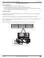
At the Ground Controls
Select a test area that is firm, level and free of obstruction.
Pull out main power switch to “on” position.
Turn the ground red Emergency Stop button clockwise to the on position. Pull out the platform
red Emergency Stop button to the on position.
Turn the key switch to ground control.
Observe the display on the ground controls.
Result: The display readout will come on and display SYSTEM READY.
Start the engine. See Operating Instructions section.
Test Emergency Stop
Push in the ground red Emergency Stop button to the off position.
Result: The engine should turn off and no functions should operate.
Turn the red Emergency Stop button clockwise to the on position. And restart the engine.
Test Up/Down Functions and Function Enable
A buzzer with different sound frequency is controlled in control system. The descent alarm sounds at
60 beeps per minute. The alarm that goes off when the machine is not level sounds at 180 beeps per
minute. An optional automotive-style horn is also available.
Do not press the lift function enable button. Press and hold the platform up/down button.
Result: No function should operate.
Press and hold the Lift function enable button. Press and hold the platform up button.
Result: The platform should rise.
•
1.
2.
3.
4.
5.
6.
1.
2.
3.
4.
5.
•
6.
1.
•
2.
1.
•
2.
•
Function Tests
Section 6 - Function Tests

Page 17 69 Series - Operator’s Manual
February 2019Section 6 - Function Tests
Press and hold the lift function enable button. Press and hold the platform down button.
Result: The platform should lower the descent alarm should sound while the platform is
lowering.
Note:Be sure the area below the platform is clear of personnel and obstructions before continuing.
Test the Auxiliary Lowering
Activate the up function and raise the platform approximately 3 feet (1 m).
Pull the emergency lowering knob located the entry ladder end.
Result: The platform should lower. The descent alarm will not sound.
Restart the engine.
Test the Emergency Lowering
Activate the up function and raise the platform approximately 3 feet (1 m).
Push in the red Emergency Stop button to shut off the engine.
Turn the ground red Emergency Stop button clockwise to the on position.
Press and hold the emergency lowering down enable button. Press and hold the emergency
lowering down button.
Result: The platform should lower.
Turn the key switch to platform control and restart the engine.
At the Platform Controls
Test Emergency Stop
Push in the platform red Emergency Stop button to the off position.
Result: No functions should operate.
Pull the red Emergency Stop button out to the on position.
Result: The LED indicator light should come on.
Test the Horn
Push the horn button.
Result: The horn should sound.
Test Up/Down Functions and Function Enable
Start the engine.
Do not hold the function enable switch on the control handle.
Slowly pull the control handle in the upwards direction, then push in the downwards direction.
Result: No functions should operate.
Press the lift function select button. The indicator light should turn on.
Press and hold the function enable switch on the control handle.
Slowly move the control handle in the upwards direction.
Result: The platform should raise.
Release the control handle.
Result: The platform should stop raising.
Press and hold the function enable switch. Slowly push the control handle in the downwards
direction.
Result: The platform should lower. The descent alarm should sound while the platform is
lowering.
3.
•
1.
2.
•
3.
1.
2.
3.
4.
•
5.
1.
•
2.
•
1.
•
1.
2.
3.
•
4.
5.
6.
•
7.
•
8.
•
Page is loading ...
Page is loading ...
Page is loading ...
Page is loading ...
Page is loading ...
Page is loading ...
Page is loading ...
Page is loading ...
Page is loading ...
Page is loading ...
Page is loading ...
Page is loading ...
Page is loading ...
Page is loading ...
Page is loading ...
Page is loading ...
Page is loading ...
Page is loading ...
Page is loading ...
Page is loading ...
-
 1
1
-
 2
2
-
 3
3
-
 4
4
-
 5
5
-
 6
6
-
 7
7
-
 8
8
-
 9
9
-
 10
10
-
 11
11
-
 12
12
-
 13
13
-
 14
14
-
 15
15
-
 16
16
-
 17
17
-
 18
18
-
 19
19
-
 20
20
-
 21
21
-
 22
22
-
 23
23
-
 24
24
-
 25
25
-
 26
26
-
 27
27
-
 28
28
-
 29
29
-
 30
30
-
 31
31
-
 32
32
-
 33
33
-
 34
34
-
 35
35
-
 36
36
-
 37
37
-
 38
38
-
 39
39
-
 40
40


Mec 3369ERT - A92.6 Operating instructions
- Category
- Utility Vehicle
- Type
- Operating instructions
- This manual is also suitable for
Ask a question and I''ll find the answer in the document
Finding information in a document is now easier with AI
Related papers
-
Mec 3369ERT - A92.6 Operating instructions
-
-
-
-
-
-
-
-
-
Other documents
-
 DINGLI JCPT0407 Operators Manual With Maintenance Information
-
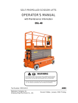 Ballymore DSL-40 User manual
-
 Sontax 73535 User manual
-
Terex Genie GS-4069BE User manual
-
-
Genie GS-5390 User manual
-
PRO-SERIES 803099 User manual
-
-
 LGMG AS0607 User manual
-


