Page is loading ...

1 “Translation of the original instruction”
Instant UpRight
Self-propelled Scissor Lift MX & X series
Service and Maintenance Manual

2 “Translation of the original instruction”
Note: The Company’s products are in continuous improvement, diagrams are
not modified generally unless the product has significant changes. For any
queries or discrepancies refer to Upright or appointed agent.
Dear Clients:
Thank you for purchasing this quality product!
Your new access equipment is the result of an innovative
approach and the pursuit of quality. It has been designed to be
functional, safe, comfortable and durable. It has style with
excellent operational features.
When your machine requires maintenance, only the genuine
spare parts should be used as supplied by Upright in order to
ensure safety and reliability.
Before operating, please read and understand this manual
thoroughly!
!

3 “Translation of the original instruction”
Table of content
Brief Introduction
Essentials............................................................
......6
Safety Rules
General Safety Rules....................................................
......7
Specification
Hydraulic specifications........................................................
......14
Hydraulic joint thread torque................................................
......15
Regular maintenance procedures
Check table A program
A-1 Check the operating manual and safety manual....................................
......23
A-2 Check the logo and label............................................
......23
A-3 Perform pre-operation check............................................
......24
A-4 Perform functional test..............................................
......24
A-5 Check the hydraulic oil level............................................
......25
A-6 Check for fuel leakage..............................................
.....
.25
A-7 Check the tire pressure..............................................
......26
Check table B program
B-1 Check the battery................................................
......27
B-2 Check the electrical wiring..............................................
......29
B-3 Check tire, wheel and groove nut torque..............................
......30
B-4 Test emergency stop..............................................
......30
B-5 Test the key switch..............................................
......31
B-6 Test drive brakes............................................
......31
B-7 Test drive speed - stowed position....................................
......32
B-8 Test drive speed - raised position....................................
......32
B-9 Check the electrical contactor............................................
......33
B-10 Perform hydraulic oil analysis............................................
......33

4 “Translation of the original instruction”
B-11 Check the oil level in the drive hub......................................
......34
B-12 Replace the hydraulic tank return filter....................................
......34
B-13 Check that the brake structure is correct..........................................
......35
Check table C program
C-1 Test platform overload pressure sensor and platform height sensor (if
equipped)........
......36
Check table D program
D-1 Check the chassis slider and the platform slider....................................
......39
D-2 Replace the hydraulic filter............................................
......39
D-3 Replace the wheel oil............................................
......40
D-4 Test function pump................................................
......41
Check table E program
E-1 Test or replace hydraulic oil..........................................
......42
E-2 Apply grease to steering shaft and wheel bearings................................
......43
Repair procedures
Platform controller
1-1 Method of removing the platform controller circuit board ................................
......46
1-2 Method of removing the handle........................................
......47
1-3 Method of removing the platform control alarm..................................
......47
1-4 Method of removing the platform controller emergency stop
button..........................
......48
Platform components
2-1 Method of removing the platform............................................
......49
2-2 Method of removing the platform extension board....................................
......50
Scissor arm components
3-1 Method of removing scissor arm parts (take 80W as an
example)............................
......52
3-1 Method of removing scissor arm parts (take 100W as an
example)...........................
......56
3-3 Method of replacing the pad............................................
......58
3-3 Lifting cylinder..................................................
......59
Chassis components
4-1 Hydraulic pump....................................................
......61
4-2 Hydraulic tank..................................................
......62

5 “Translation of the original instruction”
4-3 Method of removing the steering wheel seat parts....................................
......63
4-4 Method of removing the motor............................................
......64
4-5 Method of removing the steering cylinder........................................
......64
4-6 Method of removing the rod............................................
......65
Fault code
B system fault code ...................................................
......68
Simplified diagram
Electrical diagram
Electrical schematic of electric drive A system............................................
......74
Electrical schematic of electric drive B system............................................
......75
Electrical schematic of hydraulic drive A system............................................
......76
Schematic of electrical components of hydraulic drive A
system........................................
......77
High current wiring diagram of hydraulic drive A system......................................
......78
Wiring diagram of hydraulic drive A system............................................
......79
Diagram of descend line, raised switch, 2m limit six core line of hydraulic drive A
system.................
......80
Connection diagram of descend line, raised switch, 2m limit six core line of hydraulic
drive A system.................
......81
Schematic diagram of valve group connection line of lower control box to controller of
hydraulic drive A system......................
......82
Wiring diagram of valve group connection line of lower control box to controller of
hydraulic drive A system......................
......83
Upper control six core wire of hydraulic drive A system............................................
......84
Internal wiring diagram of base control box of hydraulic drive A
system
...................................
......85
Internal wiring diagram of upper control box of hydraulic drive A
system
...................................
......86
Electrical schematic of hydraulic drive B system............................................
......87
Schematic of electrical components of hydraulic drive B
system........................................
......88
High current wiring diagram of hydraulic drive B system......................................
......89
Wiring diagram of hydraulic drive B system............................................
......90
Upper control six core wire of hydraulic drive B system............................................
....
..91
Wiring diagram of hydraulic drive B system..........................................
......92
Schematic diagram hydraulic drive B system..........................................
......93

6 “Translation of the original instruction”
Internal wiring diagram of base control box of hydraulic drive B
system......................................
......94
Hydraulic diagram
Hydraulic schematic of X-W Series
.........................................
......95
Essentials
Thank you for choosing and using our machines. We pay attention to the safety of users,
which by our endeavors we attempt to achieve it. We believe that as a user and operator
of our equipment, and you comply with the following requirements, the use of equipment
in the correct manner will ensure a greater level of safety: therefore it is essential that the
user
1. Is Compliant with user rules, workplace rules and government rules.
2. Reads, understands and complies with the instructions contained in this manual and
other manuals accompanying the machine.
3. Performs good safety practices by convention.
4. is Trained, Certified and Authorised to use the machine under the guidance of
experienced and knowledgeable supervisors.
Please contact us if there is content that is ambiguous in this manual or suggestions on
how we might improve the content to your satisfaction.
Web
:
www.instantupright.com

7 “Translation of the original instruction”
1. Safety Rules
Dangerous
Failure to follow the instructions and safety rules in this manual may result in
death or serious injury.
The machine maintenance work shall not be carried out unless the following conditions are
met:
Maintenance personnel for this machine are trained and qualified.
Read, understand and observe:
- Manufacturer's instructions and safety rules
- Employer safety rules and workplace regulations
- And any applicable government regulations
the Workshop that has the correct tools and working environment to carry out the necessary repairs.

8 “Translation of the original instruction”
1.1 Safety Rules
1.1.1Personnel Safety
Any person working on or around the
machine, beware of all known dangerous
operating safety hazards. Personnel
safety and continuous safe operation of
the machine should be the top priority.
Read each procedure carefully.
The meanings of the symbols
used in this manual and on
the machine are as follows:
Safety warning signs - used
to indicate potential
personal injury. Observe all
safety tips on the mark to
avoid possible injury or
death.
Indicates the emergency
hazard condition, if not
avoided, could result in
death or serious injury.
Indicates the potential
emergency hazard
condition, if not
avoided, could result in
death or serious injury.
Indicates the potential
emergency hazard
condition, if not
avoided, could result in minor or
moderate personal injury.
Note Indicates the potential
emergency hazard condition, if not
avoided, could result in property
damage.
If necessary, be sure to wear
protective glasses and wear
protective clothing.
When Lifting or loading the
SWL when the parts are
moving, parts that are free to
swing or are not fixed, may
cause a risk of injury. Always put on
protective shoes and clothing while
working.

9 “Translation of the original instruction”
1.1.2 Work Place Safety
Be sure to keep flame and lit
lighted cigarettes away from
flammable substances such as
battery gas and engine fuel.
Place an approved fire extinguisher in an
easily accessible area.
Be sure to maintain all the
tools and work areas for use.
Keep the working surface clean
and prevent debris from
entering the machine parts.
Be sure that all forklifts,
cranes and other lifting or
supporting equipment have
sufficient support strength and safety
stability for the objects they lift. Use in
good condition and have enough
strength for chains and belts.
Be sure to ensure that
disposable fasteners (ie, cotter
and self-locking nuts) can not
be reused. The second use of
these components may result in failure.
Be sure to correctly handle
waste oil or other liquids. Use
approved containers. To ensure
environmental safety.
Be sure to keep the
Workshops well ventilated
and bright.

10 “Translation of the original instruction”
2
.
Hydraulic Specifications
Function Pump
Type: Gear pump
Displacement
Per rotation
4cc
Velocity at 3000rpm 12L/min
Functional Manifold
System safety valve pressure
240bar
Raise safety valve pressure 190bar
Steering relief valve pressure
120bar
Steering flow regulator 3.5L/min

11 “Translation of the original instruction”
2.3 Hydraulic Joint Thread Torque
Metric O-ring flat seal torque, 74° metric torque

12 “Translation of the original instruction”
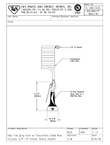
2.4 Hydraulic Hoses and Fittings Installation Procedures
1.Replace the "O" ring.
2.When the seal leaks, the "O" ring must be replaced. The "O" ring shall not be reused if the torque at
the joint or hose connector exceeds the tightening torque/force of the hand.
3.Apply a layer of oil to the "O" ring before installation.
4.Ensure that the cross-section seal "O" is place fitted and positioned correctly.
5.Straighten the pipe and nut joint seal and tighten the nut by hand.
6.In accordance with the above table, tighten the nut and joints according to the established size of
the corresponding torque.
7.Run all the functions of the machine and check the hose and fittings as well as the relevant parts to
ensure no leakage.

13 “Translation of the original instruction”
2.5 Specification
SAE Fastener Torque Chart
Use this Chart only for reference unless otherwise noted in other places in this
manual. *
Dimension Screw thread Class 5 Class 8 A574 High strength black oxidation bolts
Lubricant Dry
Metric Fasteners Torque Chart
Use this Chart only for reference unless otherwise noted in other places in this
manual.

14 “Translation of the original instruction”

15 “Translation of the original instruction”
3. Regular Maintenance Procedures
Please obey:
Maintenance and inspection should be carried
out by trained maintenance and qualified
personnel for this machine.
Perform maintenance inspections daily,
quarterly, semi-annual, annual and every two years
according to the maintenance inspection report.
Caution!
Failure to implement the procedures
specified may result in death, serious injury or
substantial damage to the machine.
Damaged or malfunctioning machines should be
marked immediately and removed from use.
Before operating the machine, repair all damage
and malfunctions of the machine.
Use only Instant UpRight approved replacement
parts.
For machines that are idle for more than 3
months, quarterly checks must be made.
Unless otherwise specified, the following
procedure shall be followed when undertaking any
and all maintenance work.
. Place the machine on a solid horizontal surface
. The platform is in the stowed position
. The key switch is in the OFF position and the key is
unplugged
. The red "emergency stop" button for the ground
and platform controllers is in the OFF position
. The wheel is in a locked state
.
The machine has been disconnected from all
external AC power sources
About this section
This section contains detailed procedures for each
periodic maintenance check. Each program includes
instructions, safety warnings and step-by-step
instructions.
Symbol legend
Safety warning signs - Used to warn of potential
danger of personal injury
Prompts an emergency hazard situation that, if not
avoided, can result in death or serious injury
Prompts an emergency hazard situation that, if not
avoided, could result in minor or moderate personal
injury
Prompts a potentially hazardous situation that, if not
avoided, could result in property damage
Tip :
After completing a series of steps, specific result
may appear
Tip
After completing a series of steps, an error result
appears

16 “Translation of the original instruction”
3.1 Regular Maintenance Procedures
Maintenance Symbol Legend:
Note: This manual uses the following
symbols to help express the relevant
meaning in the instructions. When the
maintenance program appears in front
of one or more symbols, the meaning of
the expression is as follows.
Indicates that the tool is required to
execute this program.
Indicates that the execution of this
program requires new parts.
Indicating that the engine is
overheating and needs to be in cooled.
Indicates that the engine needs to be in
a heated state.
Indicates that this program requires the
attention of authorised service
personnel.
Pre-delivery preparation report
The pre-delivery preparation report
contains a checklist of each type of
periodic inspection. Copy the
preparation report before delivery for
inspection. Save the completed form as
needed.
Maintenance schedule
According to the timetable, there are
five types of maintenance checks that
must be carried out. Daily, quarterly, six
monthly,Yearly and every two years.
Periodic maintenance procedures
section and maintenance inspection
reports are divided into five subsections,
A, B, C, D and E. Please follow the table
below to determine the program
combination for performing periodic
checks.
Check Check table
Every day or every 8 hours A
Every quarter or every 250 hours A+B
Every six months or every 500 hours A+B+C
Every year or every 1000 hours A+B+C+D
Every two years or every 2000 hours A+B+C+D+E
Maintenance Check Report
The maintenance check report contains a list of check items for each type of periodic
inspection.
Copy and maintain check reports for inspection, save the completed forms at least 4
years or save it in accordance with employers, workplaces and government regulations
and requirements.

17 “Translation of the original instruction”
3.2 Basic principle
The implementation of "pre-delivery" is the responsibility of the dealer.
Perform "pre-delivery" inspection before each delivery. The purpose of the inspection is
to find out if there is a significant problem before the machine is put into use.
Damaged or altered machines should not be used. If any damage is found or
non-approved parts fitted from original manufacturer’s parts, the machine should be
removed from service and reported.
According to the manufacturer's regulations, only qualified service technicians can
repair the machine.
In accordance with the requirements set out in the manufacturer's specifications and
duties manual, periodic maintenance inspections should be performed by qualified
service technicians.
3.3 Specification
Use the machine's operating manual.
"Pre-delivery preparation" consists of a pre-operation check, maintenance item, and
functional test.
Use this form to record the results. After completing each part, mark the corresponding
box. Follow the instructions in the operating instructions.
If any of the checks are marked as "N", the machine is deactivated, repaired and
rechecked. After repair, mark the box marked "R".
Legend
Y = Yes, has been completed
N = No, cannot complete
R= R = has been repaired
Note

18 “Translation of the original instruction”
Prepare before delivery Y N R
All Checks before Operating are completed
The maintenance project is completed
Functional testing is completed
Model
Series Number
Date
Machine owner
Inspector (please write in block letters)
Inspector signature
Inspector duties
Inspector’s office

19 “Translation of the original instruction”
4. Maintenance Check Report
Model
Serial number
Date
Machine owner
Inspector (please write in block letters)
Inspector signature
Inspector duties
Inspector's office
Copy this report for use with each check.
Select the appropriate checklist according to the type of inspection.
Every day or every 8 hours
Check: A
Every quarter or every 250 hours
Check: A+B
Every six months or every 500 hours
Check: A+B+C
Every year or every 1000 hours
Check: A+B+C+D
Every two years or every 2000 hours
Check: A+B+C+D+E
After completing each inspection procedure, mark the corresponding box.
Use the step-by-step check program in this section to learn how to check.
If any of the inspections are marked as "N", the machine is marked, repaired and
rechecked and reinspected. After repair, mark the box with "R".
Legend
Y = Yes, acceptable
N = No, stop using

20 “Translation of the original instruction”
Check table A Y N R
A-1 Check the Operating and safety manual/s
A-2 Check the logo and label
A-3 Perform pre-operation check
A-4 Perform Functional test/ check
A-5 Check the hydraulic oil level
A-6 Check for hydraulic oil leak
A-7 Check the tire pressure & nuts torqued
/