Page is loading ...

3/8"-16x4"
Carriage Bolt
Elbow
Air Line
Pal Nut
(flange up)
3/8"
Locknut
3/8" Flat
Washer
3/8"-16x1"
HHCS
3/8"-16x5"
Carriage Bolt
Upper
Bracket
Sleeve
Lower
Bracket
1/2" Flat Washer
1/2" Lock Washer
1/2" HHCS
Box
Clamp
3/8" Flat
Washer
3/8"
Locknut
3/8"
Locknut
Locator
Tab
FORWARD
OUTBOARD
3/8" Flat
Washer
12mm
Hex Nut
BY
MN-299
(03711)
ECN2306
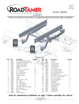
Figure 1
WARNING: DO NOT INFLATE ASSEMBLY WHEN IT IS NOT RESTRICTED. ASSEMBLY MUST BE RESTRICTED BY
SUSPENSION OR OTHER ADEQUATE STRUCTURE. DO NOT INFLATE BEYOND 100 P.S.I. IMPROPER USE OR OVER
INFLATION MAY CAUSE ASSEMBLY TO BURST CAUSING PROPERTY DAMAGE OR SEVERE PERSONAL INJURY.
INSTALLATION INSTRUCTIONS
P/N 59109
NOTE: It may be necessary to move or
modify the exhaust to install this kit.
NOTE: There must be no
less than 3.5” from the
bottom of the frame to the
top of axle to install this kit.
This kit WILLNOTFIT if the
frame has been notched.

Original
Hole
New Hole
5" inboard
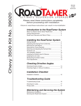
Figure 2
NORMAL RIDE HEIGHT:
Normal ride height (no load) - This is defined as the distance
between the bottom of the bumper and a flat road surface with the
vehicle in “as delivered condition” (without a load, i.e. tool box,
camper, etc.) measurements should be taken before beginning
the installation. The distance from the fender well to the center
point of the hub should be recorded. All of our kits are designed
to be installed and operate at normal ride height.
IMPORTANT:
Your vehicle may be equipped with a rear brake proportioning
valve. Any type of load assist suspension product could affect
brake performance. We recommend that you check with your
dealer before installing this type of product. If your vehicle does
not have a proportioning valve or is equipped with an anti-lock
brake system, no adjustment or modification is required.
1. Jack up rear of vehicle or raise on hoist and remove rear
wheels.
2. Assemble the sleeve onto the upper bracket by installing the
pal nut then tightening to 15 ft-lbs (Figure 1).
3. LOOSELY assemble sleeve onto the lower bracket using the
bolt, lock washer, and flat washer exactly as shown in Figure
1. Leave slightly loose for final adjustment.
4. On some vehicles it will be necessary to relocate the
emergency brake cable on the driver’s side of the vehicle.
This can be accomplished by moving the hanger inboard
approximately 5”. Drill a new hole and re-install using the
same hardware (See Figure 2).
5. LOOSELY attach the locator tab to the lower bracket using a
1” bolt, two flat washers and a lock nut. The tabs are made
for left and right hand side attachment (Figure 1).
6. Set assembly onto axle housing. Check to be sure the
locator tab slides over the existing rear u-bolt. Use the 12mm
hex nut provided to attach the locator tab to the u-bolt (Figure
1).
7. Position the upper bracket on the frame so that it is tight
against the bottom of the frame. Align the upper bracket over
the lower bracket. The lower bracket can be rotated on the
axle housing so the brackets are parallel to one another.
8. Secure the lower bracket to the axle using the 5” carriage
bolts, box clamps, flat washers and lock nuts. Tighten to 20
ft-lbs. Tighten the bolt on the locator tab (Figure 1).
9. Use the upper bracket as a template and mark all four holes
to be drilled. Move the upper bracket aside and drill 3/8”
holes.
CAUTION: DO NOT DRILL HOLES INTO THE FRAME UNTIL
ANY HYDRAULIC LINES, GAS LINE AND ELECTRICAL
WIRES HAVE BEEN MOVED ASIDE ON BOTH SIDES OF
FRAME RAIL.
10. Align the upper bracket holes with the holes in the frame
section and secure to the frame using the 4” carriage bolts,
flat washers and lock nuts and tighten to 20 ft-lbs.(Figure 1).
2
Drill a 17/64” hole
If your vehicle does not have this type of
cable hanger, be sure to check for any
possible interference between the cable
and the air spring. If necessary LOOSELY
tie cable away from the air spring with one
of the provided plastic straps.

Fig.8 MN 190
Air Line to
Bellows
Star
Washer
Vehicle body
or bumper
Rubber Washer
Flat Washer
Heat
Shield
Air Spring
Thermal
Sleeve
11. Install the air fitting into the sleeve , tighten finger
tight plus two turns. Use a 7/16” open end wrench
being careful to tighten on the metal hex nut
only. DO NOT OVER TIGHTEN. This fitting is
precoated with thread sealant.
12. Select a location for the inflation valves in the rear
bumper area or rocker panel flange ensuring that
each valve will be protected and accessible with an
air hose (Figure 4).
13. Use a standard tube cutter, a razor blade, or very
sharp knife to cut the air line in two equal lengths. A
clean square cut will ensure against leaks. Drill
5/16” hole for inflation valve and mount as
illustrated. Rubber washer on outside is for weather
seal (Figure 5).
CAUTION: LEAVE SUFFICIENT AIR LINE SLACK TO
PREVENT ANY STRAIN ON VALVE STEM DURING
NORMAL AXLE MOTIONS.
14. Route air line along frame to desired inflation valve
location (Figure 5). Attach air line to chassis with the
provided plastic straps. It will be necessary to install
a heat shield on the passenger side where the
exhaust pipe runs close to the air spring. You will
also need to use the provided thermal sleeve on
the air line in the vicinity of the exhaust pipe (See
Figure 3).
TO PREVENT AIR LINE FROM MELTING, KEEP IT AT
LEAST TWELVE INCHES FROM EXHAUST SYSTEM.
15. Cut off excess air line squarely. Install the air line
into the fitting. This is a self locking fitting. Push and
slightly turn the cut end of the air line into the fitting
as far as it will go. You will hear/feel a definite “click”
when the air line is seated. Air line should go in
approximately 3/4”. The air line is now installed.
16. Repeat process for right side.
17. VERY IMPORTANT - With the bottom still loose,
inflate the sleeve to approximately 10 p.s.i. By using
the slotted adjustment, align the sleeve so that there
is a symmetrical cushion of air around the lower
base of the sleeve to prevent side load wear (Figure
6). Tighten the lower sleeve mounting bolt to 10
ft/lbs. DO NOT OVER TIGHTEN.
18. Inflate to 30 p.s.i. Check all fittings and valve core
with a soapy water solution for leaks. check once
again to be sure you have proper clearance around
the sleeve. When the sleeve is inflated there must
be 1/2” of clearance all around the sleeve.
Maximum diameter of sleeve is 4.6”.
19. Recheck air pressure after 24 hours. A 2-4 p.s.i.
loss after initial installation is normal. If pressure
has dropped more than 5 lbs. re-test for leaks with
soapy water solution. Please read and follow the
Maintenance and Operating Tips. (Make sure that
the sleeve rolls back down over the piston after
the vehicle is lowered (Figure 6).
Figure 3
Figure 5
3
Option 1
Option 2
Figure 4

MAINTENANCE/OPERATION
MAINTENANCE
1. Check pressure weekly.
2. Always maintain at least 10 p.s.i. air pressure to prevent chafing.
3. If you develop an air leak in the system, use a soapy water solution to check all hose connections and the
inflation valve core before removing sleeve.
OPERATING TIPS
1. Inflate your air springs to 60 p.s.i. before adding the payload. After vehicle is loaded, adjust your air pressure
to level the vehicle and for ride comfort.
2. When you are carrying a payload it will be helpful to increase the tire inflation pressure in proportion to any
overload condition. We recommend a 2 p.s.i. increase above normal (not to exceed tire manufacturer
maximum) for each 100 lbs. total overload on the axle.
NOTE
1. IMPORTANT: For your safety and to prevent possible damage to your vehicle, do not exceed maximum load
recommended by the vehicle manufacturer. Although your air springs are rated at maximum inflation pressure
of 100 p.s.i., this pressure may represent too great of load on some vehicles. Check your vehicle owner’s
manual and do not exceed maximum loads listed for your vehicle.
When inflating your Air Lift sleeves, add pressure in small quantities, checking pressure frequently during
inflation. The sleeves require much less air volume than a tire and therefore inflate much faster.
2. Should it become necessary to raise the vehicle by the frame, make sure the system is at minimum
pressure (10psi) to reduce the tension on suspension/brake components. Check to see that the sleeve
rolls back down over the bottom piston after the vehicle is lowered (Figure 6). If sleeve fails to roll
back down over the piston, add air pressure until sleeve “pops” back over piston (do not exceed 100
p.s.i.).
FAILURE TO MAINTAIN MINIMUM PRESSURE, BOTTOMING OUT, OR OVER
EXTENSION WILL VOID THE WARRANTY
4
MINIMUM AIR PRESSURE
10 P.S.I.
MAXIMUM AIR PRESSURE
100 P.S.I.
Thank you for purchasing Air Lift Products
AIR LIFT COMPANY
P.O. BOX 80167
Lansing, MI 48908-0167
FOR TECHNICAL ASSISTANCE CALL 1-800-248-0892
Caution: DO NOT EXCEED THE VEHICLE MANUFACTURERS MAXIMUM GROSS VEHICLE WEIGHT RATING.
Printed in the USA
FIGURE 6
CORRECT FINISHED
INSTALLATION
(inflated)
NOT CORRECT
MISALIGNED OR UNDER INFLATED
(ok during assembly)
FINISHED INSTALLATION

Product Use Information
Frequently asked questions
Q. Will installing air springs increase the weight ratings of a vehicle?
No. Adding air springs will not change the weight ratings (GAWR, GCWR and/or GVWR) of a vehicle. Exceeding the
GVWR is dangerous and voids the Air Lift warranty.
Q. Is it necessary to keep air in the air springs at all time and how much pressure will they need?
The minimum air pressure should be maintained at all times. The minimum air pressure keeps the air spring in shape,
ensuring that it will move throughout its travel without rubbing or wearing on itself.
Q. Is it necessary to add a compressor system to the air springs?
No. Air pressure can be adjusted with any type of compressor as long as it can produce suffi cient pressure to service
the springs. Even a bicycle tire pump can be used, but it’s a lot of work.
Q. How long should air springs last?
If the air springs are properly installed and maintained they can last indefi nitely.
Q. Will raising the vehicle on a hoist for service work damage the air springs?
No. The vehicle can be lifted on a hoist for short-term service work such as tire rotation or an oil changes. However,
if the vehicle will be on the hoist for a prolonged period of time, support the axle with jack stands in order to take the
tension off of the air springs.
Tuning the air pressure
Pressure determination comes down to three things — level vehicle, ride comfort, and stability.
1. Level vehicle
If the vehicle’s headlights are shining into the trees or the vehicle is leaning to one side, then it is not level (fi g. 1).
Raise the air pressure to correct either of these problems and level the vehicle.
2. Ride comfort
If the vehicle has a rough and harsh ride it may be due to either too much pressure or not enough. Try different
pressures to determine the best ride comfort.
3. Stability
Stability translates into safety and should be the priority, meaning the driver may need to sacrifi ce a perfectly level
and comfortable ride. Stability issues include roll control, bounce, dive during braking and sponginess (fi g. 2). Tuning
out these problems usually requires an increase in pressure.
Continued on pg. 2
fi g . 2
fi g . 1
Bad headlight aim
Level
Unlevel, bottoming out

Thank you for purchasing Air Lift products! For technical support, please call (800) 248-0892.
Air Lift Company • P.O. Box 80167, MI 48908-0167 • (517) 322-2144 • Fax: (517) 322-0240 • www.airliftcompany.com
Guidelines for adding air:
1. Start with the vehicle level or slightly above.
2. When in doubt, always add air.
3. For motorhomes, start with 50-100 p.s.i. in the rear because it can be safely assumed that it is heavily loaded.
4. If the front of the vehicle dives while braking, increase the pressure in the front air bags, if equipped.
5. If it is ever suspected that the air bags have bottomed out, increase the pressure (fi g. 3).
6. Adjust the pressure up and down to fi nd the best ride.
7. If the vehicle rocks and rolls, adjust the air pressure up and down to reduce the rocking and rolling.
8. It may be necessary to maintain different pressures on each side of the vehicle. Loads such as water, fuel,
and appliances will cause the vehicle to be heavier on one side (fi g. 4). As much as a 50 p.s.i. difference is not
uncommon.
Rev. 4/5/07
Continued from pg. 1
LevelUnlevel
Poor stability
fi g . 4
fi g . 3
/