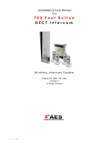
AES 703-HF-IBK3-US Spartan 703 Modular Wireless Audio Intercom System User manual

Category
Telephones
Type
User manual
TIP: Most technical calls received are due to installers using CAT5 or alarm cable to
power the unit.
NEITHER are rated to carry enough power! ( 1.2amp peak )
Please use the following cable:
Up to 2 metres ( 6 feet ) Use minimum 0.5mm2( 18 gauge )
Up to 4 metres ( 12 feet ) Use minimum 0.75mm2 ( 16 gauge )
Up to 8 metres ( 24 feet ) Use minimum 1.0mm2( 14 / 16 gauge )
POWER CABLE
TRANSMITTER
KEEP POWER SUPPLY AS CLOSE AS POSSIBLE.
SITE SURVEY RESTOCKING FEES MAY APPLY IF RETURNED AFTER INSTALL DUE TO SITE
ISSUES. PLEASE SEE FULL T&C’S ON OUR WEBSITE.
TIP: You must test to ensure that the system is capable of operating across
the desired range. Power the system on and place the handsets in their
expected locations around the property to ensure that the system is fully
functional and suitable for the site.
Tip: The transmitter should be mounted as high as
possible on the gate pillar or wall to maximise range.
Mounting close to the ground will reduce range and
is also more likely to be further restricted by long wet
grass, overhanging shrubs and vehicles.
Excessively long
cable!!
Power supply
Call point
Mains power Power supply
Call point
Mounting the Intercom
Mount the intercom at the desired height for pedestrian or car users. The camera angle is wide at
90 degrees to cover most scenarios.
Tip: Do not drill holes in the wall with the intercom in position,
otherwise dust may get around the camera window and impair the
camera view.
Mounting the Transmitter
INGRESS PROTECTION
We recommend sealing all entry holes for prevention of insects that can
cause issues with a risk of shorting out components.
To maintain the IP55 rating please follow the sealing instructions included.
(also available online)
LIGHTNING PRONE AREAS MUST USE SURGE PROTECTION
FOR POWER SUPPLY! See overleaf for more PCB details
Turn Over
Never drill holes in the top of
the enclosure. Cable entry
should be through the
bottom.
Screened CAT 5
4 meters max
603 Range
Intercom
Transmitter
(keep short for better audio)
Set up on a bench in workshop BEFORE going to site.
Program the unit in the comfort of your work bench and call
technical support should you have any questions.
Please read this entire manual before installing this
product. A full comprehensive manual is available on
our website for additional information.
* ALWAYS RANGE TEST THE UNIT ON SITE BEFORE INSTALLATION *
703 DECT -Modular Multi Button Wireless Audio Intercom System
STILL HAVING TROUBLE?
Find all of our support options such as Web Chat,
Full Manuals, Customer Helpline and more on
our website:
WWW.AESGLOBALUS.COM
NEED MORE ASSISTANCE?
+1 (321) 900 4599
SCAN THIS QR CODE TO BE BROUGHT TO OUR RESOURCES PAGE.
VIDEOS | HOW-TO GUIDES | MANUALS | QUICK START GUIDES
OPTIMAL RANGE
TIP: For longer range installations, locate the handset closest to the front of the
property and near a window if possible. Also ensure the antenna is mounted
pointing towards the handset.
Concrete walls can reduce the normal open-air range of up to 450 meters by
30-50% per wall.
SYSTEM INCOMPATIBLE WITH FOIL INSULATION.
Tip: For longer range installations, locate the handset close to the front of the property, near a
window if possible. Concrete walls can reduce the open-air range of 450 meters by 30-50% per wall.
Tip: To achieve best range, locate the handset away from other sources of radio transmission,
including other cordless phones, wifi routers, wifi repeaters, and laptops or PCs.
Handsets
703 Handsfree (Wall Mount) Receiver
Tip: The 603 HF unit has a built-in antenna/receiver, it is best to use this for short range installs.
For longer range installs, fit an external antenna.
Transmitter
Transmitter
Antenna
External
Antenna/Receiver
Intercom Intercom
Intercom
External antenna / receiver can be purchased separately from your local distributor.
Entrance
Pillar
Speech
Unit
150m
Typical
Side View
Entrance
Pillar
Speech
Unit
Side View
TRANSMITTER
0v
Optional
external
antenna
connections
Mounting screws
Code Button
Wall Fixing Mounting
screws
603 HF Mounting
External DECT
Antenna Portable
Audio Handset
Wall Mounted
Audio Panal
* ALWAYS RANGE TEST THE UNIT ON SITE BEFORE INSTALLATION *
703 DECT -Modular Multi Button Wireless Audio Intercom System
STILL HAVING TROUBLE?
Find all of our support options such as Web Chat,
Full Manuals, Customer Helpline and more on
our website:
WWW.AESGLOBALUS.COM
RELAY 1
+24V-
+-
101
220
RELAY 2
RELAY 1
1
2
3
4
C
12V
OUT
24V
AC DC
IN
RELAY
1
RELAY
2
+
-
N/C | C | N/O
N/O | C | N/C
GN D
24V
GN D
24V
GN D
24V
GN D
24V
GN D
24V
1 2 3 4 5 DC24V
(IN)
DC24V
(OUT)
DC24V
(OUT)
1
2
3
4
5
6
7
8
9
GND
1
2
3
4
5
6
7
8
9
GND
J1
J2
J3
J4
GND
1 2 3 4 5
N/O
C
N/C
Link both Relay 1’s to
allow either to release the
same door / gate.
WIRING DIAGRAM
Shield/Filter
Drain Cable
AES KP will come pre-
wired to the CallPoint
Insert Drain Cable into
0v (-) on Power IN
Code
Button
Optional
Antenna
Pairing
LEDs
Normally Open
Common
Normally Closed
RELAY CONNECTIONS
RELAY 1
RELAY 1
Transmitter Module
WARNING:
ESD SENSITIVE
To Gate Controller
24V AES Power Supply
SUFFICIENT POWER CABLE FOR
CALLPOINT REQUIRED ( 2x1mm2 )
LIGHTNING PRONE AREAS
MUST USE SURGE PROTECTION
FOR POWER SUPPLY!
COM
COM
BUTTON 1
KEEP SHORT
( 8m MAX! )
BUTTON 2
BUTTON 3
BUTTON 4
RELAY 1 R2
THE AES KEYPAD IS AN OPTIONAL EXTRA.
IF KEYPAD PRESENT, PLEASE SEE ‘KPX1200 GUIDE
FOR FULL INSTRUCTIONS ON PROGRAMMING AND
EXTENSIVE FEATURES.
Optional Programmable Keypad
RELAY 1 R2
12.000
24v IN EGRESS
RELAY 3
GROUND
+ - N.C. COM N.O. N.C. / N.O.
DATA
I/O
EG
IN
N.C. COM N.O. K or A
O/P
DU
OUT
DOOR
SENS
(-)
GND
O/P 1
INHIB.
INT
LOCK
TAMPER
N.C.
With our 703 DECT audio system you can
add up to a max of 4 portable handsets or
wall mounted versions.
(1 DEVICE WILL RING PER BUTTON)
Did you know? NEED MORE ASSISTANCE?
Please scan this QR Code to be
brought to our Resources page
where you can find all of our
guides and available resources.
MAGNETIC LOCK EXAMPLE
Follow this method when using a magnetic lock. If the relay in either the Transmitter or optional AES Keypad
is triggered it will temporarily lose power and allow the door/gate to release.
For installs without the optional AES Keypad; connect the POSITIVE of the Magnetic Lock PSU to N/C
terminal on Transmitter Relay.
N/O C N/C N/C C N/O
MAGNETIC LOCK
EXIT MAINS
POWER
MAX 24 VOLTS!
POWER ADAPTER
* M AGNETIC LOCK PSU SOLD SEPERATELY*
TRANSMITTER AES KEYPAD
TIP: Most technical calls received are due to installers using CAT5 or alarm cable
to power the unit.
NEITHER are rated to carry enough power! ( 1.2amp peak )
Please use the following cable:
Up to 2 metres ( 6 feet ) Use minimum 0.5mm2( 18 gauge )
Up to 4 metres ( 12 feet ) Use minimum 0.75mm2 ( 16 gauge )
Up to 8 metres ( 24 feet ) Use minimum 1.0mm2( 14 / 16 gauge )
POWER CABLE KEEP POWER SUPPLY AS CLOSE AS POSSIBLE.
* ALWAYS RANGE TEST THE UNIT ON SITE BEFORE INSTALLATION *
703 DECT -Modular Multi Button Wireless Audio Intercom System
STILL HAVING TROUBLE?
Find all of our support options such as Web Chat,
Full Manuals, Customer Helpline and more on
our website:
WWW.AESGLOBALUS.COM
DID YOU KNOW?
We also have GSM (Global system for
mobile) multi apartment intercom available.
2-4 buttons panels available. Each button
calls a different mobile. Easy to talk to
visitors and operate door/gates by phone.
The handset should ideally be charged for at least 8 hours before use. It is recommended to give it at least 60 minutes of charge
before performing the range test between the transmitter module and the handset inside.
N/C | C | N/O
N/O | C | N/C
Wall/Desk Mounted Audio Panel (603 / 703 / 705)
RE-CODING/ADDING EXTRA HANDSETS
INFORMATION ABOUT YOUR DECT HANDSET
Handsets will be
displayed in
order of H1, H2,
H3 & H4.
TI : ME
OK
ON/OFF VIBRATE
ON/OFF
RECEPTION
INDICATOR
BATTERY
LEVEL
VOICEMAIL
SYMBOL
PAIRING
LED
RELAY 2 RELAY 1
CODE BUTTON
STRIKE
LOCK
AC/DC STRIKE LOCK
WIRING EXAMPLE
Follow this method when using a Strike Lock with
the system. If used it will mean that if a relay in
either the Transmitter or optional AES Keypad is
triggered it will temporarily allow the door/gate
to release.
MAX 24 VOLTS!
POWER ADAPTER
MAINS
POWER
+
-
TRANSMITTER
AES KEYPAD
* STRIKE LOCK PSU SOLD SEPARATELY *
Do you require a custom wiring diagram for your site? Please send all
requests to [email protected] and we will do our best
to provide you with a supplement diagram suitable for your chosen
equipment.
We are constantly using your customer feedback to enhance all of
our guides / learning material for installers.
If you have any suggestions regarding this please send any
suggestions to [email protected]
Occasionally the system may need to be re-coded once installed.
If the handset does not ring when the call button is pressed,
the system may need to be re-coded.
( = FULL RE-CODE : STEP 1-5 )
(= ADDING A HANDSET : STEP 3-5 )
Step 1) Press and hold the CODE BUTTON inside the Transmitter Module for 5 seconds
until the audible tone is heard from the Intercom speaker.
Step 2) Then press the CODE BUTTON 14 times and wait until the melody is heard or the
LED turns off. Performing this step will remove ALL handsets currently synced (or partially
synced) to the system.
Step 3) Press and hold the CODE BUTTON inside the Transmitter Module for 5 seconds
until the blue pairing LED marked as D17 begins to flash.
Step 4) Then press and hold the CODE BUTTON on the handset until the red LED at the
top begins to flash. After a few seconds you will hear a melody play to let you know it has
successfully connected.
Step 5) Finally you should test the kit to ensure that everything is working as expected
by pressing the Call Button on the CallPoint to ensure the handset and/or wall mounted unit
receives the call and that the two way speech is functioning correctly.
( On 703 Transmitter the blue LED marked D17 should also flash. )
( Note: Doing this step will also clear ALL voicemails after reset. )
( An audible tone will be heard from the Intercom Speaker. )
( Repeat Steps 3 & 4 for each new handset. )
OK
TI : ME
Example shows the
location of the CODE
BUTTON that can be
found on the back of
the wall mounted unit.
CODE BUTTON
Can be found on
reverse side.
+24V-
+-
101
220
RELAY 2
RELAY 1
12.000
1
2
3
4
C
12V
OUT
24V
AC DC
IN
RELAY
1
RELAY
2
+
-
N/C | C | N/O
N/O | C | N/C
TRANSMITTER
CODE BUTTON
603/703 DECT
Adjusting the Relay trigger time
Press and hold the RELAY 2 button for 3 seconds, scroll through the menu
until you see ‘ti’.
Press the button to select the relay time. Press the key at any time to end
the process.
OK
Adjusting the time on your handset
Press and hold the button for 3 seconds, then use the up and keys to
select the hour and press button again to cycle to minutes. Once you have
finished adjusting the time then press the button to save. Press the key at
any time to end the process.
OK
OK
OK
Voicemail On/Off
You can turn the voicemail function of the system On/Off at any time. To start
press and hold the RELAY 2 button for 3 seconds then scroll through the menu
until you see Reand adjust this to ON or OFF then press to select.
OK
To listen to a voicemail, press . If there is more than 1 use and to select the message required and press to play.
Press RELAY 1 once to delete the message or press and hold it to delete all.
OK
OK
* ALWAYS RANGE TEST THE UNIT ON SITE BEFORE INSTALLATION *
703 DECT -Modular Multi Button Wireless Audio Intercom System
STILL HAVING TROUBLE?
Find all of our support options such as Web Chat,
Full Manuals, Customer Helpline and more on
our website:
WWW.AESGLOBALUS.COM
AES KPX1200 STANDARD OPERATIONS
N/O
C
N/C
Normally Open
Common
Normally Closed
RELAY CONNECTIONS
RELAY 1 R2
12 .000
24v IN EGRESS
RELAY 3
GROUND
+ - N.C. COM N.O. N.C. / N.O .
DATA
I/O
EG
IN
N.C. COM N.O.
K or A
O/P
DU
OUT
DOOR
SENS
(-)
GND
O/P 1
INHIB.
INT
LOCK
TAMPER
N.C.
AB
C
1 2 3 4 5 678 9
10
11
12
13
14
15
16
17
18
19
20
{1,2} 24v 2Amp = Regulated PSU
(Pre-wired for inside an AES Intercom System)
{9,15} Egress for PTE (Push To Exit)
If you wish to make use of this feature you must wire your PTE switch using
terminals 9& 15 marked as ‘ EG IN ’ and ‘ (-) GND.
Note: The egress feature on the keypad is designed to only activate Output 1. Ensure
that the entry you wish to gain access to via the PTE switch is connected to this output.
Programmable for Instant, Delay with Warning and/or Alarm Momentary or Holding
Contact for Exit Delay.
AES KPX1200 RELAY OUTPUT INFORMATION
{3,4,5} RELAY 1 = 5A/24VDC Max. N.C. & N.O. dry contacts.
1,000 (Codes) + 50 Duress Codes
{6,7,C} RELAY 2 = 1A/24VDC Max. N.C. & N.O. dry contacts.
100 (Codes) + 10 Duress Codes (COMMON port is determined by the Shunt Jumper marked
as C on the diagram. Connect your device to N.C. and N.O. and then move the jumper to
the required position and test.)
{10,11,12} RELAY 3 = 1A/24VDC Max. N.C. & N.O. dry contacts.
100 (Codes) + 10 Duress Codes
{19,20} Tamper Switch = 50mA/24VDC Max.
N.C. dry contact.
{A} BACK-LIT JUMPER = FULL/AUTO.
FULL The keypad gives dim backlit in standby. It turns to full backlit when a button is pressed,
then back to dim backlit 10 secs after the last button is pressed.
AUTO The backlit is OFF in standby. It turns to FULL backlit when a button is pressed, then
back to OFF 10 seconds after the last button is pressed.
{B} ALARM OUTPUT SETTING =( RESOURCES PAGE - ADVANCED WIRING OPTIONS )
LED 1 = RED/GREEN. It lights up in RED while one of the outputs is inhibited. It is flashing during inhibition paused. It is
also the Wiegand LED for feedback indication and will light up in GREEN.
LED 2 = AMBER. It flashes in Standby. It shows the system status in synchronization with the beeps.
LED 3 = RED/GREEN. It lights up in GREEN for OUTPUT 1 activation; and RED for OUTPUT 2 activation.
SUPPLEMENT WIRING DIAGRAMS CAN BE
FOUND ON OUR RESOURCE PAGE.
123
( LEDs ABOVE KEYPAD FRONT )
OUTPUT 2
N.C. |N.O.
^MOVE JUMPER LINK^
ALL THREE
OUTPUTS ARE
VOLT-FREE
CONTACTS.
Did you know?
Extra Prox cards and Prox Tags
can be purchased in packs of 10
& 50.
( PROX versions only )
NEED MORE ASSISTANCE?
Please scan this QR Code to be
brought to our Resources page
where you can find all of our
guides and available resources.
SITE SURVEY
TIP: If fitting this keypad as an independent system then no site survey is required.
If the keypad is included inside a callpoint then please follow the site survey details
included on the main product guide.
TIP: Most technical calls received are due to installers using CAT5 or alarm cable
to power the unit.
NEITHER are rated to carry enough power! ( 1.2amp peak )
Please use the following cable:
Up to 2 metres ( 6 feet ) Use minimum 0.5mm2( 18 gauge )
Up to 4 metres ( 12 feet ) Use minimum 0.75mm2 ( 16 gauge )
Up to 8 metres ( 24 feet ) Use minimum 1.0mm2( 14 / 16 gauge )
POWER CABLE
MAINS
POWER
NC
NO
COM
KEYPAD
RELAY
NC
NO
COM
SECONDARY
RELAY
MAGNETIC LOCK WIRING METHOD
NC
NO
COM
KEYPAD
RELAY
NC
NO
COM
SECONDARY
RELAY
STRIKE LOCK WIRING METHOD
MAX 24 VOLTS!
MAX 24 VOLTS!
MAGNETIC LOCK
STRIKE
LOCK
LOCK POWER SUPPLIES
ARE NOT INCLUDED AS
PART OF THE KIT.
* SOLD SEPARATELY *
* SOLD SEPARATELY *
MAINS
POWER
( LINKING WITH SECONDARY RELAY IS OPTIONAL FOR BOTH METHODS )
KEEP POWER SUPPLY AS CLOSE AS POSSIBLE.
* ALWAYS RANGE TEST THE UNIT ON SITE BEFORE INSTALLATION *
703 DECT -Modular Multi Button Wireless Audio Intercom System
STILL HAVING TROUBLE?
Find all of our support options such as Web Chat,
Full Manuals, Customer Helpline and more on
our website:
WWW.AESGLOBALUS.COM
7) Adding a new PROX card or tag:
1 0 1 0 0 1 #
10 = Relay 1
(1000 limit)
20 = Relay 2
(100 limit)
30 = Relay 3
(100 limit)
1= add MEMORY LOCATION
000 to 999 = Relay 1
001 to 100 = Relay 2
001 to 100 = Relay 3
SWIPE PROX
CARD or TAG
VALIDATE
* This example will add a PROX card/tag to location 001 on Relay 1*
PROX CARD
6) Change the programming code:
01? ? ? ? #
4-8 DIGIT CODE VALIDATE
* ALWAYS MAKE NOTE OF NEW CODE ONCE CHANGED *
LOCATION
Note: If you set a 4-8 digit code then
user codes must also be the same
amount of digits.
Example: If you set a 6 digit
programming code all access codes
must also be 6 digits long.
4) Change relay output times & modes:
5 1 0#
0= LATCHING MODE
1-99999 = MOMENTARY TRIGGER TIME (SECONDS)
VALIDATE
Note: Setting the relay time to 0will
change all codes for this output to
latching codes, re-enter same code
again to unlatch.
51 = Relay 1
52 = Relay 2
53 = Relay 3
OR 999 9 9
5) Adding a SUPER user code: (1 MAX)
02? ? ? ?#
‘SUPER’ CODE VALIDATE
LOCATION
Note: You can add one SUPER code as an
optional feature which allows a single code
to operate all 3 outputs. To use input
SUPER code followed by #then 1, 2or 3to
select.
Example - 5555#2
KEYPAD PROGRAMMING CONTINUED
KEYPAD PROGRAMMING
1) Enter programming mode:
0 0 00* *
DEFAULT PROGRAMMING CODE ENTER / EXIT PROGRAMMING
Note: Programming can only begin 60 seconds after powering the device on. * UNLESS OVERRIDDEN *
3) Delete ALL of the codes & cards saved in a relay group:
1 0 0 9 9 9 #
SUPER DELETE CODE VALIDATE
* This example will delete ALL of the codes stored for Relay 1*
10 = Relay 1
(1000 limit)
20 = Relay 2
(100 limit)
30 = Relay 3
(100 limit)
Note: Take care when deleting full
relay groups because once deleted
there is no way to restore these
previously stored codes to the
keypad.
The amber LED will remain SOLID once
you enter programming mode
successfully. Press ** again to leave
programming mode.
Note: In the event that the programming code has been forgotten or changed by accident, a DAP Reset of the keypad can be performed during the 60 second bootup phase. Pressing the PTE during this time or replicating this by shorting
terminals 9& 15 together with a jumper link the keypad will emit 2 short beeps if this step has been performed successfully. Then enter the DAP Code (Directly Access Programming Code) (8080**) on the front of the keypad as a
backdoor into programming mode which will allow you to now set a new programming code, as per Step 6 above.
PROGRAMMING CODE NOT WORKING?
* For example: 515# will set Relay 1
to trigger for 5seconds *
2) Adding and deleting a new keypad entry code:
1 0 2 0 0 0 ? ? ? ? #
10 = Relay 1
(1000 limit)
20 = Relay 2
(100 limit)
30 = Relay 3
(100 limit)
2= add
5= delete
MEMORY LOCATION
000 to 999 = Relay 1
001 to 100 = Relay 2
001 to 100 = Relay 3
4-8 DIGIT CODE VALIDATE
* This example will add code ????’ to location 000 on Relay 1*
Note: After using ‘5’ to delete a code just type
the memory location followed by #
8) Deleting a new PROX card or tag:
1 0 5 0 0 1 #
10 = Relay 1
(1000 limit)
20 = Relay 2
(100 limit)
30 = Relay 3
(100 limit)
5= delete MEMORY LOCATION
000 to 999 = Relay 1
001 to 100 = Relay 2
001 to 100 = Relay 3
VALIDATE
* This example will delete a PROX card/tag from location 001 on Relay 1*
Note: Keep in mind that keypad codes
and PROX card/tags must be saved in
their own separate memory locations.
If a keypad code is stored on location
035 this means a card cannot be added
to location 035.
(OPTIONAL PROGRAMMING FOR PROX MODELS ONLY)
* ALWAYS RANGE TEST THE UNIT ON SITE BEFORE INSTALLATION *
703 DECT -Modular Multi Button Wireless Audio Intercom System
STILL HAVING TROUBLE?
Find all of our support options such as Web Chat,
Full Manuals, Customer Helpline and more on
our website:
WWW.AESGLOBALUS.COM
Configuration for Latching via the handset
(keypad models only)
Relay 1 on the Keypad will have to be switched to a latching Relay see Keypad Programing Guide for Further instructions:
If you are still looking the keypad to trigger the gates you will have to use relay 2 or 3 and program accordingly.
Relay 1 on the transmitter will still trigger the gates but relay 2 will latch the gates from the transmitter
101101
220
101
220
RELAY 2RELAY 2
RELAY 1RELAY 1
1
2
3
4
C
12V
OUT
24V
AC DC
IN
RELAY
1
RELAY
2
+
-
RELAY 1 R2
12 .000
24v IN EGRESS
RELAY 3
GROUND
+ - N.C. COM N.O. N.C. / N.O .
DATA
I/O
EG
IN
N.C. COM N.O.
K or A
O/P
DU
OUT
DOOR
SENS
(-)
GND
O/P 1
INHIB.
INT
LOCK
TAMPER
N.C.
TI : METI : METI : ME
OK
Relay 2
(Latch)
Relay 1
(trigger)
* ALWAYS RANGE TEST THE UNIT ON SITE BEFORE INSTALLATION *
703 DECT -Modular Multi Button Wireless Audio Intercom System
STILL HAVING TROUBLE?
Find all of our support options such as Web Chat,
Full Manuals, Customer Helpline and more on
our website:
WWW.AESGLOBALUS.COM
Wall/Desk Mounted Audio Panel (603 / 703 / 705)
RE-CODING/ADDING EXTRA HANDSETS
Handsets will be
displayed in order
of H1, H2, H3 & H4.
(only 1 handset per
button)
Voicemail
When a call is not answered within 40 seconds,
the visitor can leave a message. Once complete,
the handset will display the symbol.
The unit can store up to 16 voice messages.
HANDSET BATTERIES INCLUDED
(2 x AAA 600mA Rechargeable)
Portable Audio Handset
Occasionally the system may need to be re-coded once installed.
If the handset does not ring when the call button is pressed,
the system may need to be re-coded.
( = FULL RE-CODE : STEP 1-5 )
(= ADDING A HANDSET : STEP 3-5 )
Step 1) Press and hold the CODE BUTTON inside the Transmitter Module for 5 seconds
until the audible tone is heard from the Intercom speaker.
Step 2) Then press the CODE BUTTON 14 times and wait until the melody is heard or the
LED turns off. Performing this step will remove ALL handsets currently synced (or partially
synced) to the system.
Step 3) Press and hold the CODE BUTTON inside the Transmitter Module for 5 seconds
until the audible tone is heard from the Intercom speaker.
Step 4) Then press and hold the CODE BUTTON on the handset until the red LED at the
top begins to flash, after a few seconds you will hear a melody play to let you know it has
successfully connected.
Step 5) Finally you should test the kit to ensure that everything is working as expected
by pressing the Call Button on the CallPoint to ensure the handset and/or wall mounted unit
receives the call and that the two way speech is functioning correctly.
( On 603 Transmitter the blue LED marked D17 should also flash. )
( Note: Doing this step will also clear ALL voicemails after reset. )
( On 603 Transmitter the blue LED marked D17 should also flash. )
( Repeat Steps 3 & 4 for each new handset. )
OK
TI : ME
Example shows the
location of the CODE
BUTTON that can be
found on the back of
the wall mounted unit.
CODE BUTTON
Can be found on
reverse side.
TRANSMITTER
CODE BUTTON
603/703 DECT 705 DECT
+24V-
+-
101
220
RELAY 2
RELAY 1
12.000
1
2
3
4
C
12V
OUT
24V
AC DC
IN
RELAY
1
RELAY
2
+
-
N/C | C | N/O
N/O | C | N/C
8.000
To listen to a voicemail, press . If there is more than 1 use and to select the message required
and press to play. Press once to Delete the message or press and hold to delete all.
OK
OK
Change Ring Tone
Press and the handset will ring with its
currently selected tone. Then you can press the
and keys to cycle through the available ring
tones. Then press to select and save the tone.
Change Ring Volume
Press and to increase or
decrease the ring volume and
then press to save.
OK
Call Another Handset
Press and the unit will display ‘HS1’, ‘HS2’, ‘HS3’, ‘HS4
depending on how many handsets are coded in the system.
Then use the and you can select the handset you wish
to call and then press to start the call.
OK
TI : ME
OK
ON/OFF VIBRATE
ON/OFF
RECEPTION
INDICATOR
BATTERY
LEVEL
VOICEMAIL
SYMBOL
PAIRING
LED
RELAY 2 RELAY 1
CODE BUTTON
OK
* ALWAYS RANGE TEST THE UNIT ON SITE BEFORE INSTALLATION *
703 DECT -Modular Multi Button Wireless Audio Intercom System
STILL HAVING TROUBLE?
Find all of our support options such as Web Chat,
Full Manuals, Customer Helpline and more on
our website:
WWW.AESGLOBALUS.COM
KEYPAD CODES
KEYPAD CODE LIST TEMPLATE
CLIENT NAME MEMORY
LOCATION KEYPAD CODE RELAY USED
(CIRCLE)
James 000 1234 1 2
3
Mary 001 4321 1 2
3
1 2
3
1 2
3
1 2
3
1 2
3
1 2
3
1 2
3
1 2
3
1 2
3
1 2
3
1 2
3
1 2
3
1 2
3
1 2
3
1 2
3
USE THIS AS A TEMPLATE OF HOW TO KEEP TRACK OF ALL OF THE KEYPAD CODES SAVED WITHIN
THE KEYPAD. FOLLOW THE FORMAT FROM THE EXAMPLES SET AND IF MORE TEMPLATES ARE
REQUIRED THEY CAN BE FOUND ON OUR WEBSITE OR FOLLOW THE QR CODE PROVIDED.
CLIENT NAME MEMORY
LOCATION PROX ID RELAY USED
(CIRCLE)
James 005 0001548796 1 2
3
Mary 006 0001589678 1 2
3
1 2
3
1 2
3
1 2
3
1 2
3
1 2
3
1 2
3
1 2
3
1 2
3
1 2
3
1 2
3
1 2
3
1 2
3
1 2
3
1 2
3
PROX IDs
PROX ID LIST TEMPLATE
STILL HAVING TROUBLE?
Find all of our support options such as
Web Chat, Full Manuals, Customer
Helpline and more on our website:
WWW.AESGLOBALUS.COM
AES KEYPAD
TROUBLESHOOTING
Q. The unit will not ring the handset.
A. Try re-coding the handset and transmitter as per instructions.
- Check push button wiring to the transmitter with multi-meter.
-Check power cable distance from power adaptor to transmitter is less than 4 meters.
Q. The person on the handset can hear interference on the call.
A. Check cable distance between the speech unit and transmitter. Shorten this if possible.
-Check cable used between the speech unit and transmitter is screened CAT5.
-Check that the screen of the CAT5 is connected to ground in the transmitter as per wiring instructions.
Q. Keypad code not operating the gate or door
A. Check if the corresponding relay indicator light comes on. If it does, then the fault is either a power problem
with excessive cable run, or wiring. If the relay can be heard clicking, then it is a wiring problem. If a click cannot
be heard, then it is likely a power problem. If the light does not activate and the keypad emits an error tone,
then the issue is likely a programming error.
Q. My handset will not recode
Try the process again. If it still does not work, delete the code from the transmitter. To delete code, press the
code button for 3 seconds and release. Then press it 7 times after which a tone should be heard. Then press
another 7 times. Now try re-coding the handset again as per the procedure.
Q. Range problem Handset works beside the intercom, but not from inside the building
A. Check that the power cable to the transmitter is within guidelines and is heavy enough gauge. Insufficient
power cabling will reduce transmission power! Check that there are not excessive objects blocking the signal,
like large dense shrubs, vehicles, foil lined wall insulation etc. Try to achieve line of sight between both devices.
Q. No speech in either direction
A. Check CAT5 wiring between speech panel and transmitter. Disconnect, re-strip cables and re-connect again.
Q. Handset will not charge
A. Try replacing both batteries with equivalent Ni-Mh batteries firstly. It is possible to have a dead cell in a
battery which can prevent both batteries from charging.
-Check for contamination or grease on the charging pins at the base of the handset (gently scratch with
screwdriver or wire wool).
This product is not a complete product until fully installed. It is therefore considered a component part of an overall system.
The installer is responsible to check that the end installation complies with local regulatory requirements. This equipment
forms part of a “fixed installation”.
Note: The manufacturer cannot legally offer technical support to non-qualified gate or door installers. End users should
employ the services of a professional install company to commission or support this product!
INTERCOM MAINTENANCE
Bug ingress is a common issue in unit failures. Ensure that all components are sealed accordingly and
check occasionally. (Do not open the panel in the rain / snow unless correctly equipped to keep the
internals dry. Ensure the unit is securely closed after maintenance)
Ensure that the transmitter box (603/703) or antenna (705) do not get blocked by trees, shrubs or other
obstacles overtime as this may disrupt the signal to the handsets.
If you have an AB, AS, ABK, ASK callpoint it will have silver edges which are marine grade stainless steel
so in normal weather conditions should not rust however it can dull or dis-colour over time. This can be
polished with a suitable stainless-steel cleaner and cloth.
ENVIRONMENTAL INFORMATION
The equipment that you bought has required the extraction and use of natural resources for its
production. It may contain hazardous substances for the health and the environment. In order to avoid
the dissemination of those substances in our environment and to diminish the pressure on the natural
resources, we encourage you to use the appropriate take-back systems. Those systems will reuse or
recycle most of the materials of your end life equipment.
The crossed-bin symbol marked in your device invites you to use
those systems.
If you need more information on the collection, reuse and recycling systems, please contact your local
or regional waste administration. You can also contact AES Global Ltd for more information on the
environmental performances of our products.
FCC ID: 2ALPX-603TX and 2ALPX-603EH
Grantee: Advanced Electronic Solutions Global Ltd
This device complies with Part 15D of FCC rules.
Operation is subject to the following two conditions:
(1) this device may not cause harmful interference, and (2) this device must accept any interference received,
including interference that may cause undesired operation. Output power listed is conducted.
This device must be installed to provide a separation distance of at least 20 cm from all persons and must not be co-
located or operating in conjunction with any other antenna or transmitter.
End-users and installers must be provided with antenna installation instructions and transmitter operating
conditions for satisfying RF exposure compliance. This device has 20MHz and 40 MHz bandwidth modes.
FCC Approval
STILL HAVING TROUBLE?
Find all of our support options such as Web Chat, Full Manuals, Customer
Helpline and more on our website:
WWW.AESGLOBALUS.COM
+1 (321) 900 4599
* ALWAYS RANGE TEST THE UNIT ON SITE BEFORE INSTALLATION *
703 DECT -Modular Multi Button Wireless Audio Intercom System
STILL HAVING TROUBLE?
Find all of our support options such as Web Chat,
Full Manuals, Customer Helpline and more on
our website:
WWW.AESGLOBALUS.COM
  • Page 1 1
  • Page 2 2
  • Page 3 3
  • Page 4 4
  • Page 5 5
  • Page 6 6
  • Page 7 7
  • Page 8 8
  • Page 9 9
  • Page 10 10

AES 703-HF-IBK3-US Spartan 703 Modular Wireless Audio Intercom System User manual

Category
Telephones
Type
User manual

Ask a question and I''ll find the answer in the document

Finding information in a document is now easier with AI