Agilent Technologies Video Gaming Accessories E3632A User manual

Type
User manual

This manual is also suitable for

Service Guide
3DUW1XPEHU(
$SULO
)RU:DUUDQW\LQIRUPDWLRQUHIHUWRWKHEDFNRIWKHPDQXDO
&RS\ULJKW$JLOHQW7HFKQRORJLHV,QF
$OO5LJKWV5HVHUYHG
$JLOHQW($
'&3RZHU6XSSO\
The Agilent E3632A is a high performance 120 watt-dual range DC power
supply with GPIB and RS-232 interfaces. The combination of bench-top and
system features in this power supply provides versatile solutions for your
design and test requirements.
Convenient bench-top features
Dual range
Easy-to-use knob control settings
Highly visible vacuum-fluorescent display meters
Hghl accuracy and high resolution
Remote voltage sensing
Overvoltage and overcurrent protection
Output on/off
Excellent load and line regulation and low ripple and noise
Operating states storage
Portable, ruggedized case with non-skid feet
Flexible system features
GPIB (IEEE-488) and RS-232 interfaces are standard
SCPI (Standard Commands for Programmable Instruments) compatibility
I/O setup easily done from front-panel
Software calibration, no internal adjustments required
Agilent E3632A
DC Power Supply
2
The Front Panel at a Glance
1 15V/7A range selection key
2 30V/4A range selection key
3 Overvoltage protection key
4 Overcurrent protection key
5 Display limit key
6 Recall operating state key
7 Store operating state/Local key
8 Error/Calibrate key
9 I/O Configuration/Secure key
10 Output On/Off key
11 Control knob
12 Resolution selection keys
13 Voltage/current adjust selection key
3
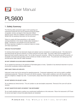
1 15V/7A range selection key Selects the 15V/7A range and allows the full rated output
to 15V7A.
2 30V/4A range selection key Selects the 30V/4A range and allows the full rated output
to 30V/4A.
3 Overvoltage protection key Enables or disables the overvoltage protection function,
sets trip voltage level, and clears the overvoltage condition.
4 Overcurrent protection key Enables or disables the overcurrent protection function,
sets trip current level, and clears the overcurrent condition.
5 Display limit key Shows voltage and current limit values on the display and allows
knob adjustment for setting limit values.
6 Recall operating state key Recalls a previously stored operating state from location
"1", "2", or "3".
7 Store operating state / Local key
1
Stores an operating state in location "1", "2", or
"3" / or returns the power supply to local mode from remote interface mode.
8 Error / Calibrate key
2
Displays error codes generated during operations, self-test
and calibration / or enables calibration mode (the power supply must be unsecured
before performing calibration).
9 I/O Configuration / Secure key
3
Configures the power supply for remote interfaces
/ or secure or unsecure the power supply for calibration.
10 Output On/Off key Enables or disables the power supply outputs. This key toggles
between on and off.
11 Control knob Increases or decreases the value of the blinking digit by turning
clockwise or counter clockwise.
12 Resolution selection keys Move the blinking digit to the right or left.
13 Voltage/current adjust selection key Selects the knob control function for voltage
or current adjustment.
1
The key can be used as the "Local" key when the power supply is in the remote
interface mode.
2
You can enable the "calibration mode" by holding down this key when you turn on
the power supply.
3
You can use it as the "Secure" or "Unsecure" key when the power supply is in the
calibration mode.
4
Front-Panel Voltage and Current Limit Settings
You can set the voltage and current limit values from the front panel using the
following method.
1 Select the desired range using the range selection keys after turning on the power
supply.
2 Press the key to show the limit values on the display.
3 Move the
blinking digit to the appropriate position using the resolution selection keys
and change the blinking digit value to the desired vltage limit by turning the control
knob. If the display limit times out, press the key again.
4 Set the knob to current control mode using the voltage/current adjust selection key.
5 Move the blinking digit to the appropriate position using the resolution selection keys
and change the blinking digit value to the desired current limit by turning the control
knob.
6 Press the key to enable the output. After about 5 seconds, the
display will go to the output monitor mode automatically to display the voltage and
current at the output or the display will go to the monitor mode immediately by pressing
the
key again.
Note
All front panel keys and controls can be disabled with remote interface
commands. The Agilent E3632A must be in "Local" mode for the front panel
keys and controls to function.
Use the voltage/current adjust selection key, the resolution selection keys, and
the control knob to change the voltage and current limit value.
Display Limit
Display Limit
Output On/Off
Output On/Off
5
Display Annunciators
Adrs Power supply is addressed to listen or talk over a remote interface.
Rmt Power supply is in remote interface mode.
15V Shows the 15V/7A range is selected.
30V Shows the 30V/4A range is selected.
OVP The overvoltage protection function is enabled when the annunciator
turns on or the overvoltage protection circuit has caused the power
supply to shutdown when the annunciator blinks.
OCP The overcurrent protection function is enabled when the annunciator
turns on or the overcurrent protection circuit has caused the power
supply to shutdown when the annunciator blinks.
CAL The power supply is in calibration mode.
Limit The display shows the limit values of voltage and current.
ERROR Hardware or remote interface command errors are detected and the error
bit has not been cleared.
OFF The output of the power supply is disabled (See
page 52 for more
information
).
Unreg The output of the power supply is unregulated (output is neither CV
nor CC).
CV The power supply is in constant voltage mode.
CC The power supply is in constant current mode.
To review the display annunciators, hold down key as you
turn on the power supply.
Display Limit
6
The Rear Panel at a Glance
Use the front-panel key to:
Select the GPIB or RS-232 interface (see chapter 3).
Set the GPIB bus address (see chapter 3).
Set the RS-232 baud rate and parity (see chapter 3).
1 Power-line voltage setting
2 Power-line fuse-holder assembly
3 AC inlet
4 Power-line module
5 GPIB (IEEE-488) interface connector
6 RS-232 interface connector
I/O Config
7
In This Book
Specifications Chapter 1 lists the power supply’s specifications and
describes how to interpret these specifications.
Quick Start
Chapter 2 prepares the power supply for use and helps you get
familiar with the front-panel features.
Calibration Procedures Chapter 3 provides performance verification and
calibration procedures.
Theory of Operation Chapter 4 describes block and circuit level theory
related to the operation of the power supply.
Service Chapter 5 provides guidelines for returning your power supply to
Agilent Technologies for servicing, or for servicing it yourself.
Replaceable Parts Chapter 6 contains a detailed parts list of the power
supply.
Backdating Chapter 7 describes the difference between this manual and
older issues of this manual.
Schematics Chapter 8 contains the power supply's schematics, disassembly
drawings, and component locator drawings.
If you have questions relating to the operation of the power supply, call
1-800-452-4844 in the United States, or contact your nearest Agilent
Technologies Sales Office.
If your Agilent E3632A fails within three years of purchase, Agilent will
repair or replace it free of charge. Call 1-800-258-5165 ("Express
Exchange") in the United States, or contact your nearest Agilent
Technologies Sales Office.
8
9
Contents
Contents
Chapter 1 Specifications
Performance Specifications 15
Supplemental Characteristics 17
Chapter 2 Quick Start
To Prepare the Power Supply for Use 23
To Check the Rated Voltages of the Power Supply 25
To Check the Rated Currents of the Power Supply 26
To Use the Power Supply in Constant Voltage Mode 28
To Use the Power Supply in Constant Current Mode 30
To Store and Recall the Instrument State 32
To Program Overvoltage Protection 34
Setting the OVP Level and Enable the OVP Circuit 34
Checking OVP Operation 35
Clearing the Overvoltage Condition 35
To Program Overcurrent Protection 37
Setting the OCP Level and Enable the OCP Circuit 37
Checking OCP Operation 38
Clearing the Overcurrent Condition 38
To Rack Mount the Power Supply 39
Chapter 3 Calibration Procedures
Agilent Technologies Calibration Services 43
Calibration Interval 43
Automating Calibration Procedures 44
Recommended Test Equipment 44
Test Considerations 45
Performance Verification Tests 46
Self-Test 46
Performance Verification Tests 46
Measurement Techniques 47
Setup for Most Tests 47
Electronic Load 48
Current-Monitoring Resistor 48
Programming 48
10
Contents
Contents
Chapter 3 Calibration Procedures (continued)
Constant Voltage (CV) Verifications 49
Constant Voltage Test Setup 49
Voltage Programming and Readback Accuracy 49
CV Load Regulation 50
CV Line Regulation 50
Normal Mode Voltage Noise (CV Ripple and Noise) 51
Load Transient Response Time 52
Constant Current (CC) Verifications 53
Constant Current Test Setup 53
Current Programming and Readback Accuracy 53
CC Load Regulation 54
CC Line Regulation 55
Normal Mode Current Noise (CC Ripple and Noise) 55
Common Mode Current Noise 56
Performance Test Record for Agilent Technologies E3632A 57
CV Performance Test Record 57
CC Performance Test Record 57
Calibration Security Code 58
To Unsecure the Power Supply for Calibration 59
To Unsecure the Power Supply Without the Security Code 60
Calibration Count 61
Calibration Message 61
General Calibration/Adjustment Procedure 62
Voltage and OVP Calibration 63
Current and OCP Calibration 65
Aborting a Calibration in Progress 68
Calibration Record for Agilent Technologies E3632A 69
Error Messages 70
Calibration Program 72
Chapter 4 Theory of Operation
Block Diagram Overview 79
AC Input and Bias Supplies 81
Floating Logic 82
D-to-A Converter 84
A-to-D Converter 85
Power Mesh and Control 86
Earth-Referenced Logic 88
Front Panel 88
11
Contents
Contents
Chapter 5 Service
Operating Checklist 91
Types of Service Available 92
Repacking for Shipment 93
Electrostatic Discharge (ESD) Precautions 94
Surface Mount Repair 94
To Replace the Power-Line Fuse 94
To Disconnect the Output Using an External Relay 95
Troubleshooting Hints 96
Self-Test Procedures 98
Chapter 6 Replaceable Parts
Replaceable Parts 102
To Order Replaceable Parts 102
Backdating and Part Changes 102
E3632-60002 Main PC Assembly 103
E3632-60004 Front-Panel Display PC Assembly 111
E3632-60005 Front Frame Assembly 112
E3632A Power Supply Assembly 112
Manufacturer’s List 113
Chapter 7 Backdating
Chapter 8
Mechanical Disassembly 103
Component Locator 120
Power Circuit and Protection Circuit Schematic 121
Bias Supply Schematic 122
ADC and DAC System Schematic 123
Floating Logic Schematic 124
Earth-Referenced Logic Schematic 125
Display and Keyboard Schematic 126
12
Contents
Contents
1
1
Specifications
14
Specifications
The
performance
specifications are listed in the following pages. Specifications
are warranted in the temperature range of 0 to 40°C with a resistive load.
Supplemental
characteristics, which are not warranted but are descriptions of
performance determined either by design or testing. Chapter 3 "Calibration
Procedures" contains procedures for verifying the performance specifications.
Chapter 1 Specifications
Performance Specifications
15
1
Performance Specifications
Output Ratings (@ 0°C - 40°C)
Low range 0 to +15 V/0 to 7 A
High range 0 to +30 V/0 to 4 A
Programming Accuracy
[1]
12 months (@ 25°C ± 5°C), ±(% of output + offset)
Voltage 0.05% + 10 mV
Current 0.2% + 10 mA
Readback Accuracy
[1]
12 months (over GPIB and RS-232 or front panel with respect
to actual output @ 25°C ± 5°C), ±(% of output + offset)
Voltage 0.05% + 5 mV
Current 0.15 % + 5 mA
Ripple and Noise (with outputs ungrounded, or with either output terminal grounded,
20 Hz to 20 MHz)
Normal mode voltage <0.35 mV rms and 2 mV p-p
Current <2 mA rms
Common mode current <1.5 mA rms
Load Regulation, ±(% of output + offset)
Change in output voltage or current for any load change within ratings with remote
sensing connected.
Voltage <0.01% + 2 mV
Current <0.01% + 250 mA
Line Regulation, ±(% of output + offset)
Change in output voltage and current for any line change within ratings
Voltage <0.01% + 2 mV
Current <0.01% + 250 mA
[1]
Accuracy specifications are after an 1-hour warm-up with no load and calibration at
25°C
Chapter 1 Specifications
Performance Specifications
16
Programming Resolution
Voltage 1 mV
Current 0.5 mA
Readback Resolution
Voltage 0.5 mV
Current 0.1 mA
Front Panel Resolution
Voltage 1 mV
Current 1 mA
Transient Response Time
Less than 50 msec for output recover to within 15 mV following a change in output
current from full load to half load or vice versa
Command Processing Time
Average time for output voltage to begin to change after receipt of digital data when
the power supply is connected directly to the GPIB or RS-232 is less than 100 msec.
OVP and OCP Accuracy, (% of output + offset)
OVP 0.5% + 0.5 V
OCP 0.5% + 0.5 A
Activation time
: Average time for output to start to drop after OVP or OCP condition
occurs.
OVP <1.5 msec when the trip voltage is equal or greater than 3 V
<10 msec when the trip voltage is less than 3 V
OCP <10 msec
Chapter 1 Specifications
Supplemental Characteristics
17
1
Supplemental Characteristics
Output Programming Range (maximum programmable values)
Low range 0 to 15.45 V/0 to 7.21 A
High range 0 to 30.9 V/0 to 4.12 A
OVP 1 V to 32 V
OCP 0 A 7.5 A
Remote Sensing Capability
Voltage drop Up to 1 V per each lead
Load regulation Add 5 mV to spec for each 1-volt change in the + output lead
due to load current changes.
Load voltage Subtract voltage drop in load leads from specified output
voltage atiing.
Temperature Coefficient, ±(% of output + offset)
Maximum change in output/readback per °C after a 30-minute warm-up
Voltage 0.01% + 3 mV
Current 0.02% + 3 mA
Stability, ±(% of output + offset)
Following a 1 hour warm-up, change in output over 8 hours under constant load, line,
and ambient temperature
Voltage 0.02% + 1 mV
Current 0.1% + 1 mA
Voltage Programming Speed
Maximum time required for output voltage to settle within 1% of its total excursion (for
resistive load). Excludes command processing time.
Full load
No load
Up 50 msec 20 msec
Down 45 msec 400 msec
Chapter 1 Specifications
Supplemental Characteristics
18
Output Terminal Isolation (maximum, from chassis ground)
±60 Vdc when connecting shorting conductors without insulation to the (+) output to
the (+) sense and the (-) output and the (-) sense terminals.
±240 Vdc when connecting insulated shorting conductors to the (+) output to the (+)
sense and the (-) output and the (-) sene terminals.
AC Input Ratings (selectable via rear panel selector)
std 115 Vac ± 10%, 47 to 63 Hz
opt 0E3 230 Vac ± 10%, 47 to 63 Hz
opt 0E9 100 Vac ± 10%, 47 to 63 Hz
Maximum Input Power
500 VA with full load
Cooling
Fan cooled
Operating Temperature
0 to 40°C for full rated output. At higher temperatures, the output current is derated
linearly to 50% at 55°C maximum temperature.
Output Voltage Overshoot
During turn-on or turn-off of ac power, output plus overshoot will not exceed 1 V if the
output control is set to less than 1 V. If the output control is set to 1 V or higher, there
is no overshoot.
Programming Language
SCPI (Standard Commands for Programmable Instruments)
State Storage Memory
Three (3) user-configurable stored states
Recommended Calibration Interval
1 year
Chapter 1 Specifications
Supplemental Characteristics
19
1
Dimensions
*
213 mmW x 133 mmH x 348 mmD (8.4 x 5.2 x 13.7 in)
*See below for detailed information.
Weight
Net 9.5 kg (21 lb)
Shipping 12 kg (26 lb)
Figure 1-1. Dimensions of Agilent E3632A Power Supply
  • Page 1 1
  • Page 2 2
  • Page 3 3
  • Page 4 4
  • Page 5 5
  • Page 6 6
  • Page 7 7
  • Page 8 8
  • Page 9 9
  • Page 10 10
  • Page 11 11
  • Page 12 12
  • Page 13 13
  • Page 14 14
  • Page 15 15
  • Page 16 16
  • Page 17 17
  • Page 18 18
  • Page 19 19
  • Page 20 20
  • Page 21 21
  • Page 22 22
  • Page 23 23
  • Page 24 24
  • Page 25 25
  • Page 26 26
  • Page 27 27
  • Page 28 28
  • Page 29 29
  • Page 30 30
  • Page 31 31
  • Page 32 32
  • Page 33 33
  • Page 34 34
  • Page 35 35
  • Page 36 36
  • Page 37 37
  • Page 38 38
  • Page 39 39
  • Page 40 40
  • Page 41 41
  • Page 42 42
  • Page 43 43
  • Page 44 44
  • Page 45 45
  • Page 46 46
  • Page 47 47
  • Page 48 48
  • Page 49 49
  • Page 50 50
  • Page 51 51
  • Page 52 52
  • Page 53 53
  • Page 54 54
  • Page 55 55
  • Page 56 56
  • Page 57 57
  • Page 58 58
  • Page 59 59
  • Page 60 60
  • Page 61 61
  • Page 62 62
  • Page 63 63
  • Page 64 64
  • Page 65 65
  • Page 66 66
  • Page 67 67
  • Page 68 68
  • Page 69 69
  • Page 70 70
  • Page 71 71
  • Page 72 72
  • Page 73 73
  • Page 74 74
  • Page 75 75
  • Page 76 76
  • Page 77 77
  • Page 78 78
  • Page 79 79
  • Page 80 80
  • Page 81 81
  • Page 82 82
  • Page 83 83
  • Page 84 84
  • Page 85 85
  • Page 86 86
  • Page 87 87
  • Page 88 88
  • Page 89 89
  • Page 90 90
  • Page 91 91
  • Page 92 92
  • Page 93 93
  • Page 94 94
  • Page 95 95
  • Page 96 96
  • Page 97 97
  • Page 98 98
  • Page 99 99
  • Page 100 100
  • Page 101 101
  • Page 102 102
  • Page 103 103
  • Page 104 104
  • Page 105 105
  • Page 106 106
  • Page 107 107
  • Page 108 108
  • Page 109 109
  • Page 110 110
  • Page 111 111
  • Page 112 112
  • Page 113 113
  • Page 114 114
  • Page 115 115
  • Page 116 116
  • Page 117 117
  • Page 118 118
  • Page 119 119
  • Page 120 120
  • Page 121 121
  • Page 122 122
  • Page 123 123
  • Page 124 124
  • Page 125 125
  • Page 126 126
  • Page 127 127
  • Page 128 128

Agilent Technologies Video Gaming Accessories E3632A User manual

Type
User manual
This manual is also suitable for

Ask a question and I''ll find the answer in the document

Finding information in a document is now easier with AI