Quick Reference - 1
19
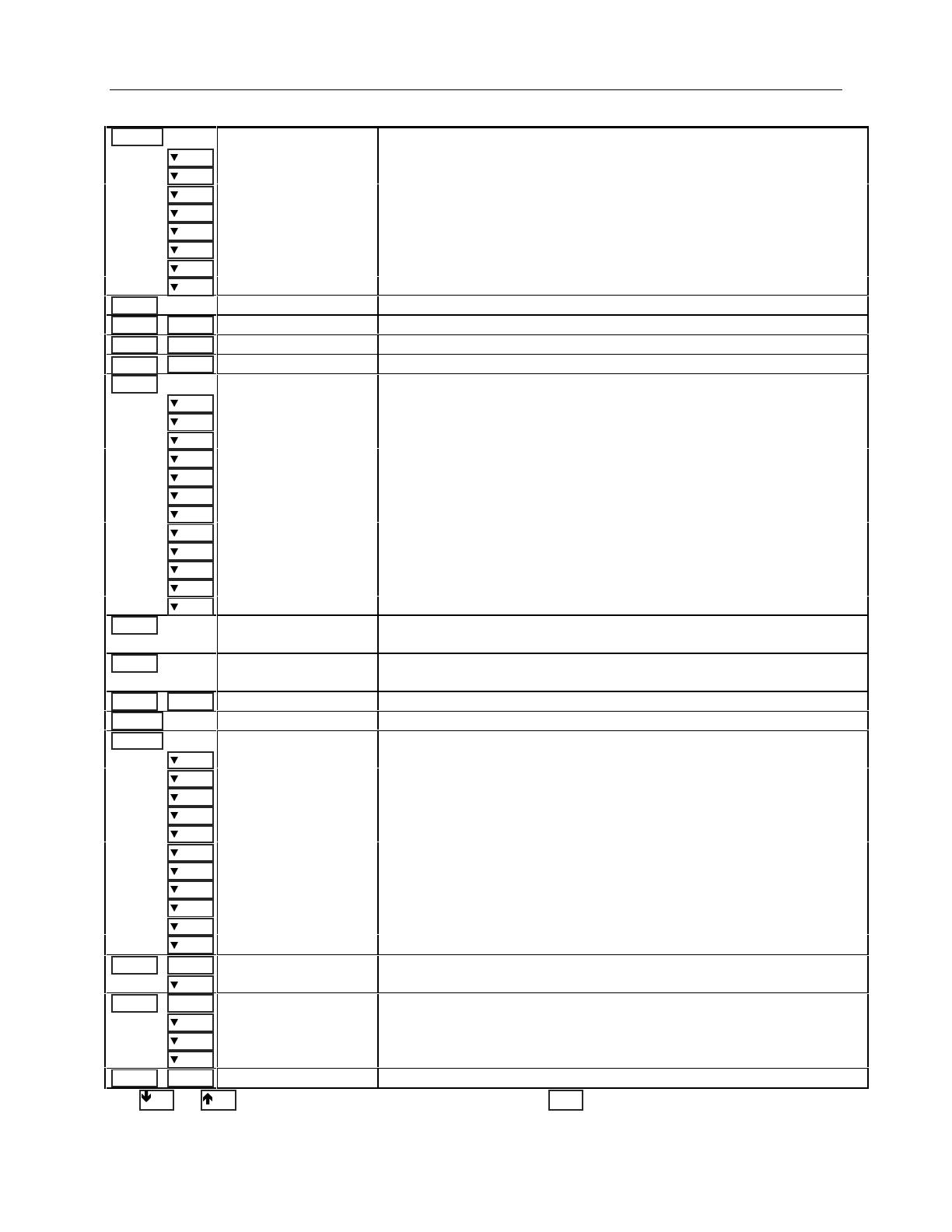
Front Panel Menus - At a Glance
ADDRESS 7 Sets the GPIB Address
INTF GPIB Selects an interface (GPIB | RS232)
1
BAUDRATE 300 Selects baud rate (300 | 600 | 1200 | 2400 | 4800 | 9600)
1
PARITY NONE Selects message parity (NONE | EVEN | ODD | MARK | SPACE)
1
FLOW NONE Selects flow control (XON-XOFF | RTS-CTS | DTR-DSR | NONE)
1
LANG SCPI Selects language (SCPI | COMP)
1
REMOTE FP OFF Enables or disables Agilent 14575A remote front panel (ON | OFF)
ROM: A.00.00 Displays the firmware revision of the instrument
SN: US12345678 Displays the serial number of the instrument
*RCL 0 Recalls the instrument state
*SAV 0 Saves the present instrument state
ERROR 0 Displays the number of errors in the SCPI error queue
2
5.000V 0.104A Toggles the display between output 1 and output 2 (output 2 shown)
1
12.000V
1
0.204A Measures the output voltage and current (output 1 shown)
1
12.500V MAX Measures the peak output voltage
2
1
1.000V MIN Measures the minimum output voltage
2
1
12.330V HIGH Measures the high level of a voltage pulse waveform
2
1
0.080V LOW Measures the low level of a voltage pulse waveform
2
1
12.000V RMS Measures the rms voltage
2
1
0.350A MAX Measures the peak output current
2
1
0.050A MIN Measures the minimum output current
2
1
0.400A HIGH Measures the high level of a current pulse waveform
2
1
0.012A LOW Measures the low level of a current pulse waveform
2
1
0.210A RMS Measures the rms current
2
1
12.000V DC:DVM Measures the dc voltage on the DVM input
3
1
12.000V RMS:DVM Measures the rms voltage on the DVM input
3
1
VOLT 12.000
2
VOLT 2.000
Sets the voltage of output 1 on all models
Sets the voltage of output 2
4
1
CURR 2.000
2
CURR 1.000
Sets the current limit of output 1 on all models
Sets the current limit of output 2
4
Not available
OVERCURRENT Protection status (example shows overcurrent tripped)
*RST Places the dc source in the factory-default state
COUPLING ALL Couples or decouples output 1 and output 2 (NONE or ALL)
3
TYPE:CAP LOW Sets the output capacitance compensation (HIGH, H2, or LOW)
PON:STATE RST Select the power-on state command (RST or RCL0)
PROT:DLY 0.08 Sets the output protection delay in seconds
RI LATCHING Sets the remote inhibit mode (LATCHING, LIVE, or OFF)
DFI OFF Sets the discrete fault indicator state (ON or OFF)
DFI:SOUR OFF Selects the DFI source (QUES, OPER, ESB, RQS, or OFF)
PORT RIDFI Sets the output port functions (RIDFI or DIGIO)
DIGIO 7 Sets and reads the I/O port value (0 through 7)
SENSE:PROT OFF Enables or disables the open sense lead detect circuit (ON or OFF)
1
REL:MODE DD Sets the relay mode for Option 521 units (DD, HD, DH, or HH) (output 1 shown)
VOLT:PROT 22 Sets the overvoltage protection level
PROT:STAT ON Enables or disables overvoltage protection (ON or OFF)
CURR:RANG HIGH Sets the current range (HIGH, LOW, or AUTO)
2
CURR:DET ACDC Sets the current measurement detector (ACDC or DC)
2
TINT 46.8 Sets the time interval for a front panel measurement in seconds
POINT 2048 Sets the buffer size for a front panel measurement
CAL ON Accesses calibration menu (See Appendix B).
Use and to select parameters (table shows factory defaults). Use to exit any menu.
1
Not valid for Agilent Model 66309B
2
Not valid for Agilent Model 66111A
3
Only valid for Agilent Model 66309B/D
4
Only valid for Agilent Model 66311D/66309D
Meter


