Page is loading ...

Distributed by
Any reference to Raytheon or
RTN in this manual should be
interpreted as Raymarine.
The names Raytheon and RTN
are owned by the
Raytheon Company.

L750 Fishfinder
Operation Handbook
Raymarine


Contents
i
Contents
Chapter 1: Introduction.................................................................. 1
About the L750 Fishfinder ........................................................ 1
System Components ............................................................... 1
Standard Equipment .......................................................... 1
Standard Transducers ....................................................... 2
Optional Accessories ......................................................... 2
Chapter 2: Installation.................................................................... 4
About the Transducer .............................................................. 4
Selecting the Correct Type of Transducer.................................. 5
Installing a Thru-Hull Transducer .............................................. 6
Before You Begin the Installation......................................... 7
Selecting the Best Location for the Transducer..................... 7
Mounting the Fairing Block ................................................. 8
Installing a Thru-Hull Transducer....................................... 10
Assembling the Transducer Bracket.................................. 11
Positioning the Transom-Mount Transducer ...................... 12
Mounting the Transom-Mount Transducer......................... 13
Mounting the Optional Sidelooker Transducer ................... 15
Installation Notes – In-Hull Transducer .............................. 16
Installation Notes – Trolling Motor Transducer.................... 17
Installation Notes – Transducer for Speed and
Temperature Only............................................................ 17
EMC Installation Guidelines ................................................... 17
Mounting the Display Unit....................................................... 19
Standard Mount ............................................................... 19
Flush Mount .................................................................... 19
Installing the Transducer Cable .............................................. 21
Thru-Hull and Transom-Mount Installation ......................... 21

L750 Fishfinder: Installation and Operation Handbook
ii
Sidelooker Option ............................................................ 22
Installation with Separate Speed and
Temperature Sensors ...................................................... 23
Making the DC Power Connections ........................................ 23
Calibrating the Sensors .......................................................... 25
Chapter 3: Operating Instructions ............................................... 27
Controls on Display Unit ......................................................... 27
Turning the Power On and Off ................................................ 30
Turning the Power On – Initial Use .................................... 30
Turning the Power On – Routine Operation........................ 31
Turning the Power Off ...................................................... 31
Setup Memory and Master Reset ........................................... 32
Operating Pages ................................................................... 32
Downlook Page ............................................................... 33
Fish Indications................................................................ 37
Bottom Indications ........................................................... 38
Window Page .................................................................. 39
Digital Page ..................................................................... 41
Modifying Displays ................................................................ 42
Frequency Soft Key ......................................................... 42
Zoom Soft Key ................................................................. 44
Bottom Lock Soft Key ....................................................... 47
A-Scope (Bottom Coverage) Key ...................................... 49
Other Control Buttons ............................................................ 50
Display............................................................................ 50
Gain/ Sensitivity ............................................................... 50
Range............................................................................. 52
VRM ............................................................................... 53
Multi-purpose .................................................................. 54

Contents
iii
Alarms ............................................................................ 55
Mark ............................................................................... 57
About the Sidelooker Feature ................................................. 58
The Sidelooker Page........................................................ 59
The Split-Screen Sidelooker Page .................................... 61
Turning On the Sidelooker Feature ................................... 61
Setting the Sidelooker Range ........................................... 61
Setting the Sidelooker Gain/Sensitivity .............................. 62
Chapter 4: Setup Instructions ...................................................... 63
The Setup Menus .................................................................. 63
Chart Speed Setting ......................................................... 63
Log Reset........................................................................ 64
System Setup Menu ........................................................ 64
Resetting the Unit to Factory Defaults ..................................... 68
Default Settings ..................................................................... 68
Chapter 5: Maintenance and Troubleshooting ............................ 69
Cleaning Instructions ............................................................. 69
Troubleshooting Suggestions ................................................. 69
Servicing a Thru-Hull Transducer ........................................... 73
How to Contact Raymarine .................................................... 73
Parts Listing .......................................................................... 75
Chapter 6: Specifications ............................................................ 78
General Information............................................................... 78
Fishfinder Functions .............................................................. 78
Connector Diagram ............................................................... 79
Dimensions........................................................................... 80
Glossary of Terms ....................................................................... 81

L750 Fishfinder: Installation and Operation Handbook
iv
Figures
Fig. 2-1 Transducer Types................................................... 4
Fig. 2-2 Thru-Hull Transducer .............................................. 6
Fig. 2-3 Best Transducer Locations ...................................... 8
Fig. 2-4 Installing a Fairing Block .......................................... 9
Fig. 2-5 Mounting the Transducer Correctly ........................ 11
Fig. 2-6 Assembling the Transducer Bracket....................... 11
Fig. 2-7 Transducer Mounted on Transom .......................... 12
Fig. 2-8 Transducer Bracket, Side View .............................. 13
Fig. 2-9 Correct Mounting Position ..................................... 14
Fig. 2-10 Mounting the Transducer ...................................... 15
Fig. 2-11 Installing the Sidelooker Transducer....................... 16
Fig. 2-12 Suppression Ferrites ............................................. 18
Fig. 2-13 Mounting the Display............................................. 19
Fig. 2-14 Flush-Mount Installation ........................................ 20
Fig. 2-15 Installing Cable on Transom .................................. 22
Fig. 2-16 Cable for Sidelooker Transducer............................ 23
Fig. 2-17 Cable for Speed and Temperature Sensor ............. 23
Fig. 2-18 DC Power Connections ......................................... 25
Fig. 3-1 Display Panel ....................................................... 27
Fig. 3-2 Display Soft Keys .................................................. 32
Fig. 3-3 Downlook Page .................................................... 33
Fig. 3-4 Fish Indications..................................................... 37
Fig. 3-5 Bottom Conditions ................................................ 39
Fig. 3-6 Window “A” Page.................................................. 40
Fig. 3-7 Digital Page.......................................................... 41
Fig. 3-8 Frequency Soft Keys............................................. 42

Contents
v
Fig. 3-9 Split Frequency Feature ........................................ 43
Fig. 3-10 Zoom Feature On ................................................. 45
Fig. 3-11 Zoom Soft Keys .................................................... 46
Fig. 3-12 Bottom Lock Display ............................................. 48
Fig. 3-13 Bottom Lock Soft Keys .......................................... 48
Fig. 3-14 Downlook Page with A-Scope................................ 49
Fig. 3-15 Gain or Sensitivity Soft Keys .................................. 52
Fig. 3-16 Range Soft Keys................................................... 53
Fig. 3-17 Variable Range Marker ......................................... 53
Fig. 3-18 Multi-Purpose Soft Keys ........................................ 54
Fig. 3-19 Alarm Soft Keys .................................................... 55
Fig. 3-20 Mark Display ........................................................ 57
Fig. 3-21 Sidelooker Feature ............................................... 58
Fig. 3-22 Sidelooker Page ................................................... 59
Fig. 3-23 Window “D” Page with Sidelooker Information ........ 61
Fig. 4-1 Menu Soft Keys .................................................... 63
Fig. 4-2 Changing the Chart Speed Setting ......................... 63
Fig. 4-3 System Setup Menu ............................................. 65
Fig. 6-1 Connector Diagram .............................................. 79
Fig. 6-2 Dimensions .......................................................... 80

L750 Fishfinder: Installation and Operation Handbook
vi

Chapter 1: Introduction
1
Chapter 1: Introduction
About the L750 Fishfinder
The L750 Fishfinder is a system that uses sound waves (“sonar”) to
detect fish and show the bottom of a lake or sea. The system includes a
transducer and a display unit, connected by a cable. The transducer
sends high-frequency sound waves down into the water. These sounds
strike fish, the bottom, or other objects in the water, and return as
echoes. The Fishfinder then interprets these echoes and presents a
display.
The L750 Fishfinder can handle many different jobs:
• detect the presence of fish below the boat
• trigger an alarm when fish are found
• measure the depth of the water
• set alarms for minimum and maximum depth
• show the shape of the bottom
• determine whether the seabed is hard or soft
• measure the speed of the boat and the distance traveled
• show the water temperature
We are sure you will find the L750 Fishfinder to be one of the most useful
devices on your boat.
System Components
The L750 Fishfinder consists of a compact display unit connected to a
transducer. The transducer is attached to the boat and extends into the
water.
Standard Equipment
When you unpack your L750 Fishfinder, you should find the following
standard equipment in the carton. If any items are missing, please notify
your Raymarine dealer immediately, or contact the Customer Service
Department at Raymarine at 1-800-539-5539, ext. 2333. Please provide
the serial number of the Fishfinder when reporting any missing items.

L750 Fishfinder: Installation and Operation Handbook
2
Description Part No.
L750 Fishfinder display unit M78956
Sun cover D331
Bracket assembly W143
Two trunion knobs W145
Three #8 x 3/4” mounting screws G625774-1
Transducer adapter cable G625877-1
DC power cable W144
Instruction manual G625773-2
Quick reference guide G626492-1
Standard Transducers
Depending on which model of the L750 you have purchased, the box will
include one of the transducers listed below:
Description Part No.
Transom-mount transducer (with speed
and temperature sensors, including
mounting bracket and hardware) M78898
Bronze thru-hull transducer (with
speed and temperature sensors) M78923
Optional Accessories
Optional accessories are available from your Authorized Raymarine
Dealer. Accessories may also be purchased directly from Raymarine
by contacting the Customer Service Department at 1-800-539-5539,
extension 2333.
Description Part No.
Sidelooker transom-mount transducer M78930
Sidelooker transducer for trolling motor
(all-in-one unit senses depth below boat,
with Sidelooker and temperature sensor,
including mounting hardware) M78929
Extension for transducer cable (15 ft, 5 m) M99-140
Extension for transducer cable,
for Sidelooker transducer (15 ft, 5 m) M99-139

Chapter 1: Introduction
3
Flush-mounting kit (with hardware and
mounting template) M92708
Fairing block for M78923 thru-hull
transducer (Lexan®) M99-142
Low profile plastic thru-hull transducer
(Valox® plastic, sensor for depth only) M78922
Bronze thru-hull transducer
(sensor for depth only) M78921
In-hull/trolling motor transducer (for installation in
fiberglass hull only, or mounting on trolling motor,
including hardware for either installation) M78928
Angled in-hull transducer (for installation
in fiberglass hull only, where deadrise
angle is 10° to 22°) M78946
Plastic thru-hull transducer (Valox® plastic, with
speed and temperature sensors, used with depth-
only transducers M78922, M78928, M78946) M78937
Transom-mount speed and temperature
sensor (used with depth-only transducers
M78922, M78928, M78946) M78936
Replacement transom transducer
mounting bracket kit M99-148
Transducer switch box (select between two L750
Fishfinder displays, using one transducer) M99-136
Replacement paddle wheel kit (for transom-
mount transducer) M99-143
Replacement paddle wheel kit
(for thru-hull transducer) M99-144
Note: Refer to page 75 for a list of repair parts.

L750 Fishfinder: Installation and Operation Handbook
4
Chapter 2: Installation
The installation process has four parts:
• Mounting the transducer
• Mounting the display unit
• Connecting the cables for the transducer and power supply
• Calibrating the display unit
About the Transducer
Several different kinds of transducers can be used with this unit. The
“thru-hull” and “transom-mount” types are used most often. Other types
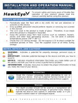
are shown in Fig. 2-1.
Fig. 2-1 Transducer Types
Most transducer types can measure the water depth. Some of the
transducers also have two other sensors: a paddle wheel which detects
the speed of the boat, and a sensor for the water temperature. The
display unit uses the speed information to calculate the distance the boat
has traveled.
The transducer is very important to the operation of the Fishfinder. It is
also important that you mount the transducer correctly. The transducer
Thru-hull
transducer
Fairing for
thru-hull transducer
Transom-mount
transducer
In-hull
transducer
Sidelooker
transducer
Low profile
transducer

Chapter 2: Installation
5
will give the most reliable readings if it looks into water which is smooth
and undisturbed. If you place the transducer so bubbles or turbulence
flow across the face of the unit, the system may give inaccurate
readings.
There are three important rules for placing any type of transducer:
• The transducer should be continuously covered by water when the
boat is moving. (If the transducer is mounted near the side of the
boat, it may be exposed when the boat is turning.)
• The transducer should be placed where turbulence or bubbles will not
pass directly over the face of the unit. Don’t place the transducer
behind any running strakes, intakes, or thru-hull fittings which create
turbulence.
• The transducer should be mounted where it will not be affected by the
wash from the propeller(s).
Selecting the Correct Type of Transducer
Before you begin the installation, double-check to be sure you have the
correct type of transducer. Each kind of transducer is designed for a
particular type of use. In this manual we will include detailed mounting
instructions for the thru-hull and transom-mount transducers. We will
also include some general information on the other types. For detailed
information on these other transducers, see the instructions which are
packaged with the unit.
Use a thru-hull transducer if –
. . . your boat has a straight-shaft inboard engine. This type of
transducer is installed in a hole drilled through the hull.
Use a transom-mount transducer if –
. . . your boat has an outboard or inboard-outboard engine(s) only. This
type of transducer must be mounted ahead of or beside the propeller(s).
Do not use this type of transducer for a boat with a straight-shaft inboard
engine.
Use an in-hull transducer if –
. . . you have a high-speed boat or if, for some reason, you cannot use a
transom-mount or thru-hull transducer. The hull may be no more than 1"
thick.

L750 Fishfinder: Installation and Operation Handbook
6
Use a trolling motor transducer if –
. . . you want to attach the transducer to a trolling motor.
Use a Sidelooker transducer if –
. . . you need a way of searching for fish on either side of the boat. This
type of transducer is attached to the bracket of the transom-mount
transducer.
Installing a Thru-Hull Transducer
This unit may be used with a thru-hull transducer. Please read this
section completely before starting the installation. Normally, this type of
installation is performed by a professional.
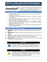
Fig. 2-2 Thru-Hull Transducer
2.00" dia.
(51 mm)
1.05"
(27 mm)
3.13" dia.
(79 mm)
5.24"
(133 mm)
5.50"
(140 mm)

Chapter 2: Installation
7
Before You Begin the Installation
Follow these instructions if you are installing the thru-hull transducer.
Here are some rules to remember:
• Do not install the thru-hull transducer, then leave your boat in the
water for any amount of time without checking for leaks.
• The position of the transducer is especially critical on high speed
vessels (capable of more than 20 knots). Check the locations of the
transducers on similar boats before installing the transducer on your
own boat. Choose the location which will offer the best performance.
• If the hull of your vessel has a core-type hull, you will need to follow
some special mounting procedures. (If the core material is allowed to
remain wet, it may rot and weaken the hull.) If you are in any doubt
about this kind of installation, consult your boat representative or your
Raymarine dealer.
A set of installation instructions will be packaged with each transducer.
These will give you more detailed information than we can include here.
The notes in this section will help you through the most important parts of
the installation process. (If the instructions in the package are different
from the notes in this manual, follow the packaged instructions.)
Selecting the Best Location for the Transducer
Follow these instructions if you are installing the thru-hull transducer.
Here are some important rules for mounting the transducer:
• For planing hulls – Install in the flat planing area near the stern.
Always install forward of the propeller(s) and shaft(s).
• For small displacement hulls – Install near the centerline of the hull
and 1/3 of the way forward from the stern. Always install forward of
the propeller(s) and shaft(s).
• For large displacement hulls – Install near the centerline of the hull
and 1/3 of the way aft from the bow. Always install forward of the
propeller(s) and shaft(s).
• For sailboats – Install forward of the leading edge of the keel, to one
side and near the centerline of the hull.
• Place the unit where bubbles will not pass over the front of the
transducer (especially at higher speeds). Avoid any bubbles caused
by shaft struts, fittings, or other transducers with paddle wheels. If you
notice any erosion of the paint on the hull, this is a sign of turbulence or
bubbles.

L750 Fishfinder: Installation and Operation Handbook
8
• Choose a location where the transducer will always be covered by
water.
• The beam from the transducer should not be blocked by a keel or
prop shaft.
• Choose a location where you can easily reach the transducer from
inside the vessel. This will allow you to make adjustments and
periodic inspections. Allow at least 6" (152 mm) of headroom above
the transducer.
• The “deadrise” is the angle or slope of the bottom of the hull in the
side-to-side direction. Try to find a mounting location with the smallest
deadrise angle.
Fig. 2-3 Best Transducer Locations
Mounting the Fairing Block
Follow these instructions if you are installing the thru-hull transducer.
The transducer should aim straight down (within 10°). If the bottom of
the hull is sloped more than this, a fairing block may be necessary to
Sailboats
Best locations for
thru hull
transducers
Tri-hulls
Planing hulls

Chapter 2: Installation
9
Inner part
of fairing
block
Outer part
of fairing
block
Lower part of
transducer
(front view)
Section
of hull
Upper part of
transducer
keep the transducer perpendicular to the waterline. A fairing block which
can adjust for angles of up to 25° is available from Raymarine.
1. Measure the deadrise angle of the hull at the selected mounting
point.
2. Cut the block to a shape which fits the exact contour of the hull. The
cut-out portion can be mounted inside the hull to provide additional
support for the transducer once it is mounted.
3. Attach the fairing block to the hull as firmly as possible. This fairing
block must be able to resist the drag of the water against the hull, and
must also be completely waterproof.
Fig. 2-4 Installing a Fairing Block

L750 Fishfinder: Installation and Operation Handbook
10
Installing a Thru-Hull Transducer
Follow these instructions if you are installing the thru-hull transducer.
Once you have decided where to install the transducer, drill the hole for
the part.
1. Begin by drilling a small pilot hole (1/8" or 3 mm) from the inside of
the hull. (This small hole can be filled easily if the mounting location
is not suitable.) Before you drill the hole, be sure you will be able to
reach the large nut on the top of the transducer, once it has been
mounted. Also be sure there will be enough clearance for the cable.
If there is a strake or other feature on the hull, drill from the outside of
the hull instead.
2. Drill a larger hole from the outside of the hull using a 2" (50 mm) hole
saw or paddle bit.
3. Uncoil the transducer cable. Remove the large hex nut from the
housing and slide it over the end of the cable.
4. Thread the cable through the hole to the inside of the hull. Never pull
or carry the transducer using the transducer cable. This may break
the wiring connections inside the cable. Never hold the transducer in
place by pulling on the transducer cable.
5. Apply a thin layer of sealant (1/8" or 3 mm) to the transducer
between the upper flat surface of the transducer and the fairing
block. Use a high-quality marine sealant suitable for underwater
use. Also apply a thin layer up the side walls. This should cover all of
the threads where the part will touch the hull material, plus an
additional 1/4" (6 mm). This will seal the threads for the large hex
nut.
6. Push the transducer housing (with the sealant applied) into the hole
from the outside of the hull. Twist the housing slightly to squeeze out
any excess sealant and to get a good seal. Be sure that the
transducer is aligned so that the correct part of the unit is toward the
bow of the vessel. See Fig. 2-5. Hold or prop the transducer in place
temporarily.
7. Go to the inside of the hull and slide the hex nut over the end of the
cable. Fit the hex nut over the end of the transducer and tighten it.
(On a vessel with a wooden hull, do not tighten the nut completely
right away. Allow some time for the wood to swell after the vessel is
put in the water.
8. Remove any excess sealant from the outside of the unit to assure
smooth water flow over the transducer.

Chapter 2: Installation
11
9. As soon as the boat is placed in the water, check for leaks. Check
again within 3 to 5 hours. (You may not be able to see a small leak
right away.) If there are any leaks, you must repeat the installation
procedure.
Fig. 2-5 Mounting the Transducer Correctly
Assembling the Transducer Bracket
Follow these instructions if you are installing the transom-mount
transducer.
Fit together the two parts of the transducer bracket as shown in Fig. 2-6.
When the installation is complete, the parts snap together as shown.
Fig. 2-6 Assembling the Transducer Bracket
This end forward
Paddle wheel
assembly near
rear.
Lower the transducer
and snap in the
release clip
Attach the
two parts
Bracket is installed
upside down
NOT THIS!LIKE THIS!
/