Page is loading ...

Distributed by
Any reference to Raytheon or
RTN in this manual should be
interpreted as Raymarine.
The names Raytheon and RTN
are owned by the
Raytheon Company.


Echo Sounding
How it Works
◆ Your eyes underwater
An “echo sounder” or “sonar” unit sends high-frequency sound waves down into the
water below a boat. These sounds hit the bottom of the lake or sea and bounce back.
The display unit measures the time delay as the signal goes out and returns. The
FishFinder uses this information to display a graphic image of the bottom conditions.
The system also uses this same principle to detect fish or other objects in the water,
and display their size and location. This display is like a “window” which allows you to
look into the underwater world.
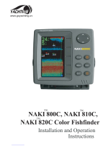
◆ About the transducer
The transducer transmits the sound waves down into the
water. It also receives the waves as they return. One
type of transducer can be mounted on the transom
of the boat, as shown here. Other types of
transducers can be installed through a hole in
the hull, or mounted inside the hull.
◆ The Sidelooker
transducer
The optional Sidelooker is a
special type of transducer
which allows the Fish-
Finder to detect fish beside
the boat. The Sidelooker
produces two powerful hori-
zontal beams which ex-
tend to either side, just
below the surface of the
water.
The Sidelooker transducer uses a
special plastic material called “PVDF,”
which was developed by Raytheon
Naval Systems. This allows the Side-
looker to give you the clearest possible
picture of conditions underwater.

“Out of the box” operation
Because of a number of automatic fea-
tures, the FishFinder 465 unit is ready to
operate “right out of the box.” This unit in-
cludes automatic settings for the most
important controls – range, sensitivity, and
zoom. Because these settings are
automatic, the FishFinder will provide use-
ful displays right from the start. Once you
become more comfortable with the
operation of the unit, you can adjust these
settings.
Excellent ability to find fish
To a sonar unit like the FishFinder, the
water includes a lot of background “noise.”
There are many conditions which could
confuse a sonar unit – bubbles and wakes
in the water, temperature differences be-
tween water layers, and so on. It can be
difficult for a sonar unit to detect fish
against this background of noise.
Because of its advanced circuitry, the 465
is especially good at telling the difference.
Dual frequency operation
“Frequency” is a measure of how fast the
sound waves change or “vibrate.” The
FishFinder uses sound waves with two
different frequencies – 50 kHz and 200
kHz. The 50 kHz frequency scans a wide
area, and penetrates the water well. This
frequency is best for use in deep water.
The 200 kHz frequency scans a narrower
area but produces a more detailed view.
This frequency is best for seeing fish near
the bottom, or fish which are close
together. The FishFinder can also use
both frequencies at the same time. This
provides good depth penetration and good
detail in the display.
FishFinder 465
Features and functions
Fish symbols and alarms
The unit provides fast, positive identifica-
tion of fish in the water. It even indicates
the size of a fish using eight different fish
symbols. The 465 includes alarms for
shallow warning, deep warning and fish
warning.
Clear LCD display
The FishFinder display produces continu-
ous pictures of bottom conditions and fish
in the water. The display unit may be
turned or tilted to the best viewing angle.
The FishFinder unit can be easily
removed from the boat for storage in a
safe place.
Totally waterproof
The FishFinder 465 meets U.S. Coast
Guard specifications for waterproofing, so
it can stand up to the hard service
required on small boats. The rugged
construction and sophisticated sealing
methods used in this unit will ensure
many years of reliable service.
PWR
SETUP
CLEAR
465
ZOOM
BOT
LOCK
A-SCP
FISHFINDER

Before you begin
This manual contains very important information on the installation and
operation of your FishFinder 465. For best results as you use this unit,
please take the time to read this manual thoroughly.
IMPORTANT NOTICE
THIS DEVICE IS ONLY AN AID TO NAVIGATION. ITS ACCURACY CAN
BE AFFECTED BY MANY FACTORS, INCLUDING EQUIPMENT
FAILURE, DEFECTS, ENVIRONMENTAL CONDITIONS AND IM-
PROPER HANDLING OR USE.
IT IS THE USER’S RESPONSIBILITY TO EXERCISE COMMON PRU-
DENCE AND NAVIGATIONAL JUDGMENT. THIS DEVICE SHOULD
NOT BE RELIED UPON AS A SUBSTITUTE FOR SUCH PRUDENCE
AND JUDGMENT.
Warranty card
Before you go any further, please take a few minutes to fill out the
warranty card. It is very important that you return the warranty card soon
after your purchase. This will ensure that you receive the full benefits
offered by the warranty.
Service information
In the unlikely event that your unit is ever in need of service, please refer
to the section on “Maintenance and Troubleshooting” at the back of this
manual. See the information on “How to Contact Apelco.”
Special terms
In this manual, we will use some special terms which have to do with
boats and boating. These are explained in a Glossary at the end of the
manual. If you do not recognize a word which appears in this manual,
check the Glossary.
ii

FishFinder 465
Instruction Manual

iv
Contents
Echo sounding – How it works (inside front cover)
FishFinder 465 – Features and functions i
For information and service ii
1 Introduction 1
About the FishFinder 465 1
System Components 2
Standard Equipment 2
Standard Transducers 2
Optional Accessories 2
2 Installation 4
About the Transducer 4
Selecting the Correct Type of Transducer 5
Assembling the Transducer Bracket 6
Positioning the Transom-Mount Transducer 6
Mounting the Transom-Mount Transducer 9
Mounting the Optional Sidelooker Transducer 10
Installation Notes – Thru-Hull Transducer 10
Installation Notes – In-Hull Transducer 12
Installation Notes – Trolling Motor Transducer 12
Installation Notes –
Transducer for Speed and Temperature Only 13
EMC Installation Guidelines 13
Mounting the Display Unit – Standard Mount 15
Mounting the Display Unit – Flush Mount 17
Installing the Transducer Cable 18
Installing the Transducer Cable – Sidelooker Option 20
Installing the Transducer Cable –
Separate Speed and Temperature Sensors 20
Making the DC Power Connections 21
Calibrating the Sensors 23
3 Operating Instructions 25
Controls on Display Unit 25
Turning the Power On and Off 27
Setup Memory 27
Lamp/Contrast Display 28

v
Operating Pages 29
FishFinder Page 31
Choosing a Frequency 36
Fish Indications 37
Bottom Indications 38
Window Page 40
Sidelooker Page 42
Digital Page 46
Performance Modes 49
Zoom Mode 49
A-Scope (Bottom Coverage) Mode 51
Bottom Lock Mode 53
4 Setup Instructions 55
The Setup Menu 55
Range Setting 56
Sensitivity Setting 57
Chart Speed Setting 59
Frequency Setting 60
Resetting the Log 62
System Setup Menu 63
Simulator 64
Language 64
Fish Symbol 64
White Line 64
VRM 65
Sidelooker 65
Speed Cal 65
Temp Cal 66
Depth Digits 66
Shallow Alarm 66
Deep Alarm 67
Fish Alarm 67
Buzzer 68
Depth Units 69
Speed Units 69
Temp Units 69
Speed 69
Log 69
Temp 69
Setup Menus for Zoom Mode 70
Zoom Select Menu 70
Zoom Screen Split/Full Menu Item 71
Setup Menus for Bottom Lock Mode 72
Bottom Lock Range Menu Item 72
Bottom Lock Split/Full Menu Item 73
Setup Menu for Window and Digital Pages 74
Resetting from the Digital Page 75
Setup Instructions for Sidelooker 75
Sidelooker Range Menu Item 76

vi
Sidelooker Sensitivity Menu Item 77
Sidelooker Chart Speed Menu Item 77
Sidelooker View Menu item 78
Combining Displays 79
Resetting the Unit to Factory Defaults 80
Default Settings 81
5 Maintenance and Troubleshooting 82
Cleaning Instructions 82
Troubleshooting Suggestions 82
Servicing a Thru-Hull Transducer 86
How to Contact Apelco 86
6 Specifications 89
General Information 89
FishFinder Functions 90
Connector Diagrams 91
Glossary of Terms 92

vii
List of Figures
Figure Page
Unit in Use Inside front cover
Front Panel i
1-1 Typical Installation 1
2-1 Transducer Types 5
2-2 Assembling the Transducer Bracket 6
2-3 Transducer Mounted on Transom 7
2-4 Transducer Bracket, Side View 7
2-5 Correct Mounting Position 8
2-6 Mounting the Transducer 8
2-7 Installing the Sidelooker Transducer 10
2-8 Suppression Ferrites 14
2-9 Installation on Bracket 15
2-10 Dimensions 16
2-11 Flush-Mount Installation 17
2-12 Disassembling from Bracket 18
2-13 Installing Cable on Transom 19
2-14 Cable for Sidelooker Transducer 20
2-15 Cable for Speed and Temperature Sensor 21
2-16 DC Power Connections 22
3-1 Display Panel 25
3-2 Lamp/Contrast Menu 28
3-3 Operating Pages 30
3-4 FishFinder Mode Page 31
3-5 Fish Indications 37
3-6 Bottom Conditions 39
3-7 Window Page 40
3-8 Options for Window Page 41
3-9 Sidelooker Feature 42
3-10 Sidelooker Page 43
3-11 Digital Page 46
3-12 Performance Modes 48
3-13 Zoom Mode 49
3-14 A-Scope Mode 51
3-15 Bottom Lock Mode 53
4-1 Setup Menu Items 55
4-2 Range Menu Item 56
4-3 Sensitivity Menu Item 57
4-4 Changing the Chart Speed Setting 59
4-5 Chart Speed Menu Item 60
4-6 Frequency Menu Item 60
4-7 Log Reset Menu Item 62

viii
4-8 Reaching the System Setup Menu 63
4-9 System Setup Menu 63
4-10 Zoom Select Menu Item 70
4-11 Zoom Screen Split/Full Menu Item 71
4-12 Bottom Lock Range Menu Item 72
4-13 Bottom Lock Split/Full Menu Item 73
4-14 Digital Setup Menu Item 74
4-15 Sidelooker Range Menu item 76
4-16 Sidelooker Sensitivity Menu Item 77
4-17 Sidelooker Chart Speed Menu Item 77
4-18 Sidelooker View Menu Item 78
4-19 Split FishFinder Page with A-Scope Mode 79
4-20 Window Page with Option G Selected
and Zoom Enabled 80
5-1 Sample Mailing Label 88
6-1 Connector Diagrams 91

1
Introduction
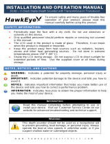
Fig. 1-1
Typical Installation
1 – Introduction
About the FishFinder 465
The FishFinder 465 is a system that uses sound waves (“sonar”) to
detect fish and show the bottom of a lake or sea. The system includes a
transducer and a display unit, connected by a cable. The transducer
sends high-frequency sound waves down into the water. These sounds
strike fish, the bottom, or other objects in the water, and return as
echoes. The FishFinder then interprets these echoes and presents a
display.
The FishFinder 465 can handle many different jobs:
• detect the presence of fish below the boat
• trigger an alarm when fish are found
• measure the depth of the water
• set alarms for minimum and maximum depth
• show the shape of the bottom
• determine whether the seabed is hard or soft
• measure the speed of the boat and the distance traveled
• show the water temperature
We are sure you will find the FishFinder 465 to be one of the most useful
devices on your boat.
FishFinder 465
Display Unit
Optional Thru Hull
Transducer
Transducer mounted
in quick release
transom bracket
PWR
SETUP
CLEAR
465
ZOOM
BOT
LOCK
A-SCP
FISHFINDER

2
Introduction
System Components
The FishFinder 465 consists of a compact display unit connected to a
transducer. The transducer is attached to the boat and extends into the
water.
Standard Equipment
When you unpack your FishFinder 465, you should find the following
standard equipment in the carton. If any items are missing, please notify
your Apelco dealer immediately, or contact the Customer Service
Department at Apelco at 1-800-539-5539, ext. 2120. Please provide the
serial number of the FishFinder when reporting any missing items.
Description Part No.
FishFinder 465 display unit M78954
Quick-release swivel-mount bracket
(with mounting hardware) G623996-1
DC power cable M99-146
Instruction manual 81146-1
Four #10 x 3/4” ss mounting screws —
Standard Transducers
Depending on which model of the 465 you have purchased, the box will
include one of the transducers listed below:
Description Part No.
Transom-mount transducer (with speed
and temperature sensors, including
mounting bracket and hardware) M78898
Bronze thru-hull transducer (with
speed and temperature sensors) M78923
Optional Accessories
Optional accessories and parts can be purchased directly from Apelco
Marine. For prices and ordering information, please call the Parts
Department at (800) 539-5539 ext. 2120.

3
Introduction
Description Part No.
Sidelooker transom-mount transducer M78930
Sidelooker transducer for trolling motor
(all-in-one unit senses depth below boat,
with Sidelooker and temperature sensor,
including mounting hardware) M78929
Extension for transducer cable (15 ft., 5 m) M99-140
Extension for transducer cable,
for Sidelooker transducer (15 ft., 5 m) M99-139
Flush-mounting kit (with hardware and
mounting template) M99-138
Fairing block for M78923 thru-hull
transducer (Lexan
®
) M99-142
Low profile plastic thru-hull transducer
(Valox
®
plastic, sensor for depth only) M78922
Bronze thru-hull transducer
(sensor for depth only) M78921
In-hull/trolling motor transducer (for installation in
fiberglass hull only, or mounting on trolling motor,
including hardware for either installation) M78928
Angled in-hull transducer (for installation
in fiberglass hull only, where deadrise
angle is 10° to 22°) M78946
Plastic thru-hull transducer (Valox® plastic, with
speed and temperature sensors, used with depth-
only transducers M78922, M78928, M78946) M78937
Transom-mount speed and temperature
sensor (used with depth-only transducers
M78922, M78928, M78946) M78936
Replacement transom transducer
mounting bracket kit M99-148
Transducer switch box (select between two 465
FishFinder displays, using one transducer) M99-136
Replacement paddle wheel kit (for transom-
mount transducer) M99-143
Replacement paddle wheel kit
(for thru-hull transducer) D234
Replacement paddle wheel kit
(for bronze thru-hull transducer) D144

4
Installation
2 – Installation
The installation process has four parts:
• Mounting the transducer
• Mounting the display unit
• Connecting the cables for the transducer and power supply
• Calibrating the display unit
About the Transducer
Several different kinds of transducers can be used with this unit. The
transom-mount type is used most often. Other types are shown in Fig. 2-
1.
Most transducer types can measure the water depth. Some of the
transducers also have two other sensors: a paddle wheel which detects
the speed of the boat, and a sensor for the water temperature. The
display unit uses the speed information to calculate the distance the boat
has traveled.
The transducer is very important to the operation of the FishFinder. It is
also important that you mount the transducer correctly. The transducer
will give the most reliable readings if it looks into water which is smooth
and undisturbed. If you place the transducer so bubbles or turbulence
flow across the face of the unit, the system may give inaccurate readings.
There are three important rules for placing any type of transducer:
• The transducer should be continuously covered by water when the
boat is moving. (If the transducer is mounted near the side of the
boat, it may be exposed when the boat is turning.)
• The transducer should be placed where turbulence or bubbles will
not pass directly over the face of the unit. Don’t place the transducer
behind any running strakes, intakes, or thru-hull fittings which create
turbulence.
• The transducer should be mounted where it will not be affected by
the wash from the propeller(s).

5
Installation
Transom-mount
transducer
Thru-hull
transducer
In-hull
transducer
Sidelooker
transducer
Fairing for
thru-hull transducer
Fig. 2-1
Transducer
Types
Selecting the Correct Type of Transducer
Before you begin the installation, double-check to be sure you have the
correct type of transducer. Each kind of transducer is designed for a
particular type of use. In this manual we will include detailed mounting
instructions for the transom-mount transducer. We will also include some
general information on the other types. For detailed information on these
other transducers, see the instructions which are packaged with the unit.
Use a transom-mount transducer if –
your boat has an outboard or inboard-outboard engine(s) only. This type
of transducer must be mounted ahead of or beside the propeller(s). Don’t
use this type of transducer on a boat with a straight-shaft inboard engine.
Use a thru-hull transducer if –
your boat has a straight-shaft inboard engine. This type of transducer is
installed in a hole drilled through the hull.
Use an in-hull transducer if –
you have a high-speed boat or if, for some reason, you cannot use a
transom-mount or thru-hull transducer. The hull may be no more than 1"
thick.

6
Installation
Lower the transducer
and snap in the
release clip
Attach the
two parts
Bracket is installed
upside down
NOT THIS!LIKE THIS!
Fig. 2-2
Assembling
the Transducer
Bracket
Use a trolling motor transducer if –
you want to attach the transducer to a trolling motor.
Use a Sidelooker transducer if –
you need a way of searching for fish on either side of the boat. This type
of transducer is attached to the bracket of the transom-mount transducer.
Assembling the Transducer Bracket
Fit together the two parts of the transducer bracket as shown in Fig. 2-2.
When the installation is complete, the parts snap together as shown.
Positioning the Transom-Mount Transducer
Begin by finding the best location for the mounting bracket. Here are the
rules:
• If your boat has one propeller (outboard or inboard-outboard), mount
the transducer about 18” (455 mm) to the side of the centerline of
the boat. See Fig. 2-3. Choose the side that is on the downstroke of
the propeller. (This is usually the starboard side of the boat.) This
will reduce any interference caused by air bubbles.
• If your boat has twin propellers (outboard or inboard-outboard),
place the transducer near the centerline of the boat.
• If the propeller can be turned to steer the boat, allow at least 2" (50
mm) beyond the swing radius of the propeller. This will prevent the

7
Installation
Fig. 2-3
Transducer
Mounted on
Transom
Transducer in
released position
10"
(254 mm)
Allow a clearance
of at least 10
inches (254 mm)
Fig. 2-4
Transducer
Bracket,
Side View
propeller from damaging the transducer when it is turned.
•
Do not
mount the transducer behind any hull fittings, intakes, or
other parts which extend from the hull. These may cause turbulence
or air bubbles.
• The bracket has a quick-release mechanism. This prevents damage
by allowing the transducer to flip up if it hits any debris or the bottom.
See Fig. 2-4. Allow enough clearance above the transducer so that it
can swing upward completely. This is about 10" (254 mm) measured
from the bottom of the transom.

8
Installation
123
Insert screws 1 and 3
1/4" from the bottom of
slots, and screw 2
1/4" from the top of the
slot to allow room for
adjustment.
Correct
alignment
If screws are inserted
this way, it won’t be
possible to make the
height adjustment.
Incorrect
alignment
Fig. 2-6
Mounting
the Transducer
Fig. 2-5
Correct Mounting
Position
Vertical transom –
place wedge this way
Average transom angle–
no wedge necessary
Sloping transom–
place wedge this way
For fiberglass hull – 1/8" to 1/4" (3.2 to 6 mm)
For aluminum hull – 1/4" to 3/8" (6 to 9 mm)
Rivets on the hull are
creating bubbles.
Lower the transducer
a bit.
The bow of the transducer
is above the bottom of the
transom, creating
cavitation.
The rear of the transducer
is too high, creating
cavitation.
2° to 5°
2° to 5° 2° to 5°
No! No! No!

9
Installation
• If the boat will be carried on a trailer, be sure the transducer will not
hit any rollers, bunks or fittings on the trailer.
Mounting the Transom-Mount Transducer
1. On a boat with a fiberglass hull, the leading edge of the transducer
should extend 1/8" (3.2 mm) to 1/4" (6 mm) below the bottom edge
of the hull. See Fig. 2-5. On an aluminum hull, the transducer should
extend a bit more – 1/4" (6 mm) to 3/8" (9 mm). If the boat will be
operated at high speeds, the transducer may be mounted closer to
the centerline of the hull.
2. The lower surface of the transducer should tilt down toward the rear
at a slight angle (2° to 5°). The mounting bracket includes a wedge.
Depending on the angle of the transom on your boat, you may need
this wedge to get the correct angle for the bottom of the transducer.
3. Looking at the rear of the boat, be sure the bracket is vertical
(perpendicular to the water line).
4. Hold the bracket (and the wedge, if used) against the transom and
trace the positions of the screw slots.
5. Remove the bracket. See Fig. 2-6. The screws in the outer slots
should be placed about 1/4" (6 mm) up from the bottom of each slot.
The screw in the center slot should be placed 1/4” (6 mm) down from
the top. (This will allow you to adjust the bracket up or down a bit.)
Drill pilot holes 3/4" (19.1 mm) deep. Use a 9/64" (3.6 mm) drill bit.
To prevent drilling too deeply, wrap masking tape around the drill bit
about 7/8" (22 mm) from the tip. Drill in only as far as the tape
marker.
If you are attaching the bracket to a fiberglass hull, you can minimize
any surface cracking of the gel coat. Before drilling each pilot hole,
drill a shallow hole (chamfer) at each location about 1/16" (1.5 mm)
deep. Use a 1/4" (6 mm) drill bit.
6. Attach the bracket to the hull using the panhead screws with flat
washers. Before you tighten the screws, apply a good-quality marine
sealant to the pilot holes. This will protect the hull from water
penetration.
Do not tighten the screws completely yet.
7. Move the bracket up or down so that the leading edge of the
transducer has the clearance shown in Fig. 2-5.
8. Once the bracket is in the correct position, you can tighten the screws.
/