Page is loading ...

DSM300
Digital Sounder
Module
Installation Manual
Document number: 87048-1
Date: November 2004

Trademarks and registered trademarks
HSB, Raymarine and SeaTalk are registered trademarks of Raymarine Limited.
All other product names are trademarks or registered trademarks of their
respective owners.
Contents of this handbook ©Raymarine 2004

3
Contents
Preface .....................................................................................................................5
Purpose .................................................................................................. 5
SAFETY NOTICE ...................................................................................... 5
EMC Conformance ................................................................................. 6
Conventions ........................................................................................... 6
Technical Accuracy ................................................................................. 6
Warranty ................................................................................................ 6
Chapter 1: DSM300 Installation ..........................................................................7
1.1 Introduction ........................................................................................... 7
Planning the Installation ........................................................................ 7
EMC Installation Guidelines ................................................................... 7
1.2 Unpacking and Inspecting the Components ........................................... 9
1.3 Selecting Sounder Module Mounting Location .................................... 10
1.4 Mounting the Sounder Module ............................................................ 11
1.5 Cable Runs ........................................................................................... 14
1.6 System Connections ............................................................................. 15
DC Power Connection .......................................................................... 15
Transducer Connection ........................................................................ 17
Ground Connection .............................................................................. 17
1.7 Configuration ....................................................................................... 20
Chapter 2: Transducer Installation ...................................................................23
2.1 Selecting the Correct Type of Transducer .............................................. 23
Applications ......................................................................................... 23
Accessories .......................................................................................... 25
2.2 Transducer Cable .................................................................................. 26
Transducer Cable Connections ............................................................. 26
2.3 Selecting the Equipment Location ........................................................ 29
Transducer Mounting Location ............................................................. 29
Transom Mount Transducer .................................................................. 30
2.4 Installing the Transom Mount Transducer ............................................ 35
Preparation .......................................................................................... 35
Installation ........................................................................................... 36
2.5 Installing the Thru-hull Transducer ....................................................... 36
Tools and Material Needed .................................................................. 36
Preparation .......................................................................................... 37
Installation ........................................................................................... 41
Drilling Holes ........................................................................................ 41
Installation in a Cored Fiberglass Hull .................................................. 48
2.6 Installing the In-hull Transducer ........................................................... 50
Tools and Material Needed .................................................................. 50

4 DSM300 Installation Manual
Testing the Selected Mounting Location ...............................................50
Installation ...........................................................................................52
Installation in a Cored Fiberglass Hull ...................................................55
Chapter 3: Maintenance and Problem Solving ...............................................57
3.1 Maintenance ........................................................................................57
Routine Checks .....................................................................................57
Cleaning Instructions ............................................................................57
EMC Servicing and Safety Guidelines ...................................................58
3.2 Resetting the System ............................................................................59
3.3 Problem Solving ...................................................................................61
Common Problems and Their Solutions ................................................61
Status LED ............................................................................................62
3.4 How to Contact Raymarine ...................................................................64
On the Internet .....................................................................................64
In the US ...............................................................................................64
In Europe ..............................................................................................66
Worldwide Support ..............................................................................66
Appendix A: Specifications...............................................................................67
General .................................................................................................67
Sounder Features ..................................................................................67
Index ......................................................................................... 69

5
Preface
Purpose
Raymarine DSM300 Digital Sounder Modules provide echo sounder data that can
be displayed on Raymarine E Series, C Series, and hsb
2
PLUS (Pathfinder) Series
display units.
DSM300 Digital Sounder Modules are intended for recreational depth finding and
fishfinding purposes. Echo sounder systems require an appropriate Raymarine
transducer unit and inter-connecting cable.
This manual contains very important information for installing your DSM300 and
transducer. To obtain the best results in operation and performance, please read
this handbook thoroughly. Raymarine’s Technical Services representatives or your
local dealer will be available to answer any questions you may have.
SAFETY NOTICE
This equipment must be installed and operated in accordance with the
instructions contained in this manual. Failure to do so can result in personal injury
and/or navigational inaccuracies. In particular:
CAUTION: High Voltage
The DSM300 contains high voltages. Adjustments require specialized service
procedures and tools only available to qualified service technicians – there are no
user serviceable parts or adjustments. The operator should never remove the
cover or attempt to service the equipment.
CAUTION: Transducer Cable
Removing the transducer cable from the rear of the DSM300 while the sounder
module is powered on can cause sparks. Only remove the transducer cable after
power has been removed from the DSM300. As with any electronic device, be
sure the sounder module is mounted where it is well ventilated and free from
gasoline fumes.
If the transducer cable is accidentally removed while the DSM300 is powered on,
remove power from the sounder module, replace the transducer cable, and then
return power to the module. As a safety feature, the DSM300 only recognizes that
the transducer is connected at power-up.

6 DSM300 Installation Manual
EMC Conformance
All Raymarine equipment and accessories are designed to the best industry
standards for use in the recreational marine environment.
The design and manufacture of Raymarine equipment and accessories conform to
the appropriate Electromagnetic Compatibility (EMC) standards, but correct
installation is required to ensure that performance is not compromised.
Conventions
Throughout this handbook, the dedicated (labelled) keys are shown in bold
capitals; for example, ENTER. The soft key functions, menu names and options
are shown in normal capitals; for example, SCREEN.
Operating procedures, which may consist of a single key-press or a sequence of
numbered steps, are indicated by a ➤ symbol in the margin. When the procedure
requires you to press a soft key, the soft key icon is shown in the margin.
Technical Accuracy
To the best of our knowledge, the technical and graphical information contained
in this handbook was correct as it went to press. However, the Raymarine policy of
continuous improvement and updating may change product specifications
without prior notice. As a result, unavoidable differences between the product
and handbook may occur from time to time, for which liability cannot be accepted
by Raymarine.
Warranty
To register your DSM300 Digital Sounder Module ownership, please take a few
minutes to fill out the warranty registration card found at the end of this
handbook. It is very important that you complete the owner information and
return the card to the factory in order to receive full warranty benefits.

7
Chapter 1: DSM300 Installation
1.1 Introduction
This chapter provides details for mounting the DSM300 and connecting to the
display.
For the system to display depth, water temperature and speed, you must install
the transducer type(s) capable of transmitting the appropriate data. Transducer
information is provided in Chapter 2.
Planning the Installation
Before you install your system, plan the installation, considering:
• Correct transducer for your application, as described in Section 2.1
• Location of the sounder module, as described in Section 1.3
• Cable Runs, as described in Section 1.5
EMC Installation Guidelines
All Raymarine equipment and accessories are designed to the best industry
standards for use in the recreational marine environment.
Their design and manufacture conforms to the appropriate Electromagnetic
Compatibility (EMC) standards, but correct installation is required to ensure that
performance is not compromised. Although every effort has been taken to ensure
that they will perform under all conditions, it is important to understand what
factors could affect the operation of the product.
The guidelines given here describe the conditions for optimum EMC performance,
but it is recognized that it may not be possible to meet all of these conditions in all
situations. To ensure the best possible conditions for EMC performance within the
constraints imposed by any location, always ensure the maximum separation
possible between different items of electrical equipment.
For optimum EMC performance, it is recommended that wherever possible:
• Raymarine equipment and cables connected to it are:
• At least 5 ft (1.5 m) from any equipment transmitting or cables carrying
radio signals, e.g., VHF radios, cables and antennas. In the case of SSB
radios, the distance should be increased to 7 ft (2 m).

8 DSM300 Installation Manual
• More than 7 ft (2 m) from the path of a radar beam. A radar beam can nor-
mally be assumed to spread 20 degrees above and below the radiating
element.
• The equipment is supplied from a separate battery from that used for engine
start. Voltage drops below 10 V and starter motor transients can cause the
equipment to reset.
This will not damage the equipment, but may cause the loss of some informa-
tion and may change the operating mode.
• Raymarine specified cables are used. Cutting and rejoining these cables can
compromise EMC performance and must be avoided unless doing so is
detailed in the installation manual.
• If a suppression ferrite is attached to a cable, this ferrite should not be
removed. If the ferrite needs to be removed during installation it must be reas-
sembled in the same position.
Suppression Ferrites
The following illustration shows typical cable suppression ferrites used with
Raymarine equipment. Always use the ferrites supplied by Raymarine.
Figure 1-1: Typical Suppression Ferrites
Connections to Other Equipment
If your Raymarine equipment is to be connected to other equipment using a cable
not supplied by Raymarine, a suppression ferrite must always be attached to the
cable that is closest to the Raymarine unit.

Chapter 1: DSM300 Installation 9
1.2 Unpacking and Inspecting the Components
Unpack your system carefully, to prevent damage to the equipment. Save the
carton and packing, in case you need to return the unit for service.
Check that you have all the correct system components:
A 3m-long cable is included for connecting your DSM300 to a C Series display.
Longer cables and connection cables for other types of systems must be
purchased separately. Select from the following:
Table 1-1: Cable Options
System Item Part No.
E Series
SeaTalk
hs
Network Cable, RJ-45, 1.5m
SeaTalk
hs
Network Cable, RJ-45, 5m
SeaTalk
hs
Network Cable, RJ-45, 10m
SeaTalk
hs
Network Cable, RJ-45, 20m
E55049
E55050
E55051
E55052
C Series C Series Network Cable, 4-pin-to-4-pin, 10m
DSM Cable, 4-pin-to-3-pin, 3m
DSM Cable, 4-pin-to-3-pin, 10m
E65011
E65009
E05016
hsb
2
PLUS Series
(Pathfinder)
hsb
2
In Line Terminator
hsb
2
Splitter Cable
R58117
E55040
Power Cable, 3m
part no. R69053
Mounting Screws,
No.8 (x4)
Operation Manual for PLUS
Displays, part no. 81249
D7481-1
Installation Manual,
part no. 87048
Digital Sounder Module,
part no. E63069
C Series Network Cable, 3m
part no. E65010
hsb
2
adapter, 4-pin to 3-pin
part no. R69081
DSM300
Installation
Manual
DSM300
Operation
Manual

10 DSM300 Installation Manual
1.3 Selecting Sounder Module Mounting Location
The DSM300 is waterproof to IPX-7 is and is designed to be mounted either above
or below deck.
Mount the DSM300 where it is:
• protected from physical damage and excessive vibration
• protected from prolonged exposure to rain, salt spray and direct sunlight
• well ventilated
• as close to the transducer as possible
Do not locate the DSM300:
• in the engine compartment
• on the main console
When planning the installation, the following should be considered to ensure
reliable and trouble free operation:
•
Access: There must be sufficient space below the unit to enable cable con-
nections to the panel connectors, avoiding tight bends in the cable.
•
Interference: The selected location should be far enough away from
devices that may cause interference, such as motors, generators, and radio
transmitter/receivers. (See the EMC guidelines earlier in this chapter.)
•
Magnetic compass: Mount the unit at least 3 ft (1 m) away from a magnetic
compass.
•
Cable runs: The unit must be located near a DC power source. The power
cable supplied is 10 ft (3 m).
•
Environment: Good ventilation is required to prevent the unit from over-
heating.
CAUTION: Do Not Remove the Transducer Cable
Removing the transducer cable from the DSM300 while power is
turned on can cause sparks. As with any electronic device, be sure
the sounder module is mounted where it is well ventilated and
free from gasoline fumes.

Chapter 1: DSM300 Installation 11
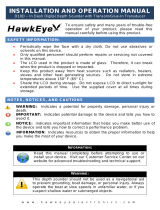
1.4 Mounting the Sounder Module
The DSM300 can be mounted either above or below deck using the supplied
hardware. To allow for ease of cable connection, mount the sounder module so
that the cables hang below the unit.
Figure 1-2: DSM300 Dimensions
➤ To mount the DSM300:
1. Hold the module in the location where you want to mount it, making sure it is
perpendicular to the deck.
2. Mark the location of the four key holes onto the mounting surface.
9.96 in (252.9 mm)
D7468-1
3.46 in
(88 mm)
9.51 in (241.6 mm)
10.76 in (273.3 mm)
7.37 in (187.2 mm)
Weight: 2.2 lbs (1.0 Kg)
Compass Safe Distance: 39 in (1 m)
2.43 in
(61.7 mm)
1.65 in
(41.8 mm)

12 DSM300 Installation Manual
3. Drill a 9/64" pilot hole at each of the marked locations.
Note:
For fiberglass with a gelcoat surface, you should overdrill the surface to prevent the
gelcoat from chipping when driving in the screw. Before drilling the pilot hole, hand drill
the marked location with an oversized bit and countersink to approximately 3/8" diame-
ter.
4. Drive the supplied #8 screws into the pilot holes. Screw them in about half way.
5. Mount the module to the surface, slipping the screw heads through the four
key holes.
Vertical
x4
D7479-1
Vertical
x4
D7538-1

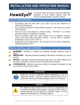
Chapter 1: DSM300 Installation 13
6. Press the module downward so the screws align with the narrow end of the
keyholes.
7. Tighten the screws. Do not overtighten.
Figure 1-3: Properly Mounted DSM300
1
2
3
6 mm
minimum
D7480-1
7469-1

14 DSM300 Installation Manual
1.5 Cable Runs
Consider the following before installing the system cables:
• You will need to attach power, transducer, and display cables.
• All cables should be adequately secured, protected from physical damage,
and protected from exposure to heat.
• Avoid running cables through bilges or doorways, or close to moving or hot
objects.
• Avoid sharp bends.
• Use a watertight feed-through wherever a cable passes through an exposed
bulkhead or deckhead.
• Secure cables in place using tie-wraps or lacing twine. Coil any extra cable
and tie it out of the way.
You will need to run the following cables:
•
Power cable, supplied with the unit. This 10 ft (3 m) cable has a connector
plug at one end for connecting to the sounder module, and 3 wires at the other
end for connecting the power supply. The power cable may be extended by up
to 60 ft (20 m) using a wire gauge of AWG 12 or greater. The DSM300 is
intended for use on boat’s DC power systems rated from 10.7 V to 32 V.
•
Display cable, used to connect the DSM300 to a display unit. A 3m-long
cable is included for connecting to a C Series display. Connection cables for E
Series or hsb
2
PLUS (Pathfinder) Series displays, or longer C Series cables, must
be purchased separately. See Table 1-1 “Cable Options“ on page 9 for a list of
available display cables.
•
Transducer cable, supplied with the transducer. This 30 ft (10 m) cable has
a connector plug (with an outer nut that you must attach) at one end for the
sounder module or extension cable. Optional extension cables are listed in
Table 2-1 “Accessories“ on page 25.
CAUTION: Do Not Cut or Splice the Transducer Cable
• There is high voltage on the transducer cable. Splicing could
create a safety hazard.
• Cutting the transducer cable severely reduces sonar
performance. If the cable is cut, it must be replaced—it cannot
be repaired.
• Cutting the transducer cable will void the warranty and
invalidate the European CE mark.

Chapter 1: DSM300 Installation 15
1.6 System Connections
The connector panel provides the following connection sockets:
•
T/D, 7-pin socket for connecting to the transducer
•
HSB2, 4-pin socket for connecting to a C Series or hsb
2
PLUS Series display
•
POWER, 3-pin socket for connecting to boat’s DC power systems rated from
10.7 V to 32 V and one RF ground (screen) connection
•
SEATALK HS, RJ-45 socket for connecting to an E Series display
Figure 1-4: DSM300 Connector Panel
CAUTION:
To protect exposed pins, please place the attached dust cover
over the socket (4-pin or RJ-45) to which you are not connecting a
cable.
The following sections detail the connectors used when installing the DSM300.
DC Power Connection
The DSM300 is intended for use on boat’s DC power systems rated from 10.7 V to
32 V.
The power connection to the unit should be made at either the output of the
battery isolator switch or at a DC power distribution panel. Power should be fed
directly to the DSM300 via its own dedicated cable system and protected by a
thermal circuit breaker or fuse on the red (positive) wire that is installed close to
the power connection.
DC power is connected at the 3-pin POWER connector on the unit’s connector
panel. The connector (viewed from the outside) and pin functions are shown in
the following diagram and table.
D7464-1
10.7 to 32 VDC
E Series Display
Transducer
C Series or hsb PLUS
2

16 DSM300 Installation Manual
The RED wire must be connected to the feed from the positive (+) battery terminal
and the BLACK wire to the feed from the negative (–) battery terminal. The shield
wire (drain) should be connected to the boat’s RF ground. See “Ground
Connection” on page 17.
Install a quick blow 8 amp fuse on the red (positive) wire.
CAUTION:
If the power connections are accidentally reversed the system
will not work. Use a multimeter to ensure that the input power
leads are connected for correct polarity.
There is no power switch on the DSM300. The unit turns on when the power cord
is attached to boat’s power and plugged into the POWER connector on the
connector panel.
Note:
You should locate the DSM300 so that the power cord can be easily removed, if
necessary. If the sounder is placed in a difficult-to-reach location, Raymarine strongly
suggests installing an on/off switch on the DSM300 power cord at a point where it is easily
accessible.
Figure 1-6: Power Connector
Pin No. Function Color
1 Battery positive (12/24/32 V systems) Red
2 Battery negative Black
3 Shield (drain wire) No insulation
1
2
3
D6162-1

Chapter 1: DSM300 Installation 17
Transducer Connection
A 30 ft (10m) cable is supplied with the transducer. For details see “Transducer
Cable” on page 26. The connector pins are shown in the following diagram,
together with the connections and wire colors; this is information is provided as
an aid to fault diagnosis.
Ground Connection
It is important that an effective RF ground is connected to the system. A single
ground point should be used for all equipment. You can ground the DSM300 by
connecting the drain wire (shield) of the Power Input cable to the boat’s RF
ground. If you need to extend the wire, the extension wire should be an 8 mm
braid or AWG 10 multi-stranded cable.
If your boat has a dedicated ground strap available, you can alternatively attach it
to the ground wing nut on the rear panel of the module. If your boat does not have
an RF system, connect the drain wire to the negative battery terminal.
The DC system should be either:
• Negative grounded, with the negative battery terminal connected to the
boat’s ground.
• Floating, with neither battery terminal connected to the boat’s ground.
Figure 1-7: DSM300 Transducer Connector
Pin No Function Color Pin No Function Color
1 Speed Red 5 Speed/Temp Ground Brown
2TempWhite 6+ Depth Blue
3ShieldDrain 7– Depth Black
4 Sense Green

18 DSM300 Installation Manual
This system is not intended for use on “positive” ground vessels.
Figure 1-8: Using the DSM300 with an E Series Display
Figure 1-9: Using the DSM300 with a C Series Display
RANGE
CANCELOK
PAGE
ACTIVE
WPTS/
MOB
MENU
DATA
IN
OUT
D7467-1
Transducer
not
used
DSM300
E Series Display Unit
Power Supply
Crossover Coupler
RANGE
CANCELOK
PAGE
ACTIVE
WPTS/
MOB
MENU
DATA
IN
OUT
D7466-1
Transducer
not
used
DSM300
C Series Display Unit
Power Supply

Chapter 1: DSM300 Installation 19
Figure 1-10: Using the DSM300 with an hsb
2
PLUS Series Display
D7606-1
Transducer
not
used
DSM300 hsb PLUS Series Display Unit
Power Supply
2

20 DSM300 Installation Manual
1.7 Configuration
How you configure your DNT300 depends on the type of display to which you will
be connecting it.
Configuring the DSM300 with E Series Displays
The E Series system operates on the SeaTalk
hs
network, which uses cables with an
RJ-45 modular connector. See Table 1-1 for a list of available E Series cables. When
the DSM300 is used with a single display, connection is made via a SeaTalk
hs
Crossover Coupler.
Figure 1-11: Configuring an E Series System - Single Display
When used in a multiple display system, connect the DSM300 to the SeaTalk
hs
Network Switch.
Figure 1-12: Configuring an E Series System - Multiple Displays
E Series Display
DSM300
SeaTalk
hs
Cable
SeaTalk
hs
Cable
Crossover Coupler
E55060
D7593-1
E Series Display
E Series Display
DSM300
SeaTalk
hs
Network Switch
E55058
SeaTalk
hs
Cable
SeaTalk
hs
Cable
SeaTalk
hs
Cable
D7602-1
/