Page is loading ...

Electric Fireplace
Models:
BREF30/36/42
BREF30NH/36NH/42NH
BREF36R/42R
INSTALLER: DO NOT DISCARD THIS MANUAL - LEAVE FOR HOMEOWNER
10004758 11/05 Rev. 5
™
Homeowner's Installation &
Operating Manual
C US
INSTALLER/CONSUMER
SAFETY INFORMATION
PLEASE READ THIS MANUAL
BEFORE INSTALLING AND
USING APPLIANCE.
WARNING!
IF THE INFORMATION IN THIS
MANUAL IS NOT FOLLOWED
EXACTLY, AN ELECTRICAL
SHOCK OR FIRE MAY RESULT,
CAUSING PROPERTY DAMAGE,
PERSONAL INJURY OR LOSS
OF LIFE.
FOR YOUR SAFETY
SERVICE MUST BE
PERFORMED BY A QUALIFIED
SERVICE AGENCY.
DO NOT STORE OR USE
GASOLINE OR OTHER
FLAMMABLE VAPORS AND
LIQUIDS IN THE VICINITY OF
THIS OR ANY OTHER
APPLIANCE.
410 Admiral Blvd. • Mississauga, Ontario, Canada L5T 2N6 • 905-670-7777
www.majesticproducts.com • www.vermontcastings.com
CFM Specialty Home Products
4758
BREF cover

10004758
BREF Electric Fireplace
2
Table of Contents
Please read the Installation & Operating Instructions before using this appliance.
Thank you, and Congratulations on your purchase of a
CFM Specialty Home Products Electric Fireplace.
IMPORTANT: Read all instructions and warnings carefully before starting installation. Failure to follow these
instructions may result in possible electric shock, fire hazard, and/or injury, and will void the warranty.
Installation Instructions
General Information ............................................................................................................3
Wiring ..................................................................................................................................
3
Electrical Connection ..........................................................................................................
3
Fireplace Dimensions ..........................................................................................................
4
Electrical Specifications ......................................................................................................
4
Mantels ................................................................................................................................5
Framing ...............................................................................................................................
5
Finishing ..............................................................................................................................
6
Locating your Electric Fireplace ..........................................................................................
6
Clearance to Combustibles .................................................................................................
6
Hearth .................................................................................................................................6
Cabinet Installations ............................................................................................................
6
Main Power Wall Switch Wiring ...........................................................................................
6
120 Volt Wall Switch Wiring Installation ..............................................................................
6
240 Volt Wall Switch Wiring Installation ..............................................................................
7
120/240 Volt Wall-Mounted Thermostat Wiring ..................................................................7
Installation Cautions ............................................................................................................
7
120 Volt Unit Installation ......................................................................................................
8
120 Volt (NH) Unit Installation .............................................................................................
8
240 Volt Unit Installation ......................................................................................................
8
Resetting the Temperature Cutout Switch ........................................................................... 8
Screen Kit Installation .......................................................................................................
9
Service Instructions
Maintenance of Motor .........................................................................................................
9
Installation of BREF36/BREF36R with Ceramic Log Set ....................................................
9
Installation of BREF42/BREF42R with Ceramic Log Set .................................................... 9
Replacing Light Bulbs .......................................................................................................
10
Cleaning Trim ....................................................................................................................
10
Electrical Wiring Diagram without Integral Remote Control w/Ceramic Log Set ............... 11
Electrical Wiring Diagram with Integral Remote Control w/Ceramic Log Set .................... 12
Electrical Diagram with Heater and Intregral Remote Control ..........................................13
Electrical Diagram without Heater and Integral Remote Control .......................................
14
Operating Instructions for Units with Ceramic Log Sets
On/Off Switch ....................................................................................................................
15
Heater Control ...................................................................................................................
15
Relearn ..............................................................................................................................15
On/Off ................................................................................................................................
15
Operating Instructions for all Other Units
On/Off Switch ....................................................................................................................
16
Heater Control ...................................................................................................................
16
Remote Control .................................................................................................................16
Replacement Parts ......................................................................................................................17
Accessories ................................................................................................................................ 20
Warranty
.......................................................................................................................................23
For Units:
(with ceramic log set)
BREF36 FE10R0
BREF36R FE10R1
BREF42 GE10R0
BREF42R GE10R1
(all other units)
BREF30 EFHM4H0
BREF30NH EFNM1H0
BREF36 EFHM4J0
BREF36NH EFNM1J0
BREF42 EFHM1M0
BREF42NH EFNM1M0

10004758
BREF Electric Fireplace
3
16. Disconnect all power coming to fireplace at main
service panel before performing any cleaning or
maintenance.
17. Do not install this fireplace on carpet or vinyl floors,
as discoloration may occur.
18. SAVE THESE INSTRUCTIONS.
General Information
1. Read all instructions before using this appliance.
2. This appliance is hot when in use. To avoid burns, do
not let bare skin touch hot surfaces. If provided, use
handles when moving this appliance. Keep combus-
tible materials, such as furniture, pillows, bedding,
papers, clothes and curtains at least
3 feet (1 m) from the front of this appliance.
CAUTION: Extreme caution is necessary
when any heater is used by or near chil-
dren or invalids, and whenever the heater
is left operating and unattended.
3. Do not operate any heater if the appliance malfunc-
tions, or if it has been dropped or damaged in any
manner.
4. Any repairs to this fireplace should be carried out by
a qualified service person.
5. Under no circumstances should this fireplace be
modified. Parts having to be removed for servicing
must be replaced prior to operating this fireplace
again.
6. Do not use outdoors.
7. This heater is not intended for use in bathrooms,
laundry areas and similar indoor locations. Never
locate this appliance where it may fall into a bathtub
or other water container.
8. This appliance, when installed, must be electrically
grounded in accordance with local codes, or, in the
absence of local codes, with the current CSA C22.1
Canadian Electrical Code; for U.S.A. installations,
follow local codes and the National Electrical Code,
ANSI/ NFPA NO. 70.
9. Do not insert or allow foreign objects to enter any
ventilation or exhaust opening, as this may cause an
electric shock or fire, or damage the appliance.
10. To prevent a possible fire, do not block air intake or
exhaust in any manner. Do not use on soft surfaces
(e.g., beds) where openings may become blocked.
11. This appliance has hot and arcing or sparking parts
inside. Do not use it in areas where gasoline, paint or
flammable liquids are used or stored. This fireplace
should not be used as a drying rack for clothing, nor
should Christmas stockings or decorations be hung
in the area of it.
12. Use this appliance only as described in this manual.
Any other use not recommended by the manufactur-
er may cause fire, electric shock or injury to persons.
13. Do not burn wood or other materials in this fireplace.
14. Do not strike the fireplace glass.
15. Always use a certified electrician for installation.
Installation Instructions
Wiring
Ensure the power conversion/switch (if
equipped) is in the proper position for re-
quired supply voltage prior to connecting
the unit to power supply.
Do not use this fireplace if any part of it
has been under water. Immediately call a
qualified service technician to inspect the
fireplace and replace any part of the elec
-
trical system that has been under water.
A qualified electrician must perform any
electrical wiring of this appliance. This wir-
ing must be done in accordance with local
codes, and/or in Canada, with the current
CSA C22.1 Canadian Electrical code; for
U.S.A. installation, National Electrical Code
ANSI/NFPA No. 70.
NOTES: The unit is shipped from the factory config
-
ured for 120 Volt operation.
Ensure the power conversion switch is in the
proper position for the required supply voltage.
All wiring must be completed prior to installing the
unit.
Electrical Connection
1. Loosen the screws securing junction box cover.
2. Remove knockouts in the box cover to use a cable
clamp.
3. Place the unit in position in the opening. Level it with
shims if necessary, and attach the unit to the frame
using the nailing flanges provided.
4. The unit is factory wired for 120 Volt power supply.
If 208/240 Volt operation is required, flip the switch
located on junction box and reconfigure the wiring
as covered on page 7. Wires L1, L2, N, and G are
located inside the junction box.
5. Wire a dedicated, properly fused, 20 Amp rated
circuit for appropriate voltage (120 or 208/240).
6. Place all connectors inside junction box and replace
the cover to ensure connections are tight.

10004758
BREF Electric Fireplace
4
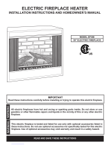
Ref. BREF30/BREF30NH BREF36/BREF36NH/BREF36R BREF42/BREF42NH/BREF42R
A 34” (864 mm) 40" (1016mm) 45
⁵⁷⁄₆₄" (1166mm)
B 36” (914 mm) 36" (914mm) 36" (914mm)
C 30” (762 mm) 36" (914mm) 42" (1067mm)
D 21” (533 mm) 21" (533mm) 21" (533mm)
E 7
¹⁄₂” (191 mm) 7¹⁄₂" (191mm) 7¹⁄₂" (191mm)
F 19
³⁄₄” (502 mm) 19³⁄₄" (502mm) 19³⁄₄" (502mm)
G 14” (356 mm) 14" (356mm) 16" (406mm)
H 27
¹⁄₂” (698 mm) 27¹⁄₂" (698mm) 31¹¹⁄₁₆" (85mm)
Framing Dimensions
J 36¹⁄₂” (927 mm) 36¹⁄₂" (927mm) 36¹⁄₂" (927mm)
K 35” (889 mm) 41" (1041mm) 46
⁵⁷⁄₆₄" (1191mm)
L 14” (356 mm) 14" (356mm) 16" (406mm)
M 37
¹⁄₂” (953 mm) 37¹⁄₂" (953mm) 49" (1245mm)
N 54” (1372 mm) 54" 1372mm) 69¹⁄₂" (1765mm)
O 27” (686 mm) 27" (686mm) 35
¹⁄₄" (895mm)
N
5/8" (16mm)
Recessed
Nailing Flange
G
H
Rough
Opening
Depth
L
Rough
Opening
Height
A
M
M
O
K Rough Opening Width
1/2" (13mm)
5/8" (16mm)
B
J
2¹¹⁄₃₂"
(60mm)
3³⁄₄"
(95mm)
7²⁹⁄₃₂"
(192mm)
E
F
D
E
C
4758
BREF specs
1/04
Voltage: 120 Volt 120 Volt (NH) 240 Volt
Total Amps: 13 Amps 2 Amps 12.9 Amps
Total Watts: 1550 Watts 240 Watts 3100 Watts
Heater Rating: 1455 Watts N/A 2855 Watts
Electrical Specifications
Fireplace Dimensions
Fig. 1 Fireplace specifications and framing dimensions.

10004758
BREF Electric Fireplace
5
J
F
G
H
I
CFM164a
Mantel Leg Chart
06/22/01 sta
Mantels
The height that a combustible mantel is fitted above the
fireplace is dependent on the depth of the mantel. This
also applies to the distance between the mantel leg (if
fitted) and the fireplace.
For correct mounting height and width, refer to Figure
2a and 2b.
The distances and reference points are not affected by
the fitting of a bay window front trim kit.
Noncombustible mantels and legs may be installed at
any height and width around the appliance.
When using paint or lacquer to finish the mantel, such
paint or lacquer must be heat-resistant to prevent dis-
coloration.
Black
Surround
Face
CFM164a
CFM170
DV Builder Front
View
O
N
M
L
K
Side of Combustion
Chamber
CFM170
Fig. 2b Combustible mantel leg minimum installation.
Mantel Mantel Leg from Side
Ref.
Leg Depth
Ref.
of Comb. Opening
F 14" (356 mm) K 14" (356 mm)
G 12" (305 mm) L 12" (305 mm)
H 10" (254 mm) M 10" (254 mm)
I 8" (203 mm) N 8" (203 mm)
J 1
¹⁄₂" (38 mm) O 1¹⁄₂" (38 mm)
Framing
1. Choose fireplace location.
2. Place fireplace into position.
3. Frame in the fireplace with a header across the top.
It is important to allow for finished face when setting
the depth of the frame.
Four (4) nailing flanges are supplied with the fireplace
(found on the fireplace hearth). To level the box and
secure it firmly in place, remove the nailing flanges from
the hearth and install at the sides of the fireplace as
shown in Figure 3.
Mantel Shelf Mantel from Top
Ref.
Depth
Ref.
of Comb. Chamber
V 14" (356 mm) A 25" (635 mm)
W 12" (305 mm) B 23" (584 mm)
X 10" (254 mm) C 21" (533 mm)
Y 8" (203 mm) D 19" (483 mm)
Z 1
¹⁄₂" (38 mm) E 15" (381 mm)
A B C
D
E
V
W
X
Y
Z
CFM146c
Electric Mantel
Chart
1/22/04 djt
Wall
Top of Combustion
Chamber
CFM146b
Fig. 2a Combustible mantel minimum installation.
Mantel Clearances
Mantel Leg

10004758
BREF Electric Fireplace
6
Finishing
CAUTION: All joints between the finished
wall and the appliance surround (top and
sides) may be sealed only with noncom-
bustible material. Only noncombustible
material can be applied as facing to
the appliance surround (the black painted
face).
When finishing the appliance, never obstruct or
modify the air inlet/outlet grilles in any manner.
NOTE: Finish the wall with the material of your
choice. Refer to Figures 2a and 2b for specific
clearances when installing a combustible mantel or
other combustible projection.
Locating your Electric Fireplace
Your new fireplace may be installed into an existing
masonry or zero-clearance fireplace. It may also be in
-
stalled using a prefabricated cabinet available from your
dealer, or be built into a wall.
When choosing a location for your new fireplace, en
-
sure that the general instructions are followed. Also, for
best effect, install the fireplace out of direct sunlight.
Clearance to Combustibles
Sides ......................................................... 0" (0 mm)
Floor .......................................................... 0" (0 mm)
Top ........................................................... 0" (0 mm)
FP549
9/29/97
BR/BC
Nail
side-nailing
flange
Fig. 3 Adjustable drywall strip (nailing flange).
FP549
Hearth
A hearth is not mandatory; however, for aesthetic pur-
poses, we recommend use of a noncombustible hearth
that does not obstruct the air openings.
Cold Climate Installation: To conform to
applicable insulation codes, it is manda-
tory the outer walls be insulated when
installing this unit against a non-insulated
exterior wall or chase.
Cabinet Installations
Cabinets are available from your dealer which allow
fast, convenient installation of your fireplace against
existing walls.
Main Power Wall Switch Wiring
To reduce the risk of fire, electrical shock,
and personal injury, before attempting
maintenance or service, disconnect all
power to the fireplace
at the main service panel.
120 Volt Wall Switch Wiring Installation
A qualified electrician must perform any
electrical wiring of this appliance. For Ca-
nadian installations, wiring must be done
in accordance with local codes, and/or
the current CSA C22.1 Canadian Electrical
Code. For U.S.A. installations, wiring must
be done in accordance with the National
Electrical Code ANSI/ NFPA No. 70.
NOTE: For 120 Volt installations, use a
single-pole, single-throw, 20 Amp-rated wall switch.
(NH models do not require the 20 Amp switch. A
regular 15 Amp wall switch may be used.)
Wiring of the wall switch must be completed prior
to installing the unit.
Connect the wall-mounted switch to the fireplace by
running grounded 2-conductor wire (Min. 14 AWG) to
the switch from the junction box on the side of the unit.
1. Locate the voltage selection switch under the logset
on the left front corner of the unit. (Not applicable to
NH models)
2. Ensure the switch is in the 120 Volt position. (Not
applicable to NH models.)
3. Loosen the screws securing the junction box cover,
and remove the cover.
4. Remove knockouts in the box cover to use a cable
clamp.
5. Pull out two (2) wires: black and white.
6. Connect the hot wire (black) from the wall switch to
the L1 (black) wire on the unit, and the other wire
from the wall switch to the L1 (black) wire on the
power supply.

10004758
BREF Electric Fireplace
7
240 Volt Wall Switch Wiring Installation
A qualified electrician must perform any
electrical wiring of this appliance. For
Canadian installation, wiring must be done
in accordance with local codes, and/or
the current CSA C22.1 Canadian Electrical
Code. For U.S.A. installation, wiring must
be done in accordance with the National
Electrical Code ANSI/NFPA No. 70.
NOTE: For 240 Volt installations, use a double-pole,
single-throw, 20 Amp, 240V rated wall switch.
Wiring of the wall switch must be completed prior
to installing the unit.
Connect the wall-mounted switch to the fireplace by
running grounded 3-conductor wire (MIN. 14 AWG) to
the switch from the junction box on the side of the unit.
1. Locate the voltage selection switch under the logset
on the left front corner of the unit.
2. Move the switch from the 120 Volt to the 240 Volt
position.
3. Loosen the screws securing the junction box cover,
and remove the cover.
4. Remove knockouts in the box cover to use a cable
clamp.
5. Pull out three (3) wires: black, red, and white.
6. Connect one (1) wire (black) from the wall switch to
the L1 (black) wire on the unit, and the other wire
from the wall switch to the L1 (black) wire on the
power supply.
7. Connect one (1) of the wires from the wall switch to
the L2 (red) wire on the unit, and the other wire from
the wall switch to the L2 (red) wire on the power sup-
ply.
8. Connect the white wire from the unit to the neutral
(white) wire on the power supply.
9. Connect the ground wire from the wall switch to the
wire grouping from the power supply and ground
stud in the junction box.
10. Ensure all connections are tight. Insert all wiring
inside the junction box and secure the cover.
7. Connect the white wire from the unit to the neutral
(white) wire on the power supply.
8. Connect the ground wire from the wall switch to the
wire grouping from the power supply and the ground
stud in the junction box.
9. Make sure the red wire (L2) in the junction box has a
closed end splice or a wire nut properly applied.
10.Ensure all connections are tight. Insert all wiring
inside the junction box and secure the cover.
120/240 Volt Wall-Mounted
Thermostat Wiring
Before attempting maintenance or ser-
vice—to reduce risk of fire, electrical
shock and personal injury—disconnect all
power to the fireplace at the main service
panel.
NOTE: Wiring of the wall thermostat must be com
-
pleted prior to the installation of the unit.
Use a single pole thermostat rated for 120/240 Volt
operation.
When installing the wall thermostat, make sure to
turn the heater control inside fireplace all the way
clockwise to the highest set point temperature.
Connect the wall-mounted thermostat to the fireplace
by running a grounded 2-conductor wire (min. 14 AWG)
to the thermostat from the junction box on the side of
the unit.
1. Loosen the screws securing the junction box cover
and remove the cover.
2. Remove knockouts in the box cover to use a cable
clamp.
3. Pull out the two (2) brown wires with the closed end
splice at the end.
4. Cut off the closed end splice, separate the two wires,
and strip approximately 5/8" (15mm).
5. Connect one (1) wire from the thermostat to one (1)
of the brown wires; connect the other wire from the
thermostat to the other brown wire.
6. Connect the ground wire from the wall thermostat to
the power supply wire group and the ground stud in
the junction box.
7. Ensure all connections are tight. Insert all wiring into
the junction box and secure the cover.
Installation Cautions
Make sure the power is turned OFF before
proceeding.
If repairing or replacing any electrical com-
ponent or wiring, the original wire routing,
color coding and securing locations must
be followed.
Any electrical repairs or rewiring of this
unit should be carried out by a licensed
electrician in accordance with national and
local codes.

10004758
BREF Electric Fireplace
8
120 Volt Unit Installation
1. Locate the switch under the logset on the left front
corner of the unit.
2. Check the voltage selection switch position to ensure
it is in the 120 Volt position.
3. Loosen the screws securing the junction box cover
and remove the cover.
4. Remove knockouts in the box cover to use the cable
clamp.
5. Pull out two (2) wires: black and white.
6. Connect the black wire from the unit to the L1 (black)
from the power supply. Connect the white wire from
the unit to the neutral (white) from the power supply.
NOTE: Wiring must be connected to a 20 Amp
dedicated circuit breaker or fuse in the electrical
panel of the dwelling.
7. Connect the ground wire from the power supply to
ground stud in the junction box.
8. Make sure the red wire (L2) in the junction box has a
closed end splice or a wire nut properly applied.
9. When the unit has been configured for the appropri-
ate power supply voltage, ensure all connections
are tight. Insert all wiring inside the junction box and
secure the cover.
10. Turn the power to the unit on at the breaker/fuse
panel. Place the unit into operation and check to
make sure the whole system is operating properly.
120 Volt (NH) Unit Installation
1. Loosen the screws securing the junction box cover
and remove the cover.
2. Remove knockouts in the box cover to use the cable
clamp.
3. Pull out two (2) wires: black and white.
4. Connect the black wire from the unit to the L1 (black)
from the power supply. Connect the white wire form
the unit to the neutral (white) form the power supply.
5. Connect the ground wire from the power supply to
the ground stud in the junction box.
6. Ensure all connections are tight. Insert all wiring
inside the junction box and secure the cover.
7. Turn the power to the unit on at the breaker/fuse
panel. Place the unit into operation and check to
make sure the system is operating properly.
240 Volt Unit Installation
1. Locate the voltage selection switch under the logset
on the left front corner of the unit.
2. Check the switch position to ensure it is in the
240 Volt position.
3. Loosen the screws securing the junction box cover
and remove the cover.
4. Remove knockouts in the box cover to use the cable
clamp.
Resetting the
Temperature Cutout Switch
To reduce the risk of fire, electrical shock,
and personal injury, before attempting
maintenance or service, disconnect all
power to the fireplace at the main service
panel.
NOTE: The heater on this fireplace is protected with
a safety limit device to prevent overheating. Should
the heater overheat, an automatic cutout turns the
heater OFF; it will not come back ON without being
manually reset.
The safety limit device is located in a cutout at the right
front top corner by the cover fan/ heater. To reset the
switch, insert a small flat screwdriver into this cutout
and push the reset button on the safety limit device.
5. Pull out three (3) wires: black, red, and white.
6. The unit is shipped from factory with a closed end
splice on the red wire. Cut off this splice and strip
approximately 5/8" (15mm) wire sheathing.
7. Connect the black wire from the unit to the L1
(black) from the power supply. Connect the red wire
from the unit to the L2 (red) from the power supply.
Connect the white wire from the unit to the neutral
(white) from the power supply.
NOTE: Wiring must be connected to a 20 Amp
dedicated circuit breaker or fuse in the electrical
panel of the dwelling.
8. Connect the ground wire from the power supply to
ground stud in the junction box.
9. When the unit has been configured for the appropri-
ate power supply voltage, ensure all connections
are tight. Insert all wiring inside the junction box and
secure the cover.
10. Turn the power to the unit on at the breaker/fuse
panel. Place the unit into operation and check to
make sure the whole system is operating properly.
FP1452
Safety limit switch
2/25/04 djt
Safety Limit Device
Small Flat Screwdriver
Cover Fan/
Heater
FP1452
Fig. 4 Reset the switch with a small flat screwdriver.

10004758
BREF Electric Fireplace
9
Screen Kit Installation
1. Remove the plastic bag from each screen.
2. Remove the four (4) metal clips, two (2) for each
side of the fireplace opening.
3. Slide screen panels against sides of the fireplace
opening.
4. Align each metal clip with the hole it was removed
from, while at the same time, hooking the clip
through the last wire of the screen. Snap clips into
place. (Fig. 5)
5. Pull screens back and forth to ensure they work
freely.
Fp1041
screen install
3/30/00 djt
(Clip)
Fig. 5 Clip installation.
FP1041
Service Instructions
To reduce the risk of fire, electrical shock
or personal injury, disconnect all power
coming to the fireplace at the main service
panel before attempting any maintenance
or cleaning.
Maintenance of Motor
The motors used on the fan and the drum assemblies
are pre-lubricated for extended bearing life, and require
no further lubrication. However, periodic cleaning/vacu-
uming of the fan/ heater is recommended.
Installation of BREF36/BREF36R
with Ceramic Log Set
1. Turn OFF power to the unit at the main service
panel.
2. Open glass (if applicable); open the steel curtain.
3. Remove logs from packaging.
NOTE: The ember lava rock is shipped in place;
no adjustment is necessary.
4. Fit the right log (B111) onto the plate log support.
Ensure the bottom holes of B111 are located on the
two pins of the support.
5. Place the center log (B112) on the ember lava rock.
Use the notches under the center portion of B112 to
locate it properly.
6. Place the bottom left log (B113) into position by rest-
ing the hole under the center of B113 over the knob
on center top of B112. The other end of B113 rests
against the back wall of the plate log support.
7. Fit the top left log (B114) onto the plate log support.
Ensure the bottom holes of B114 are located on
the two (2) pins of the support; rest the other end of
B114 on the top back of B113.
LG241
DEF36 logs
6/02
B114
B111
B113
B112
LG241
Fig. 6 BREF/BREF36R ceramic log set placement.
Installation of BREF42/BREF42R
with Ceramic Log Set
1. Turn OFF power to the unit at the main service
panel.
2. Open glass (if applicable); open the steel curtain.
3. Remove logs from packaging.
NOTE: The ember lava rock is shipped in place;
no adjustment is necessary.
4. Place the front center log (G3) on the ember lava
rock. Use the notches under the center front of the
log to properly locate the log.
5. Fit the right rear log (G1) on the place support. En
-
sure the bottom holes of G1 are located on the two
(2) pins of the support; rest the other end of G1 on
the top back of G3.
6. Fit the left rear log (G2) on the place support. Ensure
the bottom holes of G2 are located on the two (2)
pins of the support.
7. Place the front left log (G4) in position by resting the
front left back log on the top right log rear left (G2).
The front of this log will rest against the back wall of
the log support plate.

10004758
BREF Electric Fireplace
10
8. Place the right front log (G5) in position on the
ember lava rock. Use the notches under the log front
right to have a proper location.
LG324
BREF42 logs
1/04
G2
G1
G4
G3
G5
LG324
Fig. 7 BREF42/BREF42R ceramic log placement.
To reduce the risk of fire, electrical shock
or personal injury, disconnect all power
coming to the fireplace at the main service
panel before attempting any maintenance
or cleaning.
Replacing Light Bulbs
This fireplace uses four (4) clear, 120 Volt, 60 Watt,
E-12 socket base (small base, chandelier candle-type)
light bulbs. These lights are located under the ember
bed of the unit.
Do not exceed 60 Watts per bulb. Use of
higher-rated bulbs may result in fire, caus-
ing property damage, personal injury, or
loss of life.
NOTE: For the sake of convenience, you may wish
to consider replacing all the light bulbs if one of
them burns out.
1. Turn OFF the power to the unit at the main service
panel.
2. If the fireplace has been operating, allow it to cool.
3. Open glass (if applicable); open steel curtain.
4. Remove the log. Remove the two (2) screws, one
on each side of the ember bed/plate support log set
down. Remove the ember bed/plate support log set.
5. Examine the bulbs to determine which one(s) need
to be replaced (if you are not going to replace all).
7. Install new light bulb(s) by screwing in while holding
the socket.
8. Reinstall the ember bed, log set, glass door, and
steel curtain.
Cleaning Trim
Clean the trim using a soft cloth you have slightly damp-
ened with lemon oil; then buff with a clean soft cloth.
NOTE: You can obtain lemon oil at super-markets
and hardware stores. Do not use commercially
made brass polish or household cleaners, as these
products will damage the trim.

10004758
BREF Electric Fireplace
11
Component Identification
1. Heater Element 8. Flame Motor
2. Limit Control, 175/20 DIF 9. Light Bulb
3. Relay Switch, 120V 50/60Hz 10. Light Socket w/Wiring Assembly
4. Fan/Heater Motor 11. Cable Tie, Nylon 6" - 1¹⁄₂" Black
5. Thermostat 12. Bushing Snap, Split 1"
6. Switch, Rocker 13. Closed End Splice, 2/18 Ga.Wire
7. Switch 14. CFM Wire
15. Sensor, 230°F, Manual Reset
FRONT
REAR
13
13 BLACK
2
14 BLACK
COIL
6
5
4
3
2
8
3
15
3 BLACK
4 BLACK
21 WHITE
18 WHITE
19 WHITE
20 WHITE
17 WHITE
WHITE
2 WHITE
7 BLACK
12 BROWN
8 BLACK
14 BLACK
11 RED
5 RED
1
5
4
6
12
7
10
11
9
6 BLACK
15 WHITE
BLACK
BLACK
1 WHITE
G
16 WHITE
WHITE
T'S
10 BLACK
22 WHITE
9 RED
N
L1
MOTOR
FLAME
MOTOR
FAN/HEATER
12 BROWN
L2
13
FP1449
BREF wiring
2b
2
2a
1b
1
1a
Electrical Wiring Diagram without Integral Remote Control
For Units with Ceramic Log Sets (Refer to Figures 6 & 7)
FP1449
Fig. 8 Wiring Diagram for units with ceramic log set. (Refer to Figure 6 & 7)

10004758
BREF Electric Fireplace
12
FAN/HEATER
MOTOR
FLAME
MOTOR
L2
L1
N
11 RED
22 WHITE
12 BLACK
T'S
WHITE
18 WHITE
G
1 WHITE
BLACK
BLACK
17 WHITE
7 BLACK
6 RED
13 RED
16 BLACK
9 BLACK
14 BROWN
8 BLACK
2 WHITE
WHITE
23 WHITE
19 WHITE
24 WHITE
21 WHITE
4 BLACK
5 BLACK
1
2
3
4
5
6
COIL
16 BLACK
15 BLACK
REAR
FRONT
14 BROWN
1a
1
1b
2a
2
2b
25 RED
IN INOUT OUT
LNN L
12
13
13
5
4
2
3
15
1
9
11
10
16
7
8
20 WHITE
10 BLACK
3 BLACK
4 BLACK
FP1450
BREF wiring diagram
w/remote
6
Electrical Wiring Diagram with Integral Remote Control
For Units with Ceramic Log Sets (Refer to Figures 6 & 7)
Component Identification
1. Heater Element 9. Light Bulb
2. Limit Control, 175/20 DIF 10. Light Socket w/Wiring Assembly
3. Relay Switch, 120V, 50/60Hz 11. Cable Tie Nylon 6"-1
¹⁄₂" Black
4. Fan/Heater Motor 12. Bushing Snap, Split 1"
5. Thermostat 13. Closed End Splice 2/18 Ga.Wire
6. Switch, Rocker 14. CFM Wire
7. Switch 15. Sensor, 230°F Manual Reset
8. Flame Motor 16. Receiver
FP1450
Fig. 9 Wiring Diagram for units with ceramic log set. (Refer to Figures 6 & 7) BREF36R/BREF42R

10004758
BREF Electric Fireplace
13
FAN/HEATER
MOTOR
FLAME
MOTOR
L2
L1
N
11 RED
22 WHITE
12 BLACK
T'S
WHITE
18 WHITE
G
1 WHITE
BLACK
BLACK
17 WHITE
7 BLACK
6 RED
13 RED
16 BLACK
9 BLACK
14 BROWN
8 BLACK
2 WHITE
WHITE
23 WHITE
19 WHITE
24 WHITE
21 WHITE
4 BLACK
5 BLACK
1
2
3
4
5
6
COIL
16 BLACK
15 BLACK
REAR
FRONT
14 BROWN
1a
1
1b
2a
2
2b
25 RED
IN
IN
OUT
OUT
L
N
N
L
12
13
16
5
4
2
3
15
1
9
10
17
7
3
20 WHITE
10 BLACK
3 BLACK
4 BLACK
BLACK
BLACK
RED
WHITE
FP1541
BREF
heat wiring
1/05
Component Identification
1. Heater Element 9. Light Bulb
2. Limit Control, 175/20 DIF 10. Light Socket w/Wiring Assembly
3. Relay Switching, 120V, 50/60Hz 12. Bushing Snap, Split 1"
4. Fan/Heater Motor 13. Closed End Splice 2/18 Ga. Wire
5. Thermostat 14. CFM Wire Req'd BREF36
6. Switch, Rocker 15. Sensor, 230°F Manual Reset
7. Switch 16. Closed End Splice 3/4" 18GA Wire
8. Flame Motor 17. Receiver
Electrical Wiring Diagram with Heater and Integral Remote Control
FP1541
Fig. 10 Wiring diagram for models with heat.

10004758
BREF Electric Fireplace
14
CFM Component Identification
1. Switch
2. Flame Motor
3. Light Bulb
4. Light Socket w/Wiring Assembly
6. CFM Wire req'd
Electrical Wiring Diagram without Heater and Integral Remote Control
FP1540
Fig. 14 Wiring diagram for models without heat. (BREF30NH/BREF36NH/BREF42NH)
5 WHITE
2 BLACK
L1
N
G
3 BLACK
6 WHITE
1 BLACK
7 WHITE
4 BLACK
BLACK
WHITE
BLACK
WHITE
MOTOR
FLAME
3
4
2
1
8 WHITE
I
O
3
2
1
FP1540
BREF
no heat wiring
1/05

10004758
BREF Electric Fireplace
15
Operating Instructions
For units with ceramic log sets. (Figs. 6 & 7)
This set of instructions applies to units with ceramic log
sets. (Figs. 6 & 7) The control compartment is located
inside the fireplace behind the steel curtain near the
left front corner. To access the controls, simply slide the
steel curtain open.
FP1451a
control panel
units w/ceramic logs
5/05
1. ON/OFF Switch
3. Learn
2. Heater Control
4. ON/OFF
FP1451a
Control Panel
Fig. 12 Control panel.
1. ON/OFF Switch
The ON/OFF switch is for supplying power to light ef-
fects of the fireplace. This switch is normally illuminated
to indicate there is electrical power to the unit.
2. Heater Control
The heater control acts to turn the heater ON and OFF,
as well as setting the comfort level in the room.
Turn the knob clockwise form the "OFF" position to
place the heater into operation. The further the knob is
rotated clockwise, the higher the set point temperature.
Turn the knob counterclockwise to lower the set point
temperature. Turn it all the way counterclockwise to turn
the heater function OFF.
3. Relearn
The BREF36R and BREF42R fireplaces with integral
remote control have pre-programmed, matched-pair
receiver/transmitters already set with randomly selected
house codes. It is highly unlikely that the fireplace code
will ever need to be relearned. If the fireplace needs to
relearn receiver/transmitter house codes, perform the
following steps:
1. Be sure there is power to the fireplace.
2. Be sure there is a good battery in the transmitter
(hand-held remote).
3. Open the battery compartment of the remote.
4. Press and release the small button located in the top
left corner. This will randomly select a new house
code in the remote transmitter.
5. Close the remote transmitter battery compartment.
6. Press either the ON or OFF button on the remote
transmitter, and the Learn button on the fireplace at
the same time. The fireplace is now ready to accept
commands from the remote transmitter.
4. ON/OFF
The ON/OFF button on the fireplace (below the Learn
button) is to turn the fireplace ON and OFF when the
battery in remote transmitter is weak, or to manually
operate the fireplace without the remote transmitter.
NOTE: The device complies with Part 15 of the FCC
Rules. Operation is subject to the following two
condition:
1. This device may not cause harmful interference,
and
2. This device must accept any interference re-
ceived, including interferences that may cause
undesired operation.

10004758
BREF Electric Fireplace
16
Operating Instructions
For all other units.
The control compartment is located inside the fireplace
behind the steel curtain near the left front corner. To ac
-
cess the controls, simply slide the steel curtain open.
NOTE: The device complies with Part 15 of the FCC
Rules. Operation is subject to the following two
conditions:
1. This device may not cause harmful interference,
and
2. This device must accept any interference re
-
ceived, including interference that may cause
undesired operation.
FP1451
control panel
1/04
Control Panel
1. ON/OFF Switch
2. Heater Control
FP1451
Fig. 13 Control panel.
1. ON/OFF Switch
The ON/OFF switch is for supplying power to light ef-
fects of the fireplace. This switch is normally illuminated
to indicate that there is electrical power to the unit.
2. Heater Control
The heater control acts to turn the heater ON and OFF,
as well as setting the comfort level in the room.
Turn the knob clockwise from the "OFF" position to
place the heater into operation. The further the knob is
rotated clockwise, the higher the set point temperature.
Turn the knob counterclockwise to lower the set point
temperature. Turn it all the way counterclockwise to turn
the heater function OFF.
3. Remote Control
If the unit is equipped with an on/off remote control, this
feature is to turn the flame effect on and off remotely
while the switch on the control panel is off. If the control
panel switch is on, this bypasses the remote control.
The receiver and transmitter is a matched-pair that
is pre-programmed and must be replaced together, if
necessary.

10004758
BREF Electric Fireplace
17
BREF36/BREF36R
1a
1b
1c
1d
5
4
3
6
7
2
8
12
13
15
16
17
4758
BREF older parts
5/05
14
10
18
BREF42/BREF42R
CFM Specialty Home Products reserves the right to make changes in design, materials, specifications, prices and discontinue colors and products
at any time, without notice.
BREF36/42, BREF36R/42R Electric Fireplace
for Units with Ceramic Log Sets

10004758
BREF Electric Fireplace
18
BREF36/42, BREF36R/42R Electric Fireplace
for Units with Ceramic Log Sets (continued)
Ref. Description BREF36 BREF36R BREF42 BREF42R
1. Log Set Complete 10004797 10004797 10004950 10004950
1a. Log 10004470 (B111) 10004470 (B111) 10004945 (G1) 10004945 (G1)
1b. Log 10004471 (B112) 10004471 (B112) 10004946 (G2) 10004946 (G2)
1c. Log 10004472 (B113) 10004472 (B113) 10004947 (G3) 10004947 (G3)
1d. Log 10004473 (B114) 10004473 (B114) 10004948 (G4) 10004948 (G4)
1e. Log -- -- 10004949 (G5) 10004949 (G5)
2. Heater Element 10004584 10004584 10004584 10004584
3. Motor, AC, w/Terminals 10004262 10004262 10004262 10004262
4. Rocker Switch (Illuminated) 10001393 10001393 10001393 10001393
5. Thermostat - Heater Control 10002987 10002987 10002987 10002987
6. Fan w/Bracket Assembly 10004695 10004695 10004695 10004695
7. Sensor, 230°F Manual Reset 10004720 10004720 10004720 10004720
8. Knob - Flame Speed, Heater Controls 10001639 10001639 10001639 10001639
9. Light Filter - Ember Bed (Not shown) 10004518 10004518 10004957 10004957
10. Plate Control Assembly 10006386 10006389 10006386 10006389
11. Screen Tinted Plastic (Not shown) 10006381 10006381 10006391 10006391
12. Ember Lava Rock 10004517 10004517 10004958 10004958
13. Flame Generator Assembly 10003350 10003350 10004847 10004847
14. Plate Log Support Assembly 10006380 10006380 10004853 10004853
15. Socket Light Bulb Lower Assembly 10003568 10003568 10003568 10003568
16. Limit Control, 175/20 DIF 10001172 10001172 10001172 10001172
17. Transmitter -- 10005140 -- 10005140
18. Receiver -- 10005141 -- 10005141
19. CFM Wire Req'd (Not shown) 10004851 10006382 10004851 10006382

10004758
BREF Electric Fireplace
19
CFM Specialty Home Products reserves the right to make changes in design, materials, specifications, prices and discontinue colors and products
at any time, without notice.
BREF30/36/42, BREF30NH/36NH/42NH Electric Fireplace
BREF30/36, BREF30/36NH
BREF42/BREF42NH
5
4
3
6
7
2
8
9
11
12
13
15
16
17
4758
BREF parts
1/05
14
20
23
21
22
21
1
1

10004758
BREF Electric Fireplace
20
Accessory Description Model Number
Thermostat Wall Thermostat, electric fireplace EBWT
Power Cord 10003095
Refractory Kit Refractory panels give the appliance BREF30RK
(not available for a realistic brick look BREF36RK
units with ceramic BREF42RK
log set)
Bi-fold Glass Doors Glass doors enhance the viewing area Brushed Brass - 30GDKBB, 36GDKBB, 42GDKBB
of the fireplace Black - 30GDKBK, 36GDKBK, 42GDKBK
Polished Brass - 30GDKDP, 36GDKDP, 42GDKDP
Pewter - 30GDKS, 36GDKS, 42GDKS
Accessories
The following accessories for these appliances are
available from your local CFM Specialty Home Products
distributor.
NOTE: Each accessory comes with a separate in
-
stallation instruction for mounting to the particular
appliance. Be sure to read each instruction thor-
oughly before installing.
See your CFM Specialty Home Products distributor or
dealer for other finishing options, such as marble and
mantels that are available in a wide selection of styles.
BREF30/36/42, BREF30NH/36NH/42NH Electric Fireplace
(continued)
Ref. Description BREF30 BREF30NH BREF36 BREF36NH BREF42 BREF42NH
1. Log Set Complete 10006532 10006532 10006532 10006532 10007664 10007664
2. Heater Element 10004584 -- 10004584 -- 10004584 --
3. Motor, AC, w/Terminals 10004262 10004262 10004262 10004262 10004262 10004262
4. Rocker Switch (Illuminated) 10001393 10001393 10001393 10001393 10001393 10001393
5. Thermostat - Heater Control 10002987 -- 10002987 -- 10002987 --
6. Fan w/Bracket Assembly 10004695 -- 10004695 -- 10004695 --
7. Sensor, 230°F Manual Reset 10004720 -- 10004720 -- 10004720 --
8. Knob - Heater Controls 10001639 -- 10001639 -- 10001639 --
9. Plate Control Assembly 10007610 10007830 10007443 10007608 10007443 10007608
10. Screen Tinted Plastic (Not Shown) 10007612 10007612 10007430 10007430 10006391 10006391
11. Ember Lava Rock 10007461 10007461 10007461 10007461 10007667 10007667
12. Flame Generator Assembly 10003350 10003350 10003350 10003350 10004847 10004847
13. Support Plate 10007434 10007434 10007434 10007434 10007673 10007673
14. Plate Log Support Assembly 10007447 10007447 10007447 10007447 10007666 10007666
15. Socket Light Bulb Lower Assembly 10006453 10006453 10006453 10006453 10006453 10006453
16. Limit Control, 175/20 DIF 10001172 -- 10001172 -- 10001172 --
17. Transmitter 10008487 -- 10008487 -- 10008487 --
18. Receiver 10008487 -- 10008487 -- 10008487 --
19. CFM Wire Req'd (not shown) 10006382 10007639 10006382 10007639 10006382 10007639
20. Screen Assembly 7554299 7554299 7554338 7554338 7554340 7554340
21. Screen Rod 3993138 3993138 10007433 10007433 10007433 10007433
22. One Piece Screen Pull (2 per Fireplace) 7554239 7554239 7554239 7554239 7554239 7554239
23. Cable Clip (4 per Fireplace) 7512135 7512135 7512135 7512135 7512135 7512135
NOTE: Items 17 and 18 (Transmitter and Receiver) must be replaced as a set.
/