Page is loading ...

C US
®
READ AND SAVE THESE INSTRUCTIONS
ELECTRIC FIREPLACE HEATER
INSTALLATION INSTRUCTIONS AND HOMEOWNER’S MANUAL
MODEL EF500
39" ELECTRIC FIREPLACE
IMPORTANT
Read these instructions carefully before installing or trying to operate this electric replace.
WARNING
All electric replaces have hot and arcing or sparking parts inside. Do not store or use
gasoline or other ammable vapors and liquids in the vicinity of this or any other electric
replace.
WARNING
This electric replace is tested and listed for use only with optional accessories listed in
these instructions. Do not use optional accessories not specically tested for this electric
replace. Use of optional accessories may void warranty and result in a safety hazard.

2 68D0018
CONTENTS
INSTALLER
Please leave these instructions with the owner.
OWNER
Please retain these instructions for future reference
.
IMPORTANT
Read these instructions carefully before installing or trying to operate this electric replace.
Important Safety Information .......................... 2
Listing Approvals ............................................ 3
Product Specications..................................... 4
Pre-Installation Information ............................. 4
Locating Electric replace ............................. 5
Unpacking and Testing Electric replace ...... 6
Framing Electric replace.............................. 6
Framing Dimensions .................................... 7
Electrical Connections .................................. 8
Electric replace Installation ........................ 10
Operating Instructions ...................................11
Control Panel Operation ..............................11
Remote Control —Hand Held Transmitter
Operation .................................................... 12
Cleaning and Maintenance ........................... 13
Cleaning Electric replace Compartment ... 13
Cleaning Back Glass .................................. 14
Bulb Replacement ...................................... 14
Blower and Electric replace Replacement 15
Troubleshooting ............................................ 16
Replacement Parts ......................................... 17
Warranty ...........................................Back Cover
IMPORTANT SAFETY INFORMATION
WARNING
Improper installation or
use of the electric replace
can cause serious injury or
property damage. Use this
manual for reference. For
assistance or additional
information, consult a
qualied installer.
CAUTION
Do not expose electric
replace to elements such
as rain, etc.
WARNINGS
• Due to high temperatures, the electric replace should
be located out of trafc and away from furniture and
draperies.
• Never place any object on the electric replace.
• Never place clothing or other ammable material on
or near the electric replace.
• Electric replace becomes very hot when running.
Keep children and adults away from the hot surface of
electric replace to avoid burns or clothing ignition.
• Electric fireplace will remain hot for a time after
shutdown. Do not touch electric replace before it
cools.
• Carefully supervise young children when they are in
the room with the electric replace.
Take the following basic precautions when using electri-
cal replaces to reduces the risk of re, electric shock
and personal injury.
DANGER
Never locate electric replace where it could
fall into a bathtub or other water container.

68D0018 3
IMPORTANT SAFETY INFORMATION
IMPORTANT SAFETY INFORMATION (continued)
6. Do not use electric replace in bathrooms, laundry areas,
or similar indoor locations.
7. Do not run power cord under carpeting or cover power
cord with throw rugs. Make sure power cord is away from
trafc area where it will not be tripped over.
8. Turn electric replace controls to “OFF” before removing
the plug from the outlet.
9. Use this electric replace only as described in this manual.
Using electric replace in any way not recommended
by the manufacturer may cause re, electric shock or
personal injury.
10. Do not use an extension cord with electric replace. An
extension cord may overheat and cause a re. If you must
use an extension cord, use a No. 14 AWG minimum size
cord that is rated not less than 1875 WATTS.
11. Always use properly grounded fused and polarized out-
lets.
12. Always use ground fault protection where required by
electrical codes.
13. Always unplug electric replace before performing any
cleaning or maintenance.
14. Always unplug electric replace before moving it.
15. Always use a certied electrician to install new circuits
or outlets.
16. Always keep electric replace free from excessive vibra-
tion when transporting electric replace.
17. Keep electric replace dry when transporting electric
replace.
18. Always store electric replace in dry place.
This electric replace has been tested in accordance with UL 2021 and CSA C22.2 No. 46 standards for a xed location
dedicated electric room heaters.
Installation must conform to local codes. In absence of local codes, electrical wiring must comply with the latest edition of
the National Electrical Code ANSI/NFPA 70 in the USA. In Canada, comply with latest edition of the current CSA C22-1
Canadian Electrical Code.
LISTING APPROVALS
1. Keep combustible materials such as furniture, pillows,
bedding, papers, clothing, and curtains at least 3' from
front of electric replace. Also keep combustible materials
away from the sides and back of electric replace.
2. Always unplug electric replace when not in use.
3. Do not operate electric replace with a damaged cord or
plug.
4. Do not operate electric replace if electric replace mal-
functions or has been dropped or damaged in any way.
5. Do not use electric replace outdoors.
WARNING
Do not insert or allow foreign objects
to enter any ventilation or exhaust
opening of electric replace. This may
cause electric shock, re, or damage to
electric replace.
WARNING
RISK OF FIRE!
Do not block air intakes of electric
replace. Blocking air intakes can
cause a re.
WARNING
Do not burn wood or other materials in
this electric replace. This could cause
a re.


68D0018 5
PRE-INSTALLATION INFORMATION
LOCATING ELECTRIC FIREPLACE
Figure 2 illustrates a variety of ways the electric replace may be located in a room. The electric replace may be installed
directly on the oor, carpet or raised on a hearth.
Figure 2 - Electric Fireplace Locations
WARNING
Due to high temperatures, this electric
replace should be located out of trafc.
Keep combustible materials such as
furniture, pillows, bedding, papers,
clothes and curtains at least three (3)
feet (.9m) from the front of the electric
replace.
WARNING
To prevent contact with sagging or
loose insulation, the electric replace
must not be installed against vapor
barrier or exposed insulation. Localized
overheating could occur and a re could
result.
CAUTION
Wear gloves and safety glasses for
protection during installation and
maintenance.
CAUTION
Do not expose the electric replace to the
elements (such as rain, etc.)
CAUTION
Never locate this electric replace where
it may fall into a bathtub or other water
container.
NOTICE
Minimum and maximum clearances must be maintained at all times. Illustrations throughout
these instructions show typical installations and are for design purposes only. Actual
installations may vary slightly due to individual preferences

6 68D0018
FRAMING ELECTRIC FIREPLACE
Electric replace framing can be built before or after the electric replace is set in place. Construct electric replace fram-
ing following Figure 3 and the chart below for your specic installation requirements. See Figure 1 on Page 4 for electric
replace dimensions. The framing headers may rest on the top of the electric replace standoffs.
The electric replace may be installed directly on a combustible oor or raised on a platform of an appropriate height. When
the electric replace is installed directly on carpeting, tile, or other combustible material, other than wood ooring, the electric
replace shall be installed on a metal or wood panel extending the full width and depth of the enclosure.
When framing with combustibe materials,all required clearances to combustibles must be adhered to. Header height is mea-
sured from the base of the electric replace.
Tools and building supplies required for installation:
• Saw • Square
• Framing materials • Pliers
• Caulking Material • Surround
• Tape measure • Gloves
• Phillips Screwdriver • Hammer
• Electric Drill/Bits • Level
• Wall-nishing Materials
UNPACKING AND TESTING ELECTRIC FIREPLACE
Carefully remove the electric replace from the box. Prior to permanently installing the electric replace, test to make sure
the electric replace operates properly.
CAUTION
Do not operate the electric replace if it is damaged
or has malfunctioned. If you suspect the electric
replace is damaged, return the electric replace
to an authorized service facility for examination,
electrical or mechanical adjustment or repair.

68D0018 7
BJ
A
I
H
G
D
F
E
A
C
1/2" or 5/8"
C
A
G
C
G
A1/2" or 5/8"
Nailing
tabs will
accommodate
½" or 5/8"
nished
material
Nailing
tabs will
accommodate
½" or 5/8"
nished
material
Corner Installation
Stud Location
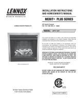
EF500
AFront Wall Opening 393/4"
BFraming Height 331/2"
CBack Width of Electric re- 331/4"
DWidth to Corner 165/8"
ECorner Clearance Width 603/8"
FDepth from Electric replace 301/4"
GElectric replace Framing 155/8"
HCorner Wall Length 423/4"
IElectric replace Opening
Height
211/8"
JElectric replace Opening
Width
36"
Inside Chase Installation
Recessed Installation
FRAMING DIMENSIONS
Figure 4 - Framing Dimensions
WARNING
Do not ll spaces around electric
replace with insulation or other
materials. This could cause a re.

8 68D0018
Junction Box
Control Board
H1+Fan
Motor
H2
P-L
NO
NI
Lamp
Fire
Fuse
SIP2
Heater Heater
Heater Heater
M
F
Temp
Fuse
Temp
Switch
LL
Control Panel
1. IR
2. Flame Switch
3. Heater Switch
4. Set Temp LED (3-Color)
5. Power LED (Green
SIP3
N1
L2
N2
L1
N
G
From Fireplace
Junction Box
N1
L2
N2
L1
N
G
L
N
G
Junction Box
N1
N2
L1
N
G
L1
N
G
L2L2
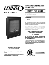
PRE-INSTALLATION INFORMATION
Figure 5 - Wiring Diagram
Figure 6 - Wiring
Connection for 120
Volts, 1500 Watts
Figure 7 - Wiring
Connection for 240
Volts, 3000 Watts
ELECTRICAL CONNECTIONS
Wire a dedicated, properly fused circuit
with a 20 Amp rating for the appropriate
voltage (120V or 240 V). Preferably, the
electric replace will be on a dedicated
circuit, as other electric replaces on
the same circuit may cause the circuit
breaker to trip, or the fuse to blow, when
the electric replace is in operation. See
Figures 5 through 7.
ELECTRICAL SPECIFICATIONS
Power Requirements
Rated Wattage Amperage
120 Volt, 60 Hz. 1500 Watts 13.33 Amps
240 Volt, 60 Hz 3000 Watts 13.33 Amps
WARNING
El e ct r ic a l wi r in g mus t
comply with local building
codes and other applicable
regulations to reduce risk
of re, electrical shock and
injury to individuals.
WARNING
Any electrical rewiring of
this electric replace must
be done by a qualified
electrician.
WARNING
Do not use this electric
fireplace if any part of it
h a s b e e n u n d e r w a t e r.
Immediately call a qualied
service technician to inspect
electric fireplace. Replace
any part of the electrical
system which has been
under water.

68D0018 9
INSTALLATION INSTRUCTIONS
1. Complete the framing opening to the dimensions specied in Figure 4, page 7.
2. Make sure there is a minimum of 8" of service cable for connection to the junction box on the electric replace. Remove
outer jacket and strip the individual wires 1/2" from the end.
3. Loosen the screw securing the junction box cover. Remove the cover.
4. Position electric replace into the framed in opening. Attach electric replace to frame using nailing anges provided.
5. Complete the wiring to the electric replace for the appropriate voltage (120 V or 240 V), as shown on page 8. Wires
L1, L2, N & G are attached to the rear of the junction box cable clamp for easy access.
6. Wire a dedicated, properly fused circuit with a 20 Amp rating for the appropriate voltage (120 V or 240 V).
7. Place all connectors inside the electric replace and replace the junction box cover. Make sure the cable clamp grips only
the jacket of service, and if applicable wall switch lines.
8. Perform a function test. See Control Panel Operation on page 11 and Remote Control Operation on page 12.
ELECTRIC FIREPLACE INSTALLATION
PACKAGING LIST
This assembled electric replace is packaged with:
One accessory package located in the electric
replace, containing:
QTY
1 Installation and Operation Manual
2 Light Bulbs
1 One Remote Control
If any part or parts are missing or damaged, contact dealer
where you bought electric replace.
WARNING
RISK OF FIRE! To prevent a possible
re, do not block air intake or exhaust
in any manner. Do not use on soft
surfaces (like a bed) where openings
may become blocked.
WARNING
RISK OF FIRE! The power cord must
not be pinched or against a sharp edge.
Secure cord to avoid tripping or snagging
to reduce the risk of re, electric shock
or personal injury. Do not run cord under
carpeting. Do not cover cord with throw
rugs, runners or the like. Arrange cord
away from trafc areas where it will not
be tripped over.
WARNING
RISK OF FIRE! Do not blow
or place insulation against
the electric replace.
WARNING
This electric replace is tested and listed for use only with the approved optional accessories.
Use of optional accessories not specically tested for this electric replace could void the
electric replace warranty and/or result in a safety hazard.

10 68D0018
ELECTRIC FIREPLACE INSTALLATION
FINISHING
Combustible Finishing Material: Materials are made of wood or surfaced with wood, compressed paper, plant bers,
plastics or any material capable of igniting and burning, whether ame-proofed or not, plastered or unplastered (this includes
drywall).
Noncombustible Finishing Material: Materials will not ignite and burn. Such materials are those consisting entirely of
steel, iron, brick, tile, concrete, slate, glass or plasters or combinations thereof or have a re rating of zero.
WARNING
Grilles on this electric replace
cannot, in any way, be covered.
This may create a re hazard.
FINISHING CHECKLIST
• Power supply service must be completed prior to nishing to avoid reconstruction.
• Grilles and air openings cannot be covered in any circumstances.
NOTE: The electric replace is a zero clearance electric replace and may be nished with combustible
or noncombustible nishing materials.
Paint or lacquer used to nish the mantel must be heat resistant to prevent discoloration.

68D0018 11
FL TEMP ON OFF
OPERATING INSTRUCTIONS
LOCATION OF CONTROLS
This electric electric replace can be operated either from the control panel or by using the hand held transmitter. The control
panel is located on the upper right side compartment. The hand held transmitter comes with the electric electric replace.
Figure 8 - Control Panel
Power LED
Set Temperature Adjust Button
On/Off Switch
IR Receiver
Flame Adjust Button
Set Temp LED
CONTROL PANEL OPERATION
ON /OFF SWITCH (See Figure 8)
On/Off switch will turn electric electric replace on or off.
1. When the switch is turned to “I” / “ON” position (Power LED will turn to green color)…
a. Flame defaults to high setting
b. Ember bed defaults to low setting.
c. Electric replace defaults to OFF position (Temp LED will be off).
2. When the switch is turned to “O” / “OFF” position (Power LED will be off)…
a. Flame will be off
b. Ember bed will be off
c. Electric replace will be off (Temp LED will be off)
NOTE: Electric replace may release a slight, harmless odor the rst time it is used. This odor is a
normal. It is caused by the initial heating of the internal heating elements and will not occur again.
FL – FLAME ADJUSTMENT BUTTON (See Figure 8)
1. There are a total of 4 settings (Off, Low, Medium, and High) to adjust the ame and light ember bed.
NOTE: Flame and ember bed setting cannot be adjusted independently from this switch.
2. Press button to cycle through lighting. Note that the Power LED light is always green.
TEMP – SET TEMPERATURE FOR ELECTRIC FIREPLACE BUTTON (See Figure 8)
1. The electric replace has a built-in thermostat so it will shut off automatically once the set temperature is reached. It will
also turn on automatically if the room temperature drops below the set temperature.
2. The electric replace is pre-set to the following temperatures:
• HI will shut off when room reaches approximately 86° F (30 C). The LED is red.
• MED will shut off when room reaches approximately 75° F (24 C). The LED is orange.
• LO will shut off when room reaches approximately 64°F (18 C). The LED is green.
3. Press TEMP Button to cycle through settings. When this button is pressed the set Temp LED light setting will change to
its corresponding color. See step 2.

12 68D0018
LIGHT
FLAME
ON/OFF
TEMP.
ELECTRIC FIREPLACE INSTALLATION
Figure 9 - Remote Control
On/Off
Button
Set
Temperature
Flame
Adjustment
Button
Ember Bed
Adjustment
Button
REMOTE CONTROL – HAND HELD TRANSMITTER OPERATION
The hand held transmitter is provided with the electric replace. All functions of the electric replace can be controlled from
this hand held transmitter.
NOTE: The effective range of the remote control is up to approximately 26 feet (8 meters).
Point hand held transmitter at the IR receiver on the control panel to operate. Make sure your batteries are fully charged
and installed correctly in your hand held transmitter. When there is a transmission or signal being sent, the front of the hand
held transmitter will ash.
To control the electric replace, the On/Off switch of the control panel must be ON. See Control Panel Operation, page
11.
ON /OFF BUTTON
Used to turn on or off the electric replace using the hand held
transmitter.
FLAME – FLAME ADJUSTMENT BUTTON
1. There are a total of 8 settings (Off to Highest) to adjust the ame
lighting. See Figure 9.
2. Used to increase or decrease ame, press the “+” or “-” buttons to
cycle through the lighting. See Figure 9.
LIGHT – EMBER BED ADJUSTMENT BUTTON
1. Used to adjust the ember bed lighting. There are a total of 8 settings
(Off to Highest) to adjust the ember bed lighting. See Figure 9.
2. Used to increase or decrease ame, press the “+” or “-” buttons to
cycle through the lighting. See Figure 9.
TEMP – SET TEMPERATURE FOR ELECTRIC FIREPLACE BUTTON
1. The electric replace has a built-in thermostat. This shuts the electric replace off automatically once the set temperature
is reached, The electric replace will also turn on automatically if the room temperature drops below the set tempera-
ture.
2. The electric electric replace is pre-set to the following temperatures:
• HIGH will shut off when room reaches approximately 86° F (30 C). The LED will be red.
• MEDIUM will shut off when room reaches approximately 75° F (24 C). The LED will be orange.
• LOW will shut off when room reaches approximately 64°F (18 C). The LED will be green.
3. Press TEMP Button to cycle through settings. When this button is pushed, the set Temp LED light setting will change
to its corresponding color on the control panel.

68D0018 13
CLEANING AND MAINTENANCE
WARNING
Always disconnect power and allow the electric replace to cool before performing any
cleaning, maintenance or relocation of this electric replace. Turn controls to OFF and
remove plug from outlet or turn off circuit breaker to electric replace.
Turn off electric replace and circuit breaker to electric replace before performing any cleaning and/or maintenance. Allow
electric replace to cool completely.
CLEANING ELECTRIC FIREPLACE COMPARTMENT
1. Using vacuum with brush attachment, gently clean compartment.
2. After cleaning compartment, replace front face and reset circuit breaker.
BACK GLASS
1. The glass is cleaned in the factory during assembly. During shipment, installation, handling, etc. the glass surface may
collect dust particles. Remove dust particles by bufng lightly with a clean dry cloth.
2. Do not use any type of cleaner or water to clean off glass surface. This may disgure the brick pattern. Gently rub glass
surface with a soft. dry cloth to remove dirt
3. If glass breaks, vacuum all remaining glass pieces with a shop vac. DO NOT VACUUM WHILE PIECES ARE HOT.
Replace glass only with replacement part specically for this electric replace. Never substitute material. Only fully
tempered soda lime safety glass may be used on this electric replace.
BULB REPLACEMENT
WARNING
The halogen light bulbs in your electric replace
can become extremely hot. Allow at least 10
minutes between turning off the electric replace
and removing the light bulbs to avoid accidental
burns.
There are a total of 5 halogen light bulbs (type GX6.35 rated 120 volts, 35 watts) in your electric replace.
• 2 bulbs provide illumination for the ember bed beneath the log set
• 3 bulbs provide illumination nation for the ame generation assembly
WARNING
Do not install replacement
bulbs that exceed specied
maximum watts.
WARNING
Always wear gloves and eye
protection when handling and
replacing glass bulbs in case
bulb is accidentally broken.
If the electric replace has been running, turn off power and let electric replace cool before changing bulb.

14 68D0018
Spring Clips
Bulbs
Figure 10 - Ember Bulb Location
CLEANING AND MAINTENANCE
EMBER BED BULBS
1. Follow Step 1 under Cleaning Electric Fireplace Compartment, page 13 to remove grate assembly with logs.
2. Gently pull forward and lift up grate assembly with logs until front edge clears the electric electric replace.
NOTE: Do not pull up on logs.
3. Remove spring clip. Hold socket and
pull out old bulb. See Figure 10.
4. Hold socket and push in new bulb
(DO NOT exceed wattage).
5. Repeat steps 3 and 4 with second
bulb. (Springs are used to secure
the bulb during transportation.)
6. Reinstall grate assembly and logs.
7. Reinstall front bottom face.
1. Remove screws from glass holder brackets. The brackets
are located on the inside of the electric replace. The
screws to be removed are on the inside. See Figure 11.
2. Wearing gloves, lift up on bottom of glass and pull
forward. Place glass on smooth, soft surface to avoid
breakage.
3. Locate ame generation cylindrical drum. See Figure
12.
4. Squeeze half of drum cylinder until it’s top edge clears
the top drum track. Remove bottom edge of cylinder
drum from bottom drum track. This will give you access
to the light bulbs.
NOTE: Do not exert excessive pressure on drum
cylinder as this may cause damage.
5. Remove spring clip. Hold socket and pull out old bulb.
6. Hold socket and push in new bulb. DO NOT exceed wattage.
7. Repeat steps 5 and 6 for second and third bulbs. Reconnect spring.
8. Insert bottom edge of removed cylinder half into bottom drum track.
Squeeze drum cylinder until its top edge ts into top drum rack.
9. With gloves, carefully reinstall glass.
10. Install glass holder brackets with screw s removed in step 2.
Figure 11 - Glass and Bracket Location
Figure 12 - Flame Generation
Cylinder Drum
Flame Cylinder Drum
FLAME GENERATION BULBS
Remove
Screws
Bracket
Glass Glass

68D0018 15
Figure 13 - Replacing Blower
BLOWER AND ELECTRIC FIREPLACE REPLACEMENT
1. Remove the six (6) screws securing inner top panel from the inside of the electric replace.
2. Remove the four (4) screws securing heater/blower assembly.
3. Remove the two (2) screws securing panel top from the front of the replace.
4. Pull handle located on the blower/heater assembly to slide blower assembly forward.
5. Disconnect wiring. Mark or label wiring so you will hook it up correctly when reinstalling.
6. Replace blower/heater assembly. Install all components that you removed earlier.
Top Panel
Blower
Assembly
Wire
Connection

16 68D0018
TROUBLESHOOTING
OBSERVED PROBLEM POSSIBLE CAUSE REMEDY
Electric replace turns off
and will not turn on.
Electric replace has overheated. The electric replace is protected with a safety
device to prevent it from overheating. If the electric
replace should overheat, a thermal switch will
disconnect power to the electric replace and will
not come back on without being reset. Reset electric
replace by turning the main power switch off and
waiting 5 minutes then turning it back on.
Flame is xed (unmoving). Wiring may be loose or the ame motor
may be defective.
Inspect all wiring for loose connections. Repair or
replace if necessary. If the wire connections are
good, replace the ame motor.
Dim or poorly visible ame.
Log set and ember not glow-
ing.
Light bulb(s) burnt out or wiring is loose. Inspect all wiring for loose connections and repair or
replace if necessary. Inspect light bulbs and replace
if necessary.
Flame sputters. Flame motor is defective. Replace ame motor.
Remote control does not
work.
Low batteries. Replace AA batteries in remote control. If problem
persists, there may have been a loss of power to the
electric replace as a possible result from a power
failure (i.e. breaker tripped or the main power switch
has been turned off).
Electric replace turns on or
off by itself.
Remote control has a similar frequency to
other remotes in the house.
Exchange the other remote controls in home for one
with a different frequency.
Circuit breaker trips or
fuse blows when the electric
replace is turned on.
Improper circuit current rating. Have a qualied electrician check the house circuit
to ensure it is on a dedicated circuit with a 35-amp
rating. If the circuit breaker continues to trip (or
blow fuses), inspect wiring for a loose connection or
a dead short. Repair or replace wiring and/or connec-
tors as necessary.

68D0018 17
REPLACEMENT PARTS
Item Description Qty Part No.
Standard Features
1 Electric replace Assembly 1 68D0101
2 Motor (Rear Flame) 1 68D0102
3 Glass (Including Gasket) 1 68D0103
4 Hand Held Transmitter 1 68D0104
5 PCB Main Control 1 68D0105
6 PCB Control Panel 1 68D0106
7 Light Bulb **** 5 68D0107
8 On/Off Switch 1 68D0108
9 Pull Screen 2 68D0109
10 Ember Bed 1 68D0110
11 Logs Assembly 1 68D0111
**** Equivalent bulbs can be purchased at Electrical Supply Stores, Home Improvement Stores, etc. Use only light bulbs
that are rated as follows: TYPE GX 6.35, 120 VOLT, 35 WATT MAXIMUM

18 68D0018
REPLACEMENT PARTS
Description Qty Part No.
Accessories/Field Installed Options (Not Shown)
Electrical
3 Prong 120V Plug-In (3.5 feet) 1 EFCORD
Metal Trim Kit
Black Medium Trim Kit 1 BLE500TK
Pewter Medium Trim Kit 1 PWE500TK
Brass Medium Trim Kit 1 BRE500TK
Glass Door
Black Finish Single-Pane Glass Door 1 GDS36BA
Brass Finish Single-Pane Glass Door 1 GDS36PBA
Stainless Finish Single-Pane Glass Door 1 GDS36SSA
Black Finish Bifold Glass Door 1 GD36BA
Brass Finish Bifold Glass Door 1 GD36PBA
Stainless Finish Bifold Glass Door 1 GD36SSA
Facing
Arch Front
Arched Front with Lower Control Door, Black 1VB36AFB/36VBFB
Arched Front with Lower Control Door, Gold 1VB36AFG/36VBFG
Arched Front with Lower Control Door, Brushed Pewter 1VB36AFP/36VBFP
Cabinet Door Frame
Cabinet Door Frame, Black 1 VC36CDFB
Cabinet Door Frame, Gold 1 VC36CDFG
Cabinet Door Frame, Brushed Pewter 1 VC36CDFP
Cabinet Doors with Screen, Requires purchase of Cabinet Door Frame
Cabinet Doors with Screen, Black 1 V36CDB
Cabinet Doors with Screen, Gold 1 V36CDG
Cabinet Doors with Screen, Brushed Pewter 1 V36CDP

68D0018 19
NOTES
Description Qty Part No.
Wood Products
Wall Surround
Oak Surround with Honey Oak Finish 1 WSGC36F-O
Birch Surround with Dark Cherry Finish 1 WSGC36F-DC
Oak Surround Unnished 1 WSGC36U-O
Birch Surround Unnished 1 WSGC36U-B
Wall Hearth
Oak Hearth with Honey Oak Finish 1 WHGC36F-O
Birch Hearth with Dark Cherry Finish 1 WHGC36F-DC
Oak Hearth Unnished 1 WHGC36U-O
Birch Hearth Unnished 1 WHGC36U-B
Corner Surrounds
Oak Corner Surround with Honey Oak Finish 1 CSGC36F-O
Birch Corner Surround with Dark Cherry Finish 1 CSGC36F-DC
Oak Hearth Surround Unnished 1 CSGC36U-O
Birch Hearth Surround Unnished 1 CSGC36U-B
Corner Hearth
Oak Corner Hearth with Honey Oak Finish 1 CHGC36F-O
Birch Corner Hearth with Dark Cherry Finish 1 CHGC36F-DC
Oak Hearth Corner Surround Unnished 1 CHGC36U-O
Birch Hearth Corner Surround Unnished 1 CHGC36U-B
Wall Cabinet Riser
Wall Cabinet Riser - Unnished Oak ** 1 WCRU
Wall Cabinet Riser - Honey Oak ** 1 WCRHO
Wall Cabinet Riser - Cherry ** 1 WCRC
** If installing an Arched Front with a Wood Cabinet, a Wall Cabinet Riser must be installed also.

July 2005 P/N 68D0018 • Rev. 2
MHS
Warranty Policy
BASIC WARRANTY
MHS warrants the components and materials in your electric replace to be free from manufacturing and material
defects for a period of one year from date of installation. After installation, if any of the components manufactured
by MHS in the electric replace are found to be defective in materials or workmanship, MHS will, at its option,
replace or repair the defective components at no charge to the original owner. MHS will also pay for reasonable labor
costs incurred in replacing or repairing such components for a period of one year from the date of installation.
Any products presented for warranty repair must be accompanied by a dated proof of purchase.
This Warranty will be void if the electric replace is not installed by a qualied installer in accordance with the
installation instructions. The Warranty will also be void if the electric replace is not operated and maintained
according to the operating instructions supplied with the electric replace, and does not extend to (1) damage by
accident, neglect, misuse, abuse, alteration, negligence of others, including the installation thereof by unqualied
installers, (2) the costs of removal, reinstallation or transportation of defective parts on the electric replace, or
(3) incidental or consequential damage. All service work must be performed by an authorized service representa-
tive.
This warranty is expressly in lieu of other warranties, express or implied, including the warranty of merchantability
of tness for purpose and of all other obligations or liabilities. MHS, Inc. does not assume for it any other obliga-
tions or liability in connection with the sale or use of the electric replace. In states that do not allow limitations on
how long an implied warranty lasts, or do not allow exclusion of indirect damage, those limitations of exclusions
may not apply to you. You may also have additional rights not covered in this Warranty.
MHS reserves the right to investigate any and all claims against the Warranty and decide upon method of settle-
ment.
For information about this warranty, contact:
Technical Services
MHS
149 Cleveland Drive
Paris, Kentucky 40361
/