Page is loading ...
EN
Protect D.
Protect D. 6000 (BP)
Protect D. 10000 (BP)
OPERATING INSTRUCTIONS

2

3
Thank you for purchasing the Protect D. UPS from AEG Power Solutions.
The following safety precautions are an important part of these operating
instructions. They are designed to help you avoid problems caused by
operating errors and to protect you against any possible hazards. Please
read these instructions carefully before using the product for the first time!

4
CONTENTS
1. Notes on these operating instructions ............................................. 6
2. General Information .......................................................................... 8
2.1 Technology ........................................................................................................8
2.2 System description ............................................................................................9
2.3 Technical data .................................................................................................11
3. Safety Regulations ........................................................................... 16
3.1 General safety instructions .............................................................................16
3.2 Safety instructions for the Protect D. .............................................................16
3.3 CE certificate ...................................................................................................20
4. Installation ........................................................................................ 21
4.1 Unpack and check ...........................................................................................21
4.2 Installation ........................................................................................................23
4.3 Assembly ..........................................................................................................23
5. Overview of connections, operating / display elements ................ 26
5.1 Front view ........................................................................................................26
5.2 Rear-panel view (connections): .......................................................................28
6. Electrical connection ........................................................................ 31
6.1 Safety of personnel ........................................................................................32
6.2 Connection cross-section and fuses ...............................................................32
6.3 Mains and consumer connection ...................................................................34
6.4 Contacting the battery modules ....................................................................36
6.4.1 Connecting the internal battery ............................................................36
6.4.2 Connecting external battery extension(s) .............................................39
7. Operation Mode and Operating ..................................................... 42
7.1 First start-up .....................................................................................................42
7.1.1 Switching on the UPS .............................................................................42
7.1.2 Switching off the UPS ............................................................................42
7.2 Usage table ......................................................................................................43
7.2.1 Overview .................................................................................................43
7.2.2 Indicators (LEDs) .....................................................................................43
7.2.3 Operating keys (Navigation) ..................................................................44
7.3 Display (Main Menu) .......................................................................................45
7.3.1 UPS status-display ..................................................................................45

5
7.3.2 Event log .................................................................................................49
7.3.3 Measurements ........................................................................................50
7.3.4 Control ....................................................................................................50
7.3.5 Identification ...........................................................................................51
7.3.6 Settings ...................................................................................................51
8. Interfaces and communication ........................................................ 56
8.1 RS232 and USB computer interfaces .............................................................56
8.2 Communications slot ......................................................................................56
8.3 Shutdown and UPS management software ..................................................57
8.4 EPO (Emergency Power Off) .........................................................................58
8.5 Change-over contact ......................................................................................59
9. Troubleshooting ............................................................................... 60
9.1 Malfunctions ....................................................................................................60
9.1.1 Alarm / error messages .........................................................................61
10. Parallel operation .......................................................................... 65
10.1 Function .........................................................................................................65
10.2 Installation / connection of parallel field operation ...................................66
11. Maintenance .................................................................................. 67
11.1 Charging the battery .....................................................................................67
11.2 Maintenance checks......................................................................................67
11.2.1 Visual check ...........................................................................................67
11.2.2 Battery check ........................................................................................68
11.2.3 Ventilator check ....................................................................................68
11.3 Battery replacement .....................................................................................68
12. Storage, Dismantling and Disposal ............................................... 70
12.1 Storage ..........................................................................................................70
12.2 Dismantling ....................................................................................................70
12.3 Disposal .........................................................................................................70
13. Appendix ....................................................................................... 72
13.1 Technical terminology ...................................................................................72
13.2 Keyword register ..........................................................................................74
13.3 Notes .............................................................................................................75

6
OBLIGATION TO PROVIDE INSTRUCTIONS
These operating instructions are designed to help you properly and safely install
and operate the following Uninterruptible Power Supply (UPS) systems: Protect
D. 6000 and Protect D. 10000, as well as the corresponding external battery units,
Protect D. 6000 BP and Protect D. 10000 BP, hereinafter collectively referred to as
Protect D. This operating instructions contain important information on avoiding
hazards.
PLEASE READ THESE INSTRUCTIONS CAREFULLY BEFORE
FIRST USE!
These operating instructions are part of the Protect D.
The operator of this device is required to make these operating instructions
openly available to any person transporting, installing, servicing or performing
any other work on the Protect D.
VALIDITY
These operating instructions comply with the current technical specifications of
the Protect D. at the time of publication. The contents do not constitute a contract
and are for informational purposes only.
WARRANTY AND LIABILITY
We reserve the right to make any changes to the information in this operating
manual, with respect to the specifications and the operating instructions in
particular, at any time.
Complaints about delivered goods must be submitted within eight days of receipt,
along with the packing slip. Later claims will not be accepted.
Any damage incurred due to non-compliance with these instructions (including
damage to the warranty seal) will void the warranty. AEG accepts no liability
for consequential damages. AEG will rescind all obligations, such as warranty
agreements, service contacts, etc. without prior notice in the event that any spare
parts other than original AEG spare parts or those purchased by AEG are used for
maintenance and repair.
1. NOTES ON THESE OPERATING INSTRUCTIONS

7
HANDLING
The Protect D. is designed and constructed so that all of the steps that need to
be taken for its installation and operation can be done without having to open the
device. Any maintenance or repairs are to be performed by qualified technicians
only.
Illustrations are included to make certain steps clearer and easier to understand.
If there is any potential danger to personnel or equipment while performing
certain work, these activities are accompanied by pictograms, whose meanings
are explained in the safety instructions in chapter 3.
HOTLINE
If you still have questions after reading this operating manual, please contact your
retailer or our hotline:
Tel: +49 (0)180 5 234 787
Fax: +49 (0)180 5 234 789
Internet: www.aegps.com
COPYRIGHT
Any forwarding, reproduction and / or storage, using electronic or mechanical
means in whole or in part, of these operating instructions requires the express
prior written consent of AEG.
© Copyright AEG 2012. All rights reserved.

8
2.1 TECHNOLOGY
Protect D. is an uninterruptible power supply (UPS) for rack mounted loads such as
PCs, workstations, servers, network components and similar devices, consisting of:
• Network filter with surge protection (device protection / Class D) and mains
back-feed protection
• Rectifier with PFC-logic (power factor correction unit)
• Separate input possibilities for rectifier and bypass (DUAL or SINGLE input)
• Separate intelligent battery charger with switch mode power supply technology
• Sealed system battery with maintenance-free design for energy storage in rack
technology with downstream DC / DC converter unit
• 3-level IGBT inverter for continuous supply to the connected loads with
sinusoidal AC voltage
• Automatic, electronic bypass(SBS) as an additional passive redundancy
SBS = Static Bypass Switch
• Removable terminal unit with outlets to IE60320, fitted with an automatic
locking mechanism
• Manual bypass for maintenance and service purposes (with automatic static
bypass activation, when operated)
• Parallel operation for the purpose of preparation of active redundancy or
to increase power
• Control unit based on digital signal processor technology
• Multi-lingual LCD display designed to display remaining time and logs in
real time
2. GENERAL INFORMATION
9
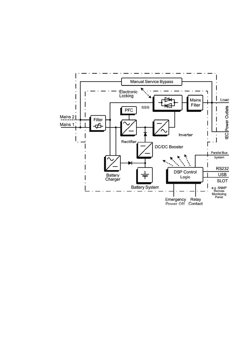
2.2 SYSTEM DESCRIPTION
The UPS is connected between the public network and the power load segment
to be protected.
The rectifier is powered from the mains and converts the AC voltage into a
stabilized DC voltage to feed the inverter. The circuitry technology used (PFC),
enables sinusoidal current consumption, thus allowing a low circuit feedback
operation. A separate, second rectifier (charger) based on switching power supply
technology, recharges or maintains the charge of the battery in the intermediate
circuit. Due to the special circuitry technology used in this charger / rectifier, the
harmonics of the charging current are reduced significantly. Additionally, a sleep
mode considerably increases the service life of the battery. The inverter converts
the DC voltage into a sinusoidal AC voltage. In combination with digital signal
processor technology and extremely high pulse rate IGBT-power semiconductors
in the inverter, a microprocessor-controlled regulator on the basis of pulse-width
modulation (PWM) guarantees a voltage system of the highest quality and
availability on the secured busbar.
Fig. 1: Component diagram

10
In the event of mains problems (e.g. power outages), power is supplied to the
load segment without an interruption from the inverter, which now uses the
battery. Since no switching is required, the load segment experiences no power
supply interruption at all.
The automatic bypass provides increased power supply security for single
installations in particular by switching the public network, e.g. in the event of
an inverter malfunction, through to the load segment directly and without
interruption. In other words, the automatic bypass provides the load segment
with an additional passive redundancy.
An integrated, manual bypass unit for maintenance and / or servicing provides an
uninterrupted supply of power to the consumers. The connection unit is designed
so that it can be separated from the UPS circuitry with minimal effort and can thus
remain in the rack. Through this simplified line-side activation, servicing of the unit
is possible at all times.
In order to ensure maximum security to the supply of the connected loads,
the equipment was also prepared for parallel operation: a second UPS system
provides maximum availability when used as an active redundancy. If, however,
the demand for power is in the foreground, then the second UPS can be used
for performance enhancing parallel operation.
The graphical LCD display used provides for versatile use and easy operation.
Convenient features such as switchable outputs, a freely programmable,
potential-free change-over contact, as well as an emergency power-off contact,
round out the standard interface selection (USB, RS232 and communication slot).

11
2.3 TECHNICAL DATA
Type rating
Protect D. 6000 6000 VA (cos ϕ = 0.9 lag) 5400 W
Protect D. 10000 10000 VA (cos ϕ = 0.9 lag) 9000 W
UPS input 1ph~ / N / PE (DUAL INPUT)
Nominal input voltage 200 / 208 / 220 / 230 / 240 Vac
Rectifier voltage range
(without battery operation,
100% load, cos ϕ = 0.9 lag)
176 Vac – 276 Vac
Rectifier voltage range
(without battery operation
50% power reduction)
120 Vac – 276 Vac
Bypass voltage range 184 Vac – 264 Vac
Frequency 50 Hz / 60 Hz (automatic detection or manually)
Frequency tolerance range ± 10%
Charging rate at full load
and battery charging (max.)
Protect D. 6000 29 A (U
N
=230 Vac)
Protect D. 10000 47 A (U
N
=230 Vac)
Circuit feedback factor λ ≥ 0.99 (THDi <5%)
UPS output
Nominal output voltage 200 / 208 / 220 / 230 / 240 Vac ± 1%
Power reduction at 200 Vac
Nominal output voltage: 10%
Nominal frequency 50Hz / 60Hz ± 0,5% (Tolerance in battery mode
or free running in frequency changer mode)
Synchronization range 50Hz or 60Hz ± 10%
Synchronization speed 1 Hz / s
Power factor range 0.5 lag to 0.9 cap. at full power output
Power reduction: 20% to 0.5 cap.
Frequency converter 20% power reduction
(Bypass deactivated, frequency range 40 – 70 Hz)
Waveform Sinus, distortion < 2% THD (linear load)
< 5% THD (non-linear load)
Crest factor 3:1

12
Overload behavior
with existing network
To 102% continuously;
≥ 102% – <130% for 2 min.
≥ 130% – <150% for 30 s
Automatic seamless transfer to bypass mode (SBS)
Overload behavior
Bypass
to 130% continuously;
≥ 130% – <180% for 1 min.
Overload behavior
when on battery
to 102% continuously;
≥ 102% – <130% for 10 s
≥ 130% for 100 ms
Short circuit protection 3 x I
N
for 100 ms
Battery
Autonomy time
Coupled
battery module
(cos ϕ = 0.9 lag / 100% charged battery / 25°C)
D. 6000
(rated load)
D. 6000
(half load)
D. 10000
(rated load)
D. 10000
(half load)
with integrated battery 3 min. 9.5 min. 4 min. 7.5 min.
1 add. battery module 11 min. 27 min. 9 min. 18 min.
2 add. battery modules 20 min. 46 min. 15 min. 30 min.
3 add. battery modules 30 min. 68 min. 21 min. 43 min.
4 add. battery modules 40 min. 91 min. 27 min. 57 min.
Battery check
(programmable):
Daily, weekly, monthly
Rated DC voltage
(DC Link)
Protect D. 6000 180 Vdc
Protect D. 10000 240 Vdc
Float voltage 2.28 Vdc / cell (default 20°C)
Charging voltage depending on temp.
Adjustment 2.21 Vdc / cell – 2.31 Vdc / cell in 0.01 V increments
Temperature compensation 20m V / 12 V-Block / °C
Battery charging current
(max.)
1.4 Adc (Protect D. 6000)
1.7 Adc (Protect D. 10000)
Switch-off
1.60 to 1.75 V / cell (load and temperature
dependent)

13
Battery voltage Visual and audible alarm at 1.90 V / cell
Type of battery Sealed lead-acid battery (VRLA)
spec. type for high-current discharge
Protect D. 6000 15 blocks at 12 V 5 Ah
Protect D. 6000 BP 15 blocks at 12 V 9 Ah
Protect D. 10000 20 blocks at 12 V 9 Ah
Protect D. 10000 BP 20 blocks at 12 V 9 Ah
Recharging times ~ 3h to 90% for internal battery
~9h / ~15h / ~21h / ~27h with 1 / 2 / 3 / 4 battery
extension(s)
Communication
Interfaces
(DUAL Monitoring)
RS232 (SUB-D (9-pin)), USB
Additional: communication slot for extensions
(e.g. relay card / SNMP (PRO), etc.)
EPO contact Potential-free
(optionally programmable as opener or closer)
Relay load-carrying ability 250 Vac 3 A or 30 Vdc 3 A change-over contact
(programmable)
Shutdown software on CD “CompuWatch” for all popular operating systems,
inc. Windows, Linux, Mac, Unix, Novell, Sun
General information
Classification VFI SS 111 acc. to IEC 62040–3
Double-conversion technology
Full-load efficiency
(AC-AC / DC-AC)
Protect D. 6000
Protect D. 10000
> 92% / >89%
> 93% / > 90%
Full-load efficiency
(ECO / transfer time < 10ms)
Protect D. 6000
Protect D. 10000
> 96%
> 97%
Inherent noise (1m distance) <55 dB(A)
Cooling External variable-speed cooling fan
Operating temperature range 0°C bis +40°C
Recommended: +15°C to +25°C
(battery system dependent)
Storage temperature range -15°C to + 60°C (UPS)
0°C to + 35°C (battery)

14
Humidity 0 - 95% (non-condensing)
Installation height Up to 1000 m at nominal power (for use above
1000 m, power loss is equal to 1% per 100 m)
Protection IP20
Connections
Mains connections
(DUAL or SINGLE)
Fixed connection (separate connections for
GR and bypass (bridged))
Consumer connections
with automatic locking
(in addition to standard
landline)
Protect D. 6000 2 x IEC320 C13
1 x IEC320 C19
Protect D. 10000 4 x IEC320 C19
Display Graphic LCD display, Resolution: 128 x 64 pixels
Languages: EN / DE / ES / FR / RU
incl. 3 LEDs for operating display
Housing color Black line with aluminum front
Weight (net / gross) Protect D. 6000 46 kg (20 kg without
battery) / 53 kg
Protect D. 10000 82.5 kg (32.5 kg without
battery) / 91 kg
Protect D. 6000 BP 44.5 kg / 53.0 kg
Protect D. 10000 BP 63.0 kg / 71.5 kg
Dimensions (net) Protect D. 6000 W 438 mm x D 715 mm x
H 132 mm
Protect D. 10000 W 438 mm x D 715 mm x
H 220 mm, Depth with
front cover plus 35mm
In combination with the mounting brackets,
a standard rack measures 19" = 482.6 mm.
Height: 3U (6 kVA) / 5U (10 kVA)
D. 6000 BP &
D. 10000 BP
W 438 mm x D 595 mm x
H 132 mm, (depth
including the front panel)

15
Dimensions
(gross (packaged))
Protect D. 6000 W 580 mm x D 800 mm x
H 540 mm
Protect D. 10000 W 580 mm x D 800 mm x
H 675 mm
Protect D. 6000 BP W 580 mm x D 800 mm x
H 355 mm
Protect D. 10000 BP W 580 mm x D 800 mm x
H 355 mm
Guidelines
The Protect D. complies with the EN 62040
product standard.
The CE seal on the device confirms compliance
with the EG Low Voltage Directive 2006 / 95 / EG
and EMC Directive 2004 / 108 / EG for
electromagnetic compatibility, if the installation
instructions provided in this manual are followed.
For 2006 / 95 / EG Low Voltage Directive
Reference number EN 62040-1: 2008
For 2004 / 108 / EG EMC Directive
Reference number EN 62040-2: 2006 class C2
WARNING:
This is a category C2–UPS product. In a domestic
environment, this product may cause radio
interference, in which case the user may be
required to take additional measures.
16
3.1 GENERAL SAFETY INSTRUCTIONS
Read these operating instructions carefully before using the UPS Protect D. and
its external battery modules (special accessories) for the first time; pay careful
attention to the safety precautions!
Use this device for its intended purpose only and in accordance with the safety
instructions and danger warnings in this instruction manual! The device is to be
used only when it is in perfect working condition; correct any problems that may
affect the safety of the device immediately.
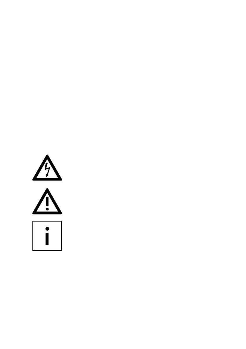
The following pictograms appear in this manual:
NOTE: DANGER!
In the case of danger to life and limb of the operator.
NOTE: ATTENTION!
Risk of injury and / or risk of damage to equipment and equipment parts.
NOTE: INFORMATION!
Useful and important for the operation of the UPS and the external battery
modules (optional).
3.2 SAFETY INSTRUCTIONS FOR THE PROTECT D.
This chapter contains important safety instructions for the UPS Protect D. and
its external battery modules (optional accessories) that must be followed for the
mounting, operation and maintenance of the uninterruptible power supply and
the battery system (internal and external batteries, if applicable).
3. SAFETY REGULATIONS
17
The UPS is an electrical device that can be dangerous. The device should only
be opened by qualified personnel. Repairs should only be carried out by
qualified service personnel!
The output can also be electrically charged, even if the UPS is not connected to
the mains power supply. The UPS has its own internal power supply (battery)!
To ensure operator safety, the device must be properly grounded!
The Protect D. must only be connected and operated with a VDE-approved
power cord with a grounding conductor to 200 V / 208 V / 220 V / 230 V / 240 V AC
voltage networks with a protective ground.
CAUTION – RISK OF BURNS!
The battery has a high short-circuit current. Connection or disconnection errors
can lead to the melting of plug connections, to arcing and to severe burns!
The device is equipped with a warning signal that sounds when the Protect D.
battery is discharged or when the UPS is not working in the normal mode (see
also chapter 9.1.1 “Alarm- / error messages”, from page 61).
To ensure the safe operation and reliability of the UPS and battery modules
(optional), observe the following safety instructions:
• Do not attempt to open the UPS! (The UPS does not contain any parts that
require regular maintenance. Please note that if the UPS has been opened,
any warranty claims with be voided)
• Do not expose the device to direct sunlight or a direct heat source!
• The unit is designed for installation in temperature controlled indoor rooms.
Do not install the device close to water or in very humid areas!
• If the UPS is brought from a cold environment into the installation area,
condensation may occur. Before using the UPS, it must be absolutely dry;
therefore a waiting time of a minimum of two hours before use is required.
• Never connect the mains power input with the UPS output!
18
• Ensure that no liquids or foreign objects enter the housing!
• Do not block the ventilation openings of the device! Make sure, for example,
that children do not insert anything into the ventilation openings!
• Never connect any household appliances, e.g. a hair dryer, to the UPS!
Also be careful when operating the device with power loads. Any feedback to
the inverter, e.g. due to a short-term generator operation of the load, must be
avoided at all costs.
• The power outlet should be located near the unit and with easy access in order
to make it easier to deactivate the AC input or pull out the plug!!
• While the device is in operation, do not pull the plug from the UPS or from
the network power supply outlet (grounded power outlet). This will cancel the
ground for the UPS and all of the load segments connected.
Danger of electric shock!
Even when the mains power supply has been disconnected, parts inside the
UPS are still connected to the battery and can give you an electric shock. Before
attempting any maintenance or service work, always disconnect the battery circuit!
Battery replacement and servicing must be done or at least supervised by a
qualified technician, who is familiar with the batteries and the safety precautions
that have to be taken!
Do not allow unauthorized access to the batteries!
When replacing the batteries, please note: Use only identical, maintenance-free,
valve regulated lead acid batteries with exactly the same specification as the
original batteries. Ask your AEG dealer for the appropriate battery tray.
Danger of explosion!
Do not dispose of batteries in an open fire.
Do not attempt to open or interfere with the batteries (the electrolytes released
will harm skin and eyes and can also be toxic!)
Batteries can cause electrical shock and high short circuit current.

19
Whenever you work with batteries, please take the following precautions:
• Remove all watches, rings and any other metallic jewelry!
• Use only tools with insulated handles!
Do not use connecting blocks with central on / off switches to prevent switch-on
current peaks.
Switch the UPS to “OFF” if you don’t want to use it for a longer period of time.
If your company switches off the power, then the Protect D. has to be switched
off as well. Otherwise, the battery will run down. To prolong battery life, avoid
running the battery down frequently!
For your own protection, never switch on the UPS when the plug has been pulled
from the Protect D.!
20
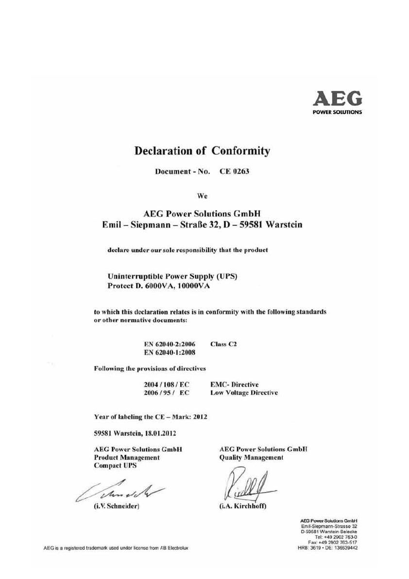
3.3 CE CERTIFICATE
/