Salicru SLC-2000-TWIN User manual
- Type
- User manual

SLC TWIN
INDEX
USER’S MANUAL FROM 0.7 kVA TO 3 kVA ....... Page 2
USER’S MANUAL FROM 4 kVA TO 20 kVA ........ Page 34

UNINTERRUPTIBLE POWER SUPPLY (UPS) + VOLTAGE STABILIZERS AND POWER LINE CONDITIONERS + SWITCH MODE POWER SUPPLY + INDUSTRIAL POWER SUPPLY + LIGHTING FLOW DIMMER STABILIZERS + STATIC INVERTERS
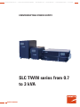
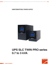
SLC TWIN series from 0.7
to 3 kVA
USER’S MANUAL
UNINTERRUPTIBLE POWER SUPPLY


3
SALICRU
GENERAL INDEX
1. INTRODUCTION.
1.1. GRATEFULNESS LETTER.
1.2. USING THIS MANUAL.
1.2.1. Used symbols and conventions.
1.2.2. For further information and/or help.
2. QUALITY AND STANDARD GUARANTEING.
2.1. MANAGEMENT DECLARATION.
2.2. STANDARD.
2.3. SAFETY AND FIRST AID.
2.4. ENVIRONMENT.
3. PRESENTATION.
3.1. VIEWS.
3.1.1 Views and legends.
3.1.2. Rears, description and connectivity.
3.1.4. Control panel.
3.2. DEFINITION AND STRUCTURE.
3.2.1. Nomenclature.
3.2.2. Structural diagram
3.3. SYSTEM DESCRIPTION.
3.3.1. Operating principle.
3.4. OPTIONAL.
3.4.1. Integration into IT networks through the SNMP adaptor (C16).
3.4.2. AS400 card (C16).
3.4.3. USB port card (C16).
3.4.4. Protocolo MODBUS.
4. INSTALLATION.
4.1. IMPORTANT SAFETY INSTRUCTIONS..
4.1.1. Transport.
4.1.2. Localiton.
4.1.3. Take care of your safety.
4.1.4. Operating.
4.1.5. Maintenance, service and faults.
4.2. TO KEEP IN MIND.
4.3. UNPACKING AND CONTENT CHECKING.
4.4. CONNECTION OF THE INPUT, OUTPUT AND PROTECTIVE EARTH
WIRING.
4.4.1. Notes for installing.
4.4.2. Installation.
4.4.3. Procedure to connect the models with external batteries, extended
autonomies.
4.5. COMMUNICATION PORTS..
4.5.1. RS-232 interface (C7).
4.5.2. AS400 interface (C16) (Option).
4.6. OVERVOLTAGE PROTECTION (FAX, MODEM, ...), CONNECTORS
RJ-45 (C12) AND (C13) FOR ETHERNET NETWORK.
4.7. SOFTWARE.
5. OPERATING.
5.1. OPERATING MODE.
5.1.1. Starting up the UPS with mains voltage (on Line mode).
5.1.2. Starting up the UPS without mains voltage (on Battery mode).
5.1.3. UPS shutdown with mains voltage (on Inverter mode).
5.1.4. UPS shutdown without mains voltage (on Battery mode).
5.1.5. Battery test function.
5.1.6. Alarm silencer.
5.2. CONTROL PANEL.
5.2.1. No output mode, code «00».
5.2.2. Bypass mode, code «01».
5.2.3. Line mode.
5.2.4. Battery mode / Battery test mode.
5.2.5. Fault mode.
5.2.6. Settings through the LCD panel.
6. MAINTENANCE, WARRANTY AND SERVICE.
6.1. BATTERY MAINTENANCE.
6.2. NOTES FOR INSTALLING AND REPLACING THE BATTERY.
6.3. TROUBLESHOOTING GUIDE.
6.4. WARRANTY CONDITIONS.
6.4.1. Covered product.
6.4.2. Warranty terms.
6.4.3. Out of scope of supply.
6.5. DESCRIPTION OF THE AVAILABLE MAINTENANCE CONTRACTS
AND SERVICE.
6.5. TECHNICAL SERVICE NETWORK.
7. ANNEXES.
7.1. TECHNICAL SPECIFICATIONS.
7.2. GLOSSARY.

4
SALICRU
1. INTRODUCTION.
1.1. GRATEFULNESS LETTER.
We would like to thank you in advance for the trust you have placed in
us by purchasing this product. Read this instruction manual carefully
before starting up the equipment and keep it for any possible future
consult that can arise.
We remain at you entire disposal for any further information or any
query you should wish to make.
Yours sincerely,
The equipment here described can cause important phys-
ical damages due to wrong handling. Due to this, the main-
tenance and/or fixing of the here described equipment must
be done by SALICRU staff or specifically authorised.
According to our policy of constant evolution, we reserve
the right to modify the specifications in part or in whole
without forewarning.
All reproduction or third party concession of this manual is
prohibited without the previous written authorization of our
firm.
1.2. USING THIS MANUAL.
The purpose of this manual is to provides explanations and proce-
dures for the installation, commissioning, maintenance and trou-
bleshooting of UPS from SLC TWIN series. This manual has to be
read carefully before installing and operating it. Keep this manual
for future consults.
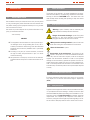
1.2.1. Used symbols and conventions.
«Warning» symbol. Carefully read the indicated para-
graph and take the stated prevention measures.
«Danger of electrical discharge» symbol. Pay special
attention to it, both in the indication on the equipment
and in the paragraph referred to this user’s manual.
i
«Main protective earthing terminal» symbol. Connect the
earth cable coming from the installation to this terminal.
i
«Notes of information» symbol.
Preservation of the environment: The presence of this
symbol in the product or in their associated documentation
states that, when its useful life is expired, it will not be disposed
together with the domestic residuals. In order to avoid possible
damages to the environment, separate this product from other re-
siduals and recycle it suitably. The users can contact with
their provider or with the pertinent local authorities to be informed
on how and where they can take the product to be recycled and/or
disposed correctly.
1.2.2. For further information and/or help.
For further information and/or help on the version of your specific
unit, request it to our Service and Technical Support department
(S.T.S.).
USER MANUAL

5
SALICRU
2. QUALITY AND STANDARD GUARANTEING.
2.1. MANAGEMENT DECLARATION.
Our target is the client’s satisfaction, therefore this Management has
decided to establish a Quality and Environmental policy, by means
of installation a Quality and Environmental Management System
that becomes us capable to comply the requirements demanded by
both the standards ISO 9001:2000 and ISO 14001:2004 and our
Clients and concerned parts too.
Likewise, the SALICRU Management is committed with the devel-
opment and improvement of the Quality and Environmental Man-
agement System, through:
The communication to all the company about the importance •
of satisfaction both in the client’s requirements and in the legal
and regulations.
The Quality and Environmental Policy diffusion and the fixation •
of the Quality and Environment targets.
To carry out revisions by the Management.•
To provide the needed resources.•
Management agent
The Management has designated as management agent the person
in charge about the Quality and Environment department, who with
independence of other responsibilities, has the responsibility and
authority: to assure that the processes of the quality and environ-
mental management system are established and maintained; to
inform to the Management about the operating of the quality and
environmental management system, including the necessities for
the improvement; and to promote the knowledge of the client’s
requirements and environmental requirements at all levels of the
organization.
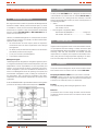
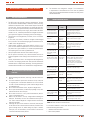
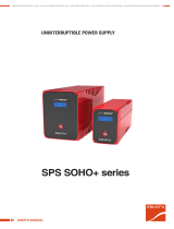
In the next PROCESS MAP is represented the interaction among all the
processes of the Quality and Environmental System of SALICRU:
2.2. STANDARD.
The UPS product SLC TWIN series is designed, manufactured and
commercialized in accordance with the standard EN ISO 9001 of
Quality Assurance. The marking shows the conformity to the EEC
Directive (quoted between brackets) by means of the application of
the following standards:
• Safety:
220V models: IEC/EN62040-1-1
110V models: UL1778
Electromagnetic compatibility (EMC): •
220V models: IEC/EN62040-2
..........................Category C1
110V models:: FCC PART 15
.....................................Class B
2.3. SAFETY AND FIRST AID.
Together with the equipment and this «User and installation manual»,
it is provided the information relating to «Safety instructions» (See
document EK266*08). Before proceeding to the installation or com-
missioning, check that both information are available; otherwise
request them. It is compulsory the compliance of the «Safety instruc-
tions», being the user the legal responsible regarding to its observ-
ance. Once read, keep them for future consults that can arise.
2.4. ENVIRONMENT.
This product has been designed to respect the environment and has
been manufactured in accordance with the standard ISO 14001.
Recycling the UPS SLC TWIN series at the end of its useful life:
SALICRU commits to use the services of authorised societies and
according to the regulations, in order to treat the recovered product
at the end of its useful life (contact your distributor).
Packing:
To recycle the packing, follow the legal regulations in force.
Batteries:
The batteries mean a serious danger for health and environment.
The disposal of them must be done in accordance with the stand-
ards in force..
Fig. 0. Process map

6
3. PRESENTATION.
This manual describes the installation and operating of the
SALICRU Uninterruptible Power Supply (UPS) of SLC TWIN se-
ries. The UPSs SLC TWIN series ensure an optimal protection for
any critical load, keeping the AC mains to the loads between the
requested parameters and with no-break, during the fault, deterio-
ration or fluctuations of the electrical commercial mains and with
the available models (from 0.7 kVA to 3 kVA) allow adapting the
model the end-user’s needs.
The UPS design and construction from SLC TWIN series has been
done in accordance with the international standards and also they
can be supplied in 19’’ rack format.
Thanks to the PWM (Pulse Width Modulation) technology used in
the UPSs of SLC TWIN series, they are compacts, colds, silent and
with high efficiency.
Therefore, this series has been designed to maximize the availability
of the critical loads and to ensure that your business is protected
from fluctuations of voltage, frequencies, electrical noises, black-
outs and mains faults, which are present in the energy distribu-
tion mains. This is the essential target of the UPSs of SLC TWIN
series.
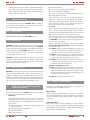
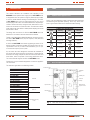
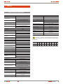
This manual is applicable to the following models:
Model Power (VA) Type
SLC-700-TWIN 700 Standard
SLC-1000-TWIN 1000
SLC-1500-TWIN 1500
SLC-2000-TWIN 2000
SLC-3000-TWIN 3000
SLC-700-TWIN B1 700 Standard with
extended autonomy
SLC-1000-TWIN B1 1000
SLC-1500-TWIN B1 1500
SLC-2000-TWIN B1 2000
SLC-3000-TWIN B1 3000
SLC-700-TWIN R 700 Rack 19”
SLC-1000-TWIN R 1000
SLC-1500-TWIN R B0 1500
SLC-2000-TWIN R B0 2000
SLC-3000-TWIN R B0 3000
SLC-700-TWIN R B1 700 Rack 19” with
extended autonomy
SLC-1000-TWIN R B1 1000
SLC-1500-TWIN R B1 1500
SLC-2000-TWIN R B1 2000
SLC-3000-TWIN R B1 3000
Table 1. Standarized basic models
3.1. VIEWS.
3.1.1 Views and legends.
Symbols and their meaning
Symbol Meaning Symbol Meaning
Warning Earth
Hihg voltage Silenced alarm
UPS ON / Battery
test
Overload
UPS OFF Battery
UPS on standby
or shutdown
Recycling
Alternating (AC)
Keep the UPS in a
cooled place
Direct (DC)
Table 2. Symbols used in the equipment and/or this manual.
USER MANUAL

7
SALICRU
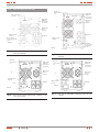
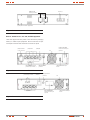
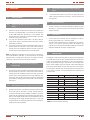
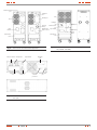
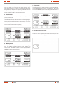
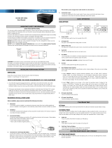
3.1.2. Rears, description and connectivity.
(C16) AS400/
SNMP/USB
Communication
port (optional)
(C2) Extended
autonomy
connector
(C4) Outlets
(C0) Inlet
(M1) Input breaker
protection
Fan
(C7) Communications
port RS232
(C11) and (C12)
Transient protection (fax,
modem,...)
Rear view SLC-700 and 1000-TWIN / -TWIN B1 to 208 / Fig. 1.
220 / 230 / 240 VAC
(C2) Extended
autonomy
connector
(C16) AS400/
SNMP/USB
communication
port (optional)
(C4) Outlet
(C0) Inlet
(M1) Input breaker
protection
Fan
RJ-45
(C7) RS232
communication
port
Rear view SLC-700 and 1000-TWIN / -TWIN B1 to 110 / Fig. 2.
115 / 120 / 127 VAC
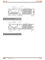
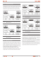
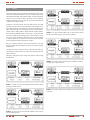
(C2) Extended
autonomy
connector
(C16) AS400/
SNMP/USB
communication
port (optional)
(C11) and
(C12) Transient
protection (Fax,
modem, ...)
(C4) Outlet
(C0) Inlet
(M1) Input breaker
protection
Fan
(C7) RS232
communication
port
Rear view SLC-1500 and 2000-TWIN to 208 / 220 / 230 Fig. 3.
/ 240 VAC
(C2) Extended
autonomy
connector
(C16) AS400/
SNMP/USB
communication
port (optional)
(C4) Outlet
(C0) Inlet
(M1) Input breaker
protection
Fan
RJ-45
(C7) RS232
communication
port
Rear view SLC-1500-TWIN / -TWIN B1 to 110 / 115 / 120 Fig. 4.
/ 127 VAC

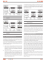
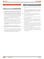
8
Extended
autonomy
connector cover
(C16) AS400/
SNMP/USB
communication
port (optional)
(C4) Outlet
(M1) Input breaker
protection
Fan
RJ-45
Fuses
(C7) RS232
communication
port
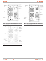
Rear view SLC-2000 and 3000-TWIN to 110 / 115 / 120 / Fig. 5.
127 VAC
(C2) Extended
autonomy
connector
(C16) AS400/
SNMP/USB
communication
port (optional)
(C11) and
(C12) Transient
protection (Fax,
módem, ...)
(C4) Outlet
(C0) Inlet
(M1) Input breaker
protection
Fan
(C7) RS232
communication
port
Rear view SLC-3000-TWIN to 208 / 220 / 230 / 240 VACFig. 6.
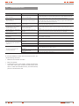
(C2) Extended
autonomy
connector
(C16) AS400/
SNMP/USB
communication
port (optional)
(C4) Outlet
(C0) Inlet
(M1) Input breaker
protection
Fan
RJ-45
Fuses
(C7) RS232
communication
port
Rear view SLC-2000 and 3000-TWIN / -TWIN B1 to 110 / Fig. 7.
115 / 120 / 127 VAC
USER MANUAL

9
SALICRU
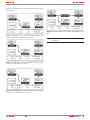
Rack 19” models for 208 / 220 / 230 / 240 VAC equipments
Later there appear the back panels of the SAI and the packaging
battery for 220Vac input equipments. All the conectores of input
and output and some other usefull one are in the rear panel.
(C2) Extended
autonomy connector
(C16) AS400/SNMP/
USB communication port
(optional)
(C7) Communication port
RS232
(M1) Input breaker protection
(C11) and (C12) Transient
protection (Fax, modem, ...)
(C4) Outlet
(C0) Inlet
Fan
Rear view SLC-700 and 1000-TWIN R / TWIN R B1Fig. 8.
(C2) Extended
autonomy connector
(C16) AS400/SNMP/USB
communication port (optional)
(C7) Communication
port RS232
(M1) Input breaker
protection
(C11) and (C12)
Transient protection (Fax,
modem, ...)
(C4) Outlets
(C0) Inlet
Fans
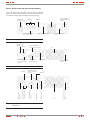
Rear view SLC-1500 and 2000-TWIN RFig. 9.
(C2) Extended autonomy
connector
(C16) AS400/SNMP/
USB communication port
(optional)
(C7) Communications port
RS232
(C4) Output terminals cover
(M1) Input breaker
protection
(C11) and (C12) Transient
protection (Fax, modem, ...)
(C4) Outlet
(M4) Output fuse
(C0) Inlet
Fans
Rear view SLC-3000-TWIN R and 1500, 2000, 3000-Fig. 10.
TWIN R B1

10
(C2b) Extended
autonomy connector
Breaker (*)
(*) Only for the 110Vac equipments
Rear view battery module R modelsFig. 11.
Rack 19” models for 110 / 115 / 120 / 127 VAC equipments
Later there appear the back panels of the SAI and the packaging
battery for 110Vac input equipments. All the conectores of input
and output and some other usefull one are in the rear panel.
(C2) Extended au-
tonomy connector
(C16) AS400/SNMP/
USB
communication port
(optional)
(C7) Communication port
RS232
(M1) Input breaker
protection
(C11) and (C12) Transient
protection (Fax, modem, ...)
(C4) Outlets (C0) Inlet
Fan
Rear view SLC-700 and 1000-TWIN R B1Fig. 12.
(C16) AS400/SNMP/
USB
communication port
(optional)
(C7) Communication port
RS232
(M1)
Input breaker
protection
(C11) and (C12) Transient
protection (Fax, modem, ...)
(C4) Outlets
(C0) Inlet
Fan
Rear view SLC-1500-TWIN RFig. 13.
USER MANUAL

11
SALICRU
(C2) Extended autonomy
connector
(C16) AS400/SNMP/
USB
communication port
(optional)
(C7) Commu-
nication port
RS232
(M1)
Input breaker
protection
(C11) and (C12) Transient
protection (Fax, modem, ...)
(C4) Outlets
(C0) Inlet
Fans
Rear view SLC-1500-TWIN R B1Fig. 14.
(C2) Extended au-
tonomy connector
(C16) AS400/SNMP/
USB
communication
port (optional)
(C7) Commu-
nication port
RS232
(M1)
Input breaker
protection
Fuse
(C11) and (C12)
Transient protection
(Fax, modem, ...)
(C4) Outlets
Input/output
terminal
Fans
Rear view SLC-2000 and 3000-TWIN R B1Fig. 15.

12
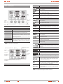
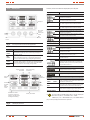
3.1.4. Control panel.
SELECT
button
ENTER
button
OFF
button
LCD
panel
ON / Alarm
silencer
button
Control panel. Tower type model.Fig. 16.
Button Function
ON button By pressing the ON button, the UPS starts up, the acoustic
alarm is deactivated and it is done a battery test.
OFF button By pressing the OFF button, the UPS goes to bypass
mode and the inverter is shutdown. From now on, if the
bypass and mains are active, the output terminals supply
voltage through themselves.
SELECT button The output voltage, frequency and the bypass enabling/
disabling can be selected if the UPS is on bypass mode
and by pressing the SELECT button and confirming by
pressing ENTER.
ENTER button
Table 3. Functions of each button.
Bypass operating information
Inverter operating infor-
mation
Output
informa-
tion
Load infor-
mation
Battery infor-
mation
Information
of the Mode/
Fault/War-
ning codes
Information to select the output voltage
and frequency and the bypass enabling
and disabling
Input infor-
mation
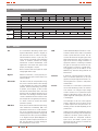
LCD panel descriptionFig. 17.
Display Function
Input information
V
AC
It displays the input voltage value, which will be showed
from 0 to 999 Vac
Hz
It displays the frequency value of the input voltage, which
will be showed from 0 to 99 Hz
H
It displays that the input voltage is higher than the SPEC
range and the UPS runs on battery mode.
L
It displays that the input voltage is lower than the SPEC
range and the UPS runs on battery mode.
Output information
V
AC
It displays the output voltage value, which will be showed
from 0 to 999 Vac.
Hz
It displays the frequency value of the output voltage, which
will be showed from 0 to 99 Hz.
Load information
It displays the % of the load in W or VA, the maximum value
will be showed from 0 to 199% only.
SHORT
It displays that the output is short-circuited and the UPS
could be shutdown.
OVERLOAD
It displays that the load overcomes the SPEC range.
Battery information
V
DC
It displays the battery voltage value, which will be showed
from 0 to 999 Vdc.
It displays the % of the battery capacity, which will be
showed from 0 to 199%
OVER CHARGE It displays that the battery is overcharged, and the UPS
could transfer to battery mode.
LOW It displays that the battery is low and the UPS could be
shutdown shortly.
Information of Mode/Fault/Warning codes
It displays the UPS operating mode. It will show the Mode/
Fault/Warning codes, which are identified in table 8 of
chapter 5.
Inverter operating information
It displays that the inverter is running.
Bypass operating information
It displays that the bypass is activated.
Information of output voltage and frequency and bypass enabling /
disabling
110V
AC
, 115V
AC
,
120V
AC
, 127V
AC
208V
AC
, 220V
AC
,
230V
AC
, 240V
AC
They are the eight selectable output voltage values with
the UPS on standby or bypass mode. One of them can be
activated at the same time only..
50 Hz
60 Hz
They are the two selectable frequency values of the output
voltage with the UPS on standby or bypass mode. One of
them can be activated at the same time only.
Bypass disable
Bypass enable
Selection of bypass enabled/disabled with the UPS on
standby or bypass mode. One of them can be activated at
the same time only.
Table 4. LCD panel messages and their functions
USER MANUAL

13
SALICRU
3.2. DEFINITION AND STRUCTURE.
3.2.1. Nomenclature.
KIT SLC-2000-TWIN A R (B1) 220/220 “EE29503”
Special equipment “EE”
Output voltage if it is not 220/230/240 Vac
Input voltage if it is not 220/230/240 Vac
(B0) Without batteries and without space
(B1) External batteries. The UPS has an extra charger
R Equipment in rack 19”
A Equipments with american voltages 110/120/127 Vac and connectors 5-15R
(onlydisponibleforequipments≤3kVA)
TWIN UPS mono-mono
Power in VA
KIT Equipments with two or more cabinets in one code
MOD BAT TWIN 2x3AB003 40A R W C0 “EE29503”
Battery module special “EE”.
CO Silk-screen printing “Made in Spain” in the equipment and packing customs topics
W White label team.
R Rack format.
Protection caliber.
Last three codes of the battery code.
Letters of the family of the battery code.
Amount of batteries of a single branch.
*x Amount of batteries in parallel. Omit for a single branch.
0/ Battery module without battery but with a cabinet and accessories.
TWIN Battery module series.
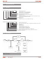
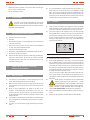
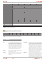
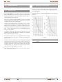
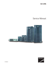
3.2.2. Structural diagram
I/P Mains
I/P EMI
FILTER
O/P EMI
FILTER
Battery
Charger
Battery
Inverter
Bypass
O/P
Controller
Power Supply
(SPS)
User Interface
Ventilation &
Chassis
PFC / Rectifier
Battery
Booster
DC
DC
DC
AC
AC
DC
Block diagramFig. 18.

14
3.3. SYSTEM DESCRIPTION.
3.3.1. Operating principle.
The UPS SLC TWIN series is a double conversion system AC/DC –
DC/AC, with battery. This structure is the one that provides a higher
reliability and protection to the output electrical power supply in
small and medium UPS power rates.
The input AC voltage is converted to DC by means of a diodes recti-
fier of full wave. The rectifier output is connected to the input of the
Power Factor Corrector (hereafter PFC).
The PFC boosts the DC voltage to optimal levels so the inverter
converts that DC voltage into an AC sinewave voltage, which is
stabilized in voltage and frequency, and ready to feed the loads.
The batteries are connected to the PFC input through a thyristor of
medium power, for those cases that their energy is needed (mains
fault or energy with poor quality).
The battery charger takes the energy from the PFC output (for
equipments with standard autonomy), and adapts it to the optimal
levels of the battery bank to charge.
This double conversion structure is complemented with a bypass
switch. The bypass switch is made by two relays, one for the by-
pass line and the second one (contactor depending on the power)
for the inverter line, connects the output load with the bypass line
directly in those special conditions like overloads, overtempera-
tures, etc. And they are connected to the inverter again when the
normal conditions are restored.
3.4. OPTIONAL.
Depending on the chosen configuration, your equipment could in-
clude any of the following optional:
3.4.1. Integration into IT networks through the SNMP
adaptor (C16).
The big IT systems based on LANs and WANs that make up servers
with different operating systems has to include the control and
management help at the managing system disposal. This help is got
through the SNMP adaptor, which is universal accepted by the main
software and hardware manufacturers.
The available SNMP optional for SLC TWIN series is card type,
in order to be inserted into the slot that UPS has in its rear side.
Thanks to this format, it is avoided to have small devices around
the UPS.
The connection from the UPS with the SNMP is internal, meanwhile
the one from the SNMP to the IT network is done through a RJ45
10-base connector.
3.4.2. AS400 card (C16).
The main target of the AS400 card is to transmit digital signals with
no potential for any use depending on the application. The most
common application of this kind of interface is the automatic closing
file and the computer shutdown later on, including the UPS.
The signals provided by the card in dry contact format are:
UPS fault (NO; normally open)•
General alarm (NC; normally closed)•
UPS on bypass (NC)•
Low battery alarm (NO)•
UPS on inverter (NO)•
Mains fault alarm (NO)•
Besides there is an input to shutdown the equipment remotely.
3.4.3. USB port card (C16).
The UPS SLC TWIN series has a USB port card as an option, which
converts the traditional RS-232 port with DB9 format into a USB
port (Universal Series Bus) type B.
This allows connecting the UPS with a personal computer (PC)
easily. The format of the USB optional is card type. It allows being
inserted into the slot that the UPS has available in its rear side.
3.4.4. Protocolo MODBUS.
The big IT systems based on LANs and WANs, many times require
that the communication with any element that is integrated inside
the IT network is carried out by means of an industrial standard
protocol.
One of the industrial standard protocols more used in the market is
the MODBUS protocol. The SLC TWIN series is also ready to be
integrated in this type of environments through the external Win-
power CMC card, which is used for the interface to implement
the remote/monitor function without the computer direct commu-
nicate to the UPS. Without install the WinPower software, you are
not able to monitor/control the UPS through the LAN. Here is the
connection for the CMC card. Owing to the connection is in series,
once the cable is disconnected within the UPS connection, all the
UPS after that connection will all lose the communication
USER MANUAL

15
SALICRU
4. INSTALLATION.
4.1. IMPORTANT SAFETY INSTRUCTIONS..
Read the following safety instructions before installing
and starting up the equipment.
4.1.1. Transport.
Transport the UPS in the original packing (as protection from •
jolts and impacts).
4.1.2. Localiton.
Condensation problems could happen when moving the UPS •
from cold area to heat one. The UPS has to be perfectly dry be-
fore installing. Two hours of acclimatization should be allowed
as minimum.
Do not install the UPS close to water, wet or dust environ-•
ments.
Do not install the UPS in places exposed to direct sunlight or •
close to heat sources.
Do not block the cooling wholes of the UPS enclosure.•
4.1.3. Take care of your safety.
Equipment definition.•
Movable installation, class I, fed by an outlet type A and distri-
bution system TT (neutral regime is referred to earth).
Equipment with terminals: Fix installation, class I, permanent
connected and TT distribution (neutral regime is referred to
earth)
• The UPS can be connected and handled by staff
without any specific training, less those hardwired
models that will be installed by qualified staff and in
accordance with the regulations in force.
• Do not forget that the UPS is a generator of electric
energy, therefore the user has to take the needed
cautions against direct and indirect contacts.
Do not connect devices or loads at its outlets that can overload •
the UPS, like laser printers.
Put the cables in order to avoid tripping or stepping with them.•
Do not overload the equipment with domestic loads like hair-•
dryers, irons, etc...
The earth connection must be wired to the protection earth la-•
belled as ( ), making sure that it is done before turning on
the input voltage. For small devices (connected with power
cord with plug), the user has to make sure that the outlet cor-
responds with the supplied type, with earth connection com-
pletely isolated and connected to the local protective earth.
The UPS plug connected to the mains outlet, will have easy ac-•
cess and close to the equipment.
In those models with terminals a disconnection device has to be •
installed, with easy access and close to the equipment.
To connect the UPS to the mains and loads, use standardized •
cables and tested by an official organization only.
When installing the equipment, make sure that the sum of the •
earth leakage currents at the UPS output plus the connected
load/s do not overcome 3,5 mA.
4.1.4. Operating.
Do not disconnect the power cord plug of the UPS meanwhile •
the loads are turned on, because the earth connections of the
equipment and loads will be disconnected.
The UPS is characterized for having an internal current power •
supply (batteries). The UPS outlets can be alive electrically
although the UPS is disconnected from the installation of the
building physically.
Pay special attention to the labelling of the equipment that •
warns on «Electrical discharge danger» and stated as ( ).
Inside the equipment there are dangerous voltages, do not open •
the case, the access has to be done by authorised and compe-
tent staff. In case of maintenance or fault, consult the closest
STS (Service and Technical Support).
To disconnect the UPS completely, first press the OFF button, •
then disconnect the power cord cable in those models with plug
or turn Off the disconnection device close to the equipment (to
be installed and property by the customer), in those models
with terminals.
Make sure that objects or fluids cannot enter inside the UPS.•
4.1.5. Maintenance, service and faults.
The UPS works with dangerous voltages. The repair has to be •
done by qualified staff only.
Electrical shock risk. Although the unit is discon-
nected from the electrical mains, there are internal
parts in the UPS that are still connected to the bat-
teries, therefore they are both under voltage and dangerous.
Before doing any service and/or maintenance, disconnect the •
batteries and check that there is not any voltage in the termi-
nals capacitor bus (BUS-capacitors).
Only properly staff familiarized with the batteries and with the •
additional caution measures can replace them and supervise
the operations. Not authorized people should be kept away.
Electrocution risk. The battery circuit is not isolated
from the input voltage. Dangerous voltages can exist
between the battery and earth terminals. Before
touching, check that there is not any voltage present.
The batteries can cause electrocution and to produce a high •
shot-circuit current. Take the caution measures stated below
when working with batteries:
Take watches, rings and any metallic object off.
Use tools with insulated handles only and gloves.
During battery replacement, install the same number and type.•
Do not catch fire to the batteries. Explosion danger.•
Do not open or destroy the batteries. Electrolyte spillage can •
hurt eyes and skin. It can be toxic.

16
Replace the fuse by another one with the same size and type •
only, in order to avoid fire risks.
Do not dismantle the UPS.•
4.2. TO KEEP IN MIND.
• The UPS can be wired and handled by non-trained
staff, less those models with terminals that will be
installed by qualified staff and in accordance with the
applicable safety regulations.
4.3. UNPACKING AND CONTENT CHECKING.
Unpack and check the content:1.
One UPS.•
Documentation relative to the equipment (user’s manual and •
warranty certificate).
One power cord to connect it to the mains and standardized •
for 16A, less those hardwired models.
One serial communication cable.•
One battery cable (Modules with extended autonomy only (B*)).•
One CD for monitoring software.•
Inspect the UPS with the purpose of detecting possible dam-
2.
ages due to the transport. Do not start up the unit and notify
immediately to the carrier and to your distributor if there is any
damaged or missing part.
4.4. CONNECTION OF THE INPUT, OUTPUT AND
PROTECTIVE EARTH WIRING.
4.4.1. Notes for installing.
The UPS has to be installed in a well-cooled place, far from 1.
water, inflammable gases and corrosive agents.
Make sure that the front and rear cooling wholes of the UPS
2.
are not blocked. Leave 0,2 metres of space around the UPS as
minimum.
Drops of water condensation can appear if the UPS is un-
3.
packed in a low temperature environment. In this case it is
necessary to wait until the total unit is dry before proceeding
to the installation and the starting up. Otherwise electrocution
danger will exist.
The installation and wiring have to be done in accordance with
4.
the local regulations and following the instructions of profes-
sional staff.
For safety, turn off the power supply before doing the instal-
5.
lation.
It is recommended to charge the batteries of the UPS for 1-2 6.
hours before its use. Once the input circuit breaker is turned
«On», the UPS will charge the batteries automatically. The
UPS can be used immediately without charging the batteries
previously, but the expected autonomy will be lower than the
standard value, being possible to be nil or almost nil.
4.4.2. Installation.
Insert the end of the power cord supplied with the equipment 1.
(end with female connector IEC 320), into the connector (C0)
of the UPS, make the suitable pressure to insert it correctly.
The power supply of the equipment has to be done through
2.
the supplied power cord (C1) and it has to be connected to an
outlet (socket) with both earth connection and easy access.
In case of requiring another power cord due to lose, ageing or
damage of the original one, replace it by a standardized one
with the same features.
Phase
(L)
Neutral
(N)
(PE)
Output terminal (C4)Fig. 19.
Connect the loads to the outlets (C4).3.
Some model depending on the power, has output terminals 4.
(C4) to feed the loads. To have access to them it is better to
remove the screws that fix the terminal cover, take it away and
next make the wiring connections by respecting the order of
the phase (L), neutral (N) and protective earth (PE) stated in
the labelling and figure 19. Finally put the terminal cover back
by fixing it with the respective screws.
The cross section of these cables will be taken from the nom-
inal currents stated in the nameplate of the equipment, by re-
specting the Local an/or National Low Voltage Electrotechnical
Regulation.
5. Under request, the equipment can be supplied with
different outlets (French, IEC, Schuko, UK, ...), which
are standardized for 10A current (IEC) or 16A (for the
rest). Do not overload the UPS and the outlets. The laser printers,
plotters, scanners or other peripheral devices with high con-
sumption do not have to be connected to the equipment.
When the installation is finished, make sure that the wiring is
6.
correct.
Install a circuit breaker at the UPS output if were needed.
7.
USER MANUAL

17
SALICRU
Model Power (VA) Nr outlets Output terminals
SLC-700-TWIN 700 2 -
SLC-1000-TWIN 1000 2 -
SLC-1500-TWIN 1500 3 -
SLC-2000-TWIN 2000 3 -
SLC-3000-TWIN 3000 3 -
SLC-700-TWIN B1 700 2 -
SLC-1000-TWIN B1 1000 2 -
SLC-1500-TWIN B1 1500 3 -
SLC-2000-TWIN B1 2000 3 -
SLC-3000-TWIN B1 3000 3 -
SLC-700-TWIN R 700 4 -
SLC-1000-TWIN R 1000 4 -
SLC-1500-TWIN R B0 1500 4 -
SLC-2000-TWIN R B0 2000 4 -
SLC-3000-TWIN R B0 3000 - 1 set (F+N)
SLC-700-TWIN R B1 700 4 -
SLC-1000-TWIN R B1 1000 4 -
SLC-1500-TWIN R B1 1500 - 1 set (F+N)
SLC-2000-TWIN R B1 2000 - 1 set (F+N)
SLC-3000-TWIN R B1 3000 - 1 set (F+N)
Table 5. Number of outlets and terminals depending on the
model
Never mind if the UPS is connected to any load, voltage could
8.
exist at its output. The internal parts of the equipment can
remain with voltage although the UPS is shutdown. Make sure
that there is no output voltage, disconnect the UPS and turn
off the input power supply in the electrical panel.
In case, it is needed to connect inductive loads to like laser
9.
printers, the inrush current of such loads should be calculated,
in order to determine if the UPS power rate is enough to supply
them.
4.4.3. Procedure to connect the models with external
batteries, extended autonomies.
Do not make any connection between the UPS and battery 1.
modules, when the equipment and/or loads are turned on.
The DC nominal voltage of the external battery pack is 36 V DC
2.
(3 batteries of 12 V) for 0,7 kVA and 1 kVA equipments, and
96 V DC (8 batteries of 12 V) from 1,5 to 3 kVA equipments.
To achieve a higher autonomy, it is possible to connect some
battery packs.
Before connecting the battery modules to each
other and/or UPS, check that they have the same
voltage and capacity, otherwise the difference of
potential will provoke a short-circuit, which will cause dam-
ages to the UPS and/or to the battery modules.
Any connection between the UPS and battery module/s will
3.
be done taking care on the stated polarity in the equipment
labelling and the colour of the cables (red for positive, black for
negative and green yellow for the earth cable).
The connection with the batteries, either because they are
4.
supplied separate from the equipment or due to UPS extended
autonomy, will be done through the connector (C2) of the
equipment and (C2b) of the own battery module. Each battery
module has two identical connectors duly polarised too. One
of them is for the UPS connection and the other one is for the
connection with another battery module.
Insert one end of the cable into the connector (C2) of the UPS
5.
and the other end of the cable into the connector (C2b) of the
battery module. It is possible to link some battery modules by
means of the two connectors that each external battery unit
has, so one connector has to be connected to the preceded
module and the other one to next.
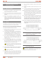
4.5. COMMUNICATION PORTS..
4.5.1. RS-232 interface (C7).
Pin # Description Input/Output
2
TXD Output
3
RXR Input
5 GND Input
Table 6. Pin-out of DB-9 connector (C7) RS232 interface
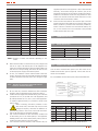
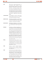
4.5.2. AS400 interface (C16) (Option).
Less the above communication protocol, this UPS series has an
AS400 communication protocol (optional). Contact with the dis-
tributor for more details.
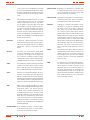
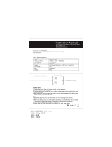
Pin-out and DB-9 connector description (C16) of the AS400 card.
UPS fault
General alarm
Ground (GND)
Remote shutdown
Common
Bypass
Low battery
UPS On
Mains fault
DB-9 connector (C16), AS400 interfaceFig. 20.
Pin # Description I/O Pin # Description I/O
1 UPS fault Output 6 Bypass Output
2 General alarm Output 7 Low battery Output
3 GND Input 8 UPS ON Output
4 Remote shutdown Input 9 Mains fault Output
5 Common Input
Table 7. Pin-out of DB-9 connector (C16), AS400 interface

18
4.6. OVERVOLTAGE PROTECTION (FAX, MODEM, ...),
CONNECTORS RJ-45 (C11) AND (C12) FOR ETHERNET
NETWORK.
This connection is not necessary to make for UPS operating, •
and it is only used for transient voltage protection.
Connect the input line (server side) of the communication net-•
work to the «Input» connector (C11).
Connect the output line (user side) to the communication net-•
work to the «Output» connector (C12).
i
The ETHERNET network, could not operate if it is connected
wrongly.
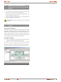
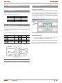
4.7. SOFTWARE.
Free software - WinPower.
WinPower is the brand of the new UPS monitoring software, which
facilitates a friendly monitoring and control interface. In case of
mains failure, this software gives an automatic Shutdown for a
system made by several PCs. With this software, the users can
monitor and control any UPS in the same Local Area Network LAN
without taking care about the distance among them.
Installation procedure:
Insert the supplied CD. The installation assistance will boot
1.
automatically. Follow the steps stated by itself.
When it is asked, enter the serial number written over the CD.
2.
When the PC reboots, the WinPower software will be showed as a
plug icon with green colour in the system tray, near to the clock.
Graphic screen of WinPower softwareFig. 21.
USER MANUAL

19
SALICRU
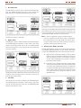
5. OPERATING.
5.1. OPERATING MODE.
5.1.1. Starting up the UPS with mains voltage (on Line
mode).
Check both all the connections have been done properly and 1.
the input circuit breaker (M1), is not turned off. This protecion
for SLC-3000 TWIN R is replaced by a circuit breaker, turn
«On» and also this model has an output fuse (M4), check that
is fitted in and in good conditions.
Turn «On» the distribution panel switch. The UPS could not
2.
supply power supply to the loads because the bypass mode is
deactivated, code «00».
Start up the inverter of the UPS by pressing the button «On» of
3.
the front panel for more than 1 second. The system will do an
autotest and once finished the inverter will start up and also
the UPS status will be displayed in the front LCD panel.
Note: By default the equipment is set from factory with the by-
pass mode disabled, code «00», so the loads will not be supplied
although there is voltage at the UPS input. To modify this factory
setting, go to section 5.2.6 and activate the code «01».
5.1.2. Starting up the UPS without mains voltage (on
Battery mode).
Start up the inverter of the UPS by pressing the button «On» of 1.
the front panel for more than 1 second. The system will do an
autotest and once finished the inverter will start up and also
the UPS status will be displayed in the front LCD panel. The
period time that the UPS will remain started up will depend
on the battery charging level and the loads connected at the
UPS output.
5.1.3. UPS shutdown with mains voltage (on Inverter mode).
Shutdown the inverter of the UPS by pressing the button «Off» 1.
in the front panel for more than 1 second. The UPS will go to
no output mode «00» -bypass disabled- (code 00) or on bypass
mode (code 01), depending if the initial setting has been modi-
fied or not. On bypass mode (code «01») the equipment will still
be supplying output voltage through the bypass, so the input
circuit breaker of the switchgear panel has to be turned off to
shutdown the loads completely.
5.1.4. UPS shutdown without mains voltage (on Battery
mode).
To shutdown the inverter of the UPS, just press the button 1.
«Off» of the front panel for more than 1 second. The UPS will
be turned off.
5.1.5. Battery test function.
To make a battery test with the equipment started up, press •
the button « I » of the front panel or disconnect the input power
supply to the UPS.
5.1.6. Alarm silencer.
To silent the alarm manually with the equipment on battery •
mode, press the button « I » of the front panel.
The alarm will automatically be activated when the battery
capacity is low (end of autonomy). When this happens, the
loads have to be turned off and the UPS shutdown, because the
equipment will break the output voltage in short.
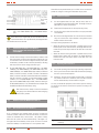
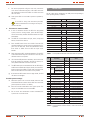
5.2. CONTROL PANEL.
The different codes of operating, fault or warning can be displayed
in the LCD panel of the synoptic, are described in the table 8. Some
codes can be displayed or activated at any time, corresponding to
modes of operating, warning or fault alarm or even though some
alarms of fault together. Each one of these codes will be displayed
in the screen of the display cyclically, less when one or more alarms
are activated. In the last case, the display will only show the alarm
or the alarms cyclically, not being displayed the operating and
warning modes.
Operating mode Code Operating mode Code
Operating code
No output mode 00 Battery mode 03
Bypass mode 01 Battery test mode 04
Line mode 02
Fault codes
Bus fault 05 Overload fault 07
Inverter fault 06 Overtemperature fault 08
Warning codes
Wiring error 09 Low battery 12
Fan or fans fault 10 Charger fault 13
Battery overvoltage 11
Table 8. Code list and their meaning
Page is loading ...
Page is loading ...
Page is loading ...
Page is loading ...
Page is loading ...
Page is loading ...
Page is loading ...
Page is loading ...
Page is loading ...
Page is loading ...
Page is loading ...
Page is loading ...
Page is loading ...
Page is loading ...
Page is loading ...
Page is loading ...
Page is loading ...
Page is loading ...
Page is loading ...
Page is loading ...
Page is loading ...
Page is loading ...
Page is loading ...
Page is loading ...
Page is loading ...
Page is loading ...
Page is loading ...
Page is loading ...
Page is loading ...
Page is loading ...
Page is loading ...
Page is loading ...
Page is loading ...
Page is loading ...
Page is loading ...
Page is loading ...
Page is loading ...
Page is loading ...
Page is loading ...
Page is loading ...
Page is loading ...
-
 1
1
-
 2
2
-
 3
3
-
 4
4
-
 5
5
-
 6
6
-
 7
7
-
 8
8
-
 9
9
-
 10
10
-
 11
11
-
 12
12
-
 13
13
-
 14
14
-
 15
15
-
 16
16
-
 17
17
-
 18
18
-
 19
19
-
 20
20
-
 21
21
-
 22
22
-
 23
23
-
 24
24
-
 25
25
-
 26
26
-
 27
27
-
 28
28
-
 29
29
-
 30
30
-
 31
31
-
 32
32
-
 33
33
-
 34
34
-
 35
35
-
 36
36
-
 37
37
-
 38
38
-
 39
39
-
 40
40
-
 41
41
-
 42
42
-
 43
43
-
 44
44
-
 45
45
-
 46
46
-
 47
47
-
 48
48
-
 49
49
-
 50
50
-
 51
51
-
 52
52
-
 53
53
-
 54
54
-
 55
55
-
 56
56
-
 57
57
-
 58
58
-
 59
59
-
 60
60
-
 61
61


Salicru SLC-2000-TWIN User manual
- Type
- User manual
Ask a question and I''ll find the answer in the document
Finding information in a document is now easier with AI
Related papers
-
Salicru SLC-8000 TWIN PRO User manual
-
 Salicru SPS.HOME User manual
-
 Salicru SPS.400.HOME User manual
-
Salicru SLC-700-TWIN RT (B1) User manual
-
 Salicru SLC-3000-TWIN PRO User manual
-
 Salicru SLC-700 TWIN PRO (B1) User manual
-
Salicru SLC.4000.TWIN Datasheet
-
 Salicru SPS.1500.ADV RT (B0) User manual
-
 Salicru SPS.2000.SOHO+ User manual
-
 Salicru SLC-1500 LINK User manual


Other documents
-
 PowerWalker VFI 60K CPT 3/3 BX Owner's manual
-
BlueWalker PowerWalker VI 2000RT LCD User manual
-
 Sprite AE7E-CM User manual
-
Repotec RP-UPH104T Owner's manual
-
Eaton 700VA User and Installation Manual
-
Eaton VA 700 Installation guide
-
 HITRENDS YA22WS-2AU5U User manual
-
AEG Protect 2.33 2.0 User manual
-
Eminent EM3990 Datasheet
-
 PowerWalker Inverter 650 SW Owner's manual


