Page is loading ...

Fusion NLT Hybrid
Water Softener with Chlorine and Chloramine
Removal
Visit us online at
www.uswatersystems.com
REVISION # 4.5
REVISION DATE May 12, 2015
US Water Systems Corporate Office
1209 Country Club Road
Indianapolis, IN 46234
1-800-608-8792
info@uswatersystems.com
Owners Manual
Models:
087-FNLT-XXX-HY1

2
Visit us online at www.USWaterSystems.com Give us a call at: 1-800-608-8792
Safety Guide
For your safety, the information in this manual must be followed to minimize the risk of elec-
tric shock, property damage or personal injury.
Be sure to check the entire softener for any shipping damage or parts loss. Also note dam-
age to the shipping cartons. Contact US Water Systems at 1-800-608-8792 to report any
shipping damage within 24 hours of delivery. Claims made after 24 hours may not be hon-
ored.
Small parts, needed to install the softener, are in a parts bag. To avoid loss of the small
parts, keep them in the parts bag until you are ready to use them.
Unpacking / Inspection
PAGE
Unpacking / Inspection 3
Safety Guide 3
Proper Installation 4
Specification 7
Before Starting Installation 7
Installation Instructions 18
System Start Up 27
Programming Instructions 28
About The System 29
Maintenance 31
Sanitizing Procedure 35
Main Repair Parts 36
Trouble Shooting 41
Programming Chart 42
Warranty 43
Table of Contents
Check and comply with your provincial /
state and local codes. You must follow
these guidelines.
Use care when handling the water soften-
ing system. Do not turn upside down, drop,
drag or set on sharp protrusions.
The water softening system works on 12
volt-60 Hz electrical power only. Be sure to
use only the included transformer.
Transformer must be plugged into an in-
door 120 volt, grounded outlet only.
Use clean water softening salts only, at
least 99.5% pure. Extra Course Grade or
Crystal salts are recommended. Do not
use rock, block, granulated or ice cream
making salts. They contain contaminants
that could cause maintenance problems.
Keep the salt lid in place on the softener
unless servicing the unit or refilling with
salt.
WARNING: This system is not intend-
ed for treating water that is microbiologi-
cally unsafe or of unknown quality without
adequate disinfection before or after the
system. Contact US Water Systems for
disinfection treatment equipment.

3
Proper Installation
This water softening system must be properly installed and located in accordance with the
Installation Instructions before it is used or the warranty will be void.
Do not install or store where it will be
exposed to temperatures below freezing or
exposed to any type of weather. Water
freezing in the system will break it. Do not
attempt to treat water over 100°F.
Do not install in direct sunlight. Exces-
sive sun or heat may cause distortion or
other damage to non-metallic parts.
Properly ground to conform with all gov-
erning codes and ordinances.
Use only lead-free solder and flux for all
sweat-solder connections, as required by
state and federal codes.
Maximum allowable inlet water pressure is
125 psi. If daytime pressure is over 80 psi,
night time pressure may exceed the maxi-
mum. Use a pressure reducing valve to
reduce the pressure.
Softener resins may degrade in the pres-
ence of chlorine or chloramines above 2
ppm. If you have chlorine or chloramines
in excess of this amount, you may experi-
ence reduced life of the resin. In these
conditions, you may wish to consider pur-
chasing a whole house carbon filter soften-
er system with a chlorine reducing media.
Contact US Water Systems for Chlorine
and Chloramine removal equipment. Fu-
sion Hybrid Water softeners can remove
chlorine.
WARNING: Discard all unused parts
and packaging material after installation.
Small parts remaining after the installation
could be a choke hazard.

4
Visit us online at www.USWaterSystems.com Give us a call at: 1-800-608-8792
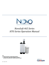
Inlet-Outlet
Connection
Height
Overall
System
Height
B
A
Model Tank Size A B C
FNLT-100-HY 9” X 48” 61 7/8” 50 7/8” 9”
FNLT-150-HY 10” X 54” 67 7/8” 57” 10”
FNLT-200-HY 12” X 52” 65 7/8” 55 1/4” 12”
FNLT-250-HY 13” X 54” 67 7/8” 57 5/8” 13”
System Dimensions
C
Tank
Diameter
CARBON TANK
SOFTENER TANK

5
System Dimensions
15” Brine
Tank
17.04

6
Visit us online at www.USWaterSystems.com Give us a call at: 1-800-608-8792
Specifications
Before Starting Installation
Tools, Pipe, and Fittings, Other Materials
Channel Locks
Screwdriver
Teflon tape
Razor knife
Two adjustable wrenches
Additional tools may be required if modifi-
cation to home plumbing is required.
Plastic inlet and outlet fittings are included
with the softener. To maintain full valve
flow, 1” pipes to and from the softener fit-
tings are recommended. You should main-
tain the same, or larger, pipe size as the
water supply pipe, up to the softener inlet
and outlet.
Use copper, brass, or PEX pipe and fit-
tings.
Some codes may also allow PVC plastic
pipe.
ALWAYS install the included bypass valve,
or 3 shut-off valves. Bypass valves let you
turn off water to the softener for repairs if
needed, but still have water in the house
pipes.
5/8” OD drain line is needed for the valve
drain.
A length of 5/8” OD drain line tubing is
needed for the brine tank over flow fitting
(optional).
Extra Course Grade or Crystal water sof-
tener salt is needed to fill the cabinet or
brine tank.
Continuous operation at flow rates greater than the service flow rate may affect capacity and efficiency performance.
The manufacturer reserves the right to make product improvements which may deviate from the specifications and
descriptions stated herein, without obligation to change previously manufactured products or to note the change.
The above capacity and flow rate specifications have not been validated by WQA.

7
Where To Install The Softener
How Your Water Conditioner Works
The principle behind water softening is simple chemistry. A water softener contains resin
beads which hold electrically charged ions. When hard water passes through the softener,
calcium and magnesium ions are attracted to the charged resin beads. The result is remov-
al of calcium and magnesium ions which produces soft water.
This system is controlled with simple, user-friendly electronics displayed on a LCD screen.
The main page displays the current time and the remaining gallons in meter mode or the re-
maining days in calendar clock mode. The system will also scroll through other pertinent
information.
Place the softener as close as possible to
the pressure tank (well system) or water
meter (city water).
Place the softener as close as possible to
a floor drain, or other acceptable drain
point (laundry tub, sump, standpipe, etc.).
Connect the softener to the main water
supply pipe BEFORE the water heater.
DO NOT RUN HOT WATER THROUGH
THE SOFTENER. Temperature of water
passing through the softener must be less
than 100 deg. F.
Outside faucets and irrigation systems
should be supplied with hard water prior to
the water softener.
Do not install the softener in a place where
it could freeze. Damage caused by freez-
ing is not covered by the warranty.
Put the softener in a place water damage
is least likely to occur if a leak develops.
The manufacturer will not repair or pay for
water damage.
A 120 volt electric outlet is needed within 6
feet of the softener. The transformer has
an attached 6 foot power cable. Be sure
the electric outlet and transformer are
in an inside location, to protect from
wet weather.
If installing in an outside location, you must
take the steps necessary to assure the sof-
tener, installation plumbing, wiring, etc. are
protected from the elements and contami-
nation sources.
Keep the softener out of direct sunlight.
The sun’s heat may soften and distort
plastic parts.
FUSION NLT
HYBRID WATER SOFTENER

8
Visit us online at www.USWaterSystems.com Give us a call at: 1-800-608-8792
Softener Preparation
Fusion NLT Tank Installation Instructions
WATER PRESSURE: A minimum of 20 pounds of water pressure is required for regeneration valve
to operate effectively.
ELECTRICAL FACILITIES: An uninterrupted alternating current (A/C) supply is required. Note: Other
voltages are available. Please make sure your voltage supply is compatible with your unit before installation.
EXISTING PLUMBING: Condition of existing plumbing should be free from lime and iron buildup.
Piping that is built up heavily with lime and/or iron should be replaced.
LOCATION OF FUSION NLT TANK AND DRAIN: The Infusion tank should be located close to a drain
to prevent air breaks and back flow.
CAUTION: Water pressure is not to exceed 80 psi, water temperature is not to exceed 110°F (43°C),
and the unit cannot be subjected to freezing conditions.
Media Installation
1) Remove the tank from carton.
2) Verify the riser tube is centered in the bottom center of the tank. A flashlight may be
necessary.

9
Softener Preparation
3) Place a piece of duct tape over the riser tube of one of the tanks, so no gravel or carbon
enters the riser while filling. Both tanks are the same and it does not matter which tank is
used for the carbon and which tank is used for the softening resin. Gravel will be poured in
the carbon tank ONLY.
4) Use the Blue Funnel provided, to pour the gravel and carbon into the tank. Pour it evenly
around the hole to ensure it is well distributed in the tank and pour slow enough, to keep
from plugging the hole. The gravel should be poured in the tank first, then pour the carbon
in the tank second. Pour all the gravel and carbon that was shipped in the tank. A helper
may be needed to hold the funnel during the filling process. It is recommended that a dust
mask and safety goggles be worn to prevent possible injury.
5) Once the carbon tank has been loaded with gravel and carbon, remove the duct tape
and funnel and fill the tank with water (if possible/practical) and let it soak. This will de-
crease the rinse time needed to remove the carbon fines/dust during startup. If this cannot
be done, the rinse time may take longer but it does not affect the performance or operation.
Usually 1-2 hours of soak time is sufficient to reduce the rinse time during startup.
6) Now follow the same procedure for the softener resin tank. There is NO gravel in the
softening resin tank. Pour all the resin that was shipped in the softener tank. The softener
tank does not use gravel. Once all the softener resin has been poured in the tank, remove
the tape and funnel. This tank can be filled with water if possible but is not required. The
softening resin usually rinses quickly, but filling the tank with water will reduce the amount
of air that must be flushed prior to startup.

10
Visit us online at www.USWaterSystems.com Give us a call at: 1-800-608-8792
Softener Preparation
7) Remove the hybrid tank inter-connect parts and lay them out. The Primary Tank Valve
Adaptor, Control Valve Collar and Control Valve Nut may be assembled when they are re-
ceived. Separate these pieces by loosening and removing the Control Valve Nut and pull-
ing the Control Valve Collar and Primary Tank Valve Adaptor apart.
The following parts should be with the kit;
UPPER BASKETS
CONNECTING
TUBES
PRIMARY
TANK
ADAPTOR
INTER-CONNECT TOOLS
SECONDARY
TANK
ADAPTOR
CONTROL
VALVE
NUT
CONTROL
VALVE
COLLAR
PRIMARY
TANK VALVE
ADAPTOR

11
Softener Preparation
6) Separate the parts and lay them out like the picture on the previous page.
7) Lubricate the distributor and tank O-ring on the primary tank adaptor.
8) Install an upper basket on the bottom of the primary tank adaptor.
9) Slide the primary tank adaptor upper basket over the distributor tube on the CARBON
tank. Slide it down and tighten it hand tight by turning it clockwise. Snug it with both
hands. DO NOT use tools to tighten the adaptor or damage may occur. It doesn’t
need to be really tight because the O-ring is creating the seal.

12
Visit us online at www.USWaterSystems.com Give us a call at: 1-800-608-8792
Softener Preparation
10) Lubricate the distributor and tank O-ring on the secondary tank adaptor.
11) Install the upper basket on the bottom of the secondary tank adaptor by lining up the
slots and turning it clockwise to lock the basket into the adaptor. Then slide the sec-
ondary tank adaptor on the SOFTENER RESIN tank, push it down and tighten it hand
tight. Snug it further with your hand. DO NOT use tools to tighten the tank adaptor.
12) Install the control valve nut on the valve. Now install the control valve collar on the
control valve.

13
Softener Preparation
13) Use the inter-connect tools to tighten the collar on the valve.
14) Lubricate the distributor and tank O-rings on the primary tank valve adaptor.
15) Install the primary tank valve adaptor on the primary tank adaptor. Use the supplied
tool to tighten it in the primary tank adaptor.
16) Lubricate the center O-ring on the control valve collar. Lubricate the inside edge of the
primary tank adaptor.

14
Visit us online at www.USWaterSystems.com Give us a call at: 1-800-608-8792
Softener Preparation
17) Place the valve on the primary tank adaptor and tighten the collar hand tight. DO NOT
use tools. Tightening the collar hand tight is sufficient.
18) Connect the tanks together using the stainless steel tubes. If the threaded adaptors
were previously installed, remove the red clips and pull the adaptors out.
19) Lubricate the O-rings on all threaded adaptors.
20) Install a threaded adaptor in the primary tank adaptor. Install the red clip to secure it.
Use channel locks to tight the short stainless steel tube to the treaded adaptor.

15
Softener Preparation
21) Install a threaded adaptor in the secondary tank adaptor lower port. Install the red clip
to secure the threaded adaptor in the secondary tank adaptor. Attach the bottom stain-
less steel tube from the primary tank adaptor to the secondary tank adaptor. Tighten
the tube to the threaded adaptor using channel locks.
22) Install a threaded adaptor in the primary tank adaptor top port. Install the red clip to
secure it. Now tighten the long stainless steel tube on the threaded adaptor and tight-
en it with channel locks.

16
Visit us online at www.USWaterSystems.com Give us a call at: 1-800-608-8792
Softener Preparation
23) Install the 90 degree angled threaded adaptor on the other end of the longer stainless
steel tube. Place the angled threaded adaptor in the top port on the secondary tank
adaptor and secure it with a red clip. Now tighten the longer stainless steel tube on the
angled threaded adaptor using channel locks.

17
Installation Instructions
1. If your hot water tank is electric, turn off the power to it to avoid damage to the element
in the tank.
2. If you have a private well, turn the power off to the pump and then shut off the main wa-
ter shut off valve. If you have municipal water, simply shut off the main valve. Go to the
faucet, (preferably on the lowest floor of the house) turn on the cold water until all pres-
sure is relieved and the flow of water stops.
3. Locate the softener tank and brine tank close to a drain where the system will be in-
stalled. The surface should be clean and level.
4. Connect the inlet and outlet of the softener using appropriate fittings. Perform all plumb-
ing according to local plumbing codes.
ON COPPER PLUMBING SYSTEMS BE SURE TO INSTALL A GROUNDING
WIRE BETWEEN THE INLET AND OUTLET PIPING TO MAINTAIN GROUND-
ING.
Any solder joints being soldered near the valve must be done before connecting any piping
to the valve. Always leave at least 6" (152 mm) between the control valve and joints being
soldered when soldering pipes that are connected to the valve. Failure to do this could
cause damage to the valve.
The Fusion NLT is equipped with 1” removable connectors. It is recommended that these
connectors are installed in the plumbing fitting using Teflon tape then lubricate the o-ring
on the connector remove the red clips and push them into the bypass valve once they are
tight in the plumbing fitting. The red clips can then be re-installed to secure the connectors
in the bypass valve.
The inlet and outlet can be identified on the bypass valve. There are arrows stamped in the
bypass valve showing flow (See page 19 diagram). The arrow pointing toward the valve is
the inlet and the arrow pointing away from the valve is the outlet.
All piping should be secured to prevent stress on the bypass valve and connectors.

18
Visit us online at www.USWaterSystems.com Give us a call at: 1-800-608-8792
Hose barb fitting for drain line.
Be sure to use a hose clamp to
secure the line.
5. Connect the drain hose to the valve and secure it with a hose clamp. Run the drain
hose to the nearest laundry tub or floor drain. This can be ran up overhead or down
along the floor. Drain hose should be a minimum of 1/2”. If running the drain line more
than 20 ft overhead, it is recommended to increase the hose size to 3/4”. A DIRECT
CONNECTION INTO A WASTE DRAIN IS NOT RECOMMENDED. A PHYSICAL AIR
GAP OF AT LEAST 1.5” SHOULD BE USED TO AVOID BACTERIA AND
WASTEWATER TRAVELLING BACK THROUGH THE DRAIN LINE INTO THE SOF-
TENER.
Be sure to secure the drain line. The softener will drain with force and it should
be secured to prevent a leak. Hose clamps should be used to secure the drain
line at the connection points.
Installation Instructions

19
6. Connect the brine line to the control valve by removing the nut on the brine elbow on
the control valve and sliding it on the brine line. There is a brass tube stiffener pre-
installed in the brine line. Make sure this is in the brine line before installing the line in the
control valve elbow.
Push the brine line in the elbow fitting on the control valve until it stops. Then push the nut
down on the fitting and tighten it hand tight. Use channel locks to tighten the nut an addi-
tional 1/2 turn.
Installation Instructions

20
Visit us online at www.USWaterSystems.com Give us a call at: 1-800-608-8792
Installation Instructions
Now connect the brine line to the brine tank safety float assembly. Remove the brine tank
lid and the brine well cap. Then push the brine line through the brine tank and brine well.
Remove the nut from the brine safety valve elbow. BE CAREFUL not to lose the sleeves in
the nut. Slide the nut and sleeves over the brine line.
/