Page is loading ...

Fusion NLT High Efficiency
Water Softener
Visit us online at
www.uswatersystems.com
REVISION # 4.6
REVISION DATE : January 12, 2018
US Water Systems Corporate Office
1209 Country Club Road
Indianapolis, IN 46234
1-800-608-8792
info@uswatersystems.com
Owners Manual
Models:
086-FNLT-XXX

2
Visit us online at www.USWaterSystems.com Give us a call at: 1-800-608-8792
EFFICIENCY STATEMENT
This product is efficiency rated according to NSF/ANSI 44. The stated efficiencies are valid
only at the specified salt dosages and maximum service flow rate.
PERFORMANCE DATA SHEET
These softeners conform to NSF/ANSI 44 for the specific performance claims as verified
and substantiated by test data. These models are efficiency rated. The efficiency rating is
valid only at the stated salt dose and maximum service flow rate. They have a demand initi-
ated regeneration (D.I.R.) feature that complies with specific performance specifications in-
tended to minimize the amount of regenerant brine and water used in their operation. These
softeners have a rated softener efficiency of not less than 3350 grains of total hardness ex-
change per pound of salt (based on sodium chloride) and shall not deliver more salt than
their listed ratings. The rated salt efficiency is measured by laboratory tests described in
NSF/ANSI Standard 44. These tests represent the maximum possible efficiency that the
systems can achieve. Operational efficiency is the actual efficiency after the system has
been installed. It is typically less than the efficiency due to individual application factors in-
cluding water hardness, water usage, and other contaminants that reduce the softener’s ca-
pacity. These systems are not intended for use with water that is microbiologically unsafe or
of unknown quality without adequate disinfection before or after the system. For best re-
sults, use extra course grade or crystal 99.5% pure solar salt. Refer to Installation/operation
manual and warranty for further details on installation, parts and service, maintenance and
further restrictions or limitations to the use of the product.
Model Number 485HE-75C 485HE-100C 485HE-75 485HE-100 485HE-150 485HE-200 485HE-300
Qty High Capacity Resin
0.75 ft
3
1.0 ft
3
0.75 ft
3
1.0 ft
3
1.5 ft
3
2.0 ft
3
3.0 ft
3
Rated Service Flow (gpm) 7.5 12.1 7.5 11.0 11.2 12.4 12.9
Pressure Drop at Rated Service Flow (psi) 7.0 15.0 9.0 15.0 15.0 15.0 15.0
Rated Softening Capacity (grains) 9,609 @ 2.25lbs 13,269 @ 3lbs 10,222 @3lbs 13,269 @ 3lbs 20,443 @4.5lbs 27,258 @6lbs 40,887 @9lbs
Efficiency (grains/lb salt) 4,271 4,543 4,543 4,543 4,543 4,543 4,543
Max. Flow Rate to Drain (gpm) 2.0 2.4 1.5 2.0 2.4 3.5 5.0
Working Pressure
Operating Temperature
Min 39 - Max. 100 degrees Fahrenheit
Min. 20 - Max. 125 psi

3
Safety Guide
For your safety, the information in this manual must be followed to minimize the risk of elec-
tric shock, property damage or personal injury.
Be sure to check the entire softener for any shipping damage or parts loss. Also note dam-
age to the shipping cartons. Contact US Water Systems at 1-800-608-8792 to report any
shipping damage within 24 hours of delivery. Claims made after 24 hours may not be hon-
ored.
Small parts, needed to install the softener, are in a parts bag. To avoid loss of the small
parts, keep them in the parts bag until you are ready to use them.
Unpacking / Inspection
Table of Contents
Check and comply with your provincial /
state and local codes. You must follow
these guidelines.
Use care when handling the water soften-
ing system. Do not turn upside down, drop,
drag or set on sharp protrusions.
The water softening system works on 12
volt-60 Hz electrical power only. Be sure to
use only the included transformer.
Transformer must be plugged into an in-
door 120 volt, grounded outlet only.
Use clean water softening salts only, at
least 99.5% pure. Extra Course Grade or
Crystal salts are recommended. Do not
use rock, block, granulated or ice cream
making salts. They contain contaminants
that could cause maintenance problems.
Keep the salt lid in place on the softener
unless servicing the unit or refilling with
salt.
WARNING: This system is not intend-
ed for treating water that is microbiologi-
cally unsafe or of unknown quality without
adequate disinfection before or after the
system. Contact US Water Systems for
disinfection treatment equipment.
Unpacking/Inspection………………………………………………………………………………..………...2
Safety Guide…………………………………………………………………………..………………………..2
System Overview………………………………………………………...…………………………………….3
System Dimensions………………………………….….………………...…………………………….…….4
Pulsar Magna Filter Specification and Operation…………………...……….……………..………………6
Bodyguard Equipment Introduction……………………………….………………………………………….8
Pulsar Magna Filter Installation Instruction…………………...…..………..…...…………..………………9
Pulsar Magna Filter Startup Instructions……………...………………………..…………..……………...13
Bodyguard Tank Installation………………..……………………………………………………………….14
Bodyguard Tank Startup…………………………..………………………………………………………...18
Pulsar Magna Filter Cartridge Replacement Instructions……………..……………..………….……….19
Pulsar Bodyguard Warranty Information…………………………..…….…………...………..…………..22

4
Visit us online at www.USWaterSystems.com Give us a call at: 1-800-608-8792
Proper Installation
This water softening system must be properly installed and located in accordance with the
Installation Instructions before it is used or the warranty will be void.
Do not install or store where it will be
exposed to temperatures below freezing or
exposed to any type of weather. Water
freezing in the system will break it. Do not
attempt to treat water over 100°F.
Do not install in direct sunlight. Exces-
sive sun or heat may cause distortion or
other damage to non-metallic parts.
Properly ground to conform with all gov-
erning codes and ordinances.
Use only lead-free solder and flux for all
sweat-solder connections, as required by
state and federal codes.
Maximum allowable inlet water pressure is
125 psi. If daytime pressure is over 80 psi,
night time pressure may exceed the maxi-
mum. Use a pressure reducing valve to
reduce the pressure.
Softener resins may degrade in the pres-
ence of chlorine or chloramines above 2
ppm. If you have chlorine or chloramines
in excess of this amount, you may experi-
ence reduced life of the resin. In these
conditions, you may wish to consider pur-
chasing a whole house carbon filter soften-
er system with a chlorine reducing media.
Contact US Water Systems for Chlorine
and Chloramine removal equipment.
WARNING: Discard all unused parts
and packaging material after installation.
Small parts remaining after the installation
could be a choke hazard.
Before Starting Installation
Tools, Pipe, and Fittings, Other Materials
Channel Locks
Screwdriver
Teflon tape
Razor knife
Two adjustable wrenches
Additional tools may be required if modifi-
cation to home plumbing is required.
Plastic inlet and outlet fittings are included
with the softener. To maintain full valve
flow, 1” pipes to and from the softener fit-
tings are recommended. You should main-
tain the same, or larger, pipe size as the
water supply pipe, up to the softener inlet
and outlet.
Use copper, brass, or PEX pipe and fit-
tings.
Some codes may also allow PVC plastic
pipe.
ALWAYS install the included bypass valve,
or 3 shut-off valves. Bypass valves let you
turn off water to the softener for repairs if
needed, but still have water in the house
pipes.
5/8” OD drain line is needed for the valve
drain.
A length of 5/8” OD drain line tubing is
needed for the brine tank over flow fitting
(optional).
Extra Course Grade or Crystal water sof-
tener salt is needed to fill the cabinet or
brine tank.

5
System Overview.
Drain
110V
Outlet

6
Visit us online at www.USWaterSystems.com Give us a call at: 1-800-608-8792
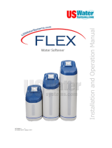
Model Tank Size A B C
FNLT-100 9” X 48” 54.375” 50.875” 9”
FNLT-150 10” X 54” 60.375” 57” 10”
FNLT-200 12” X 52” 58.625” 55.25” 12”
FNLT-250 13” X 54” 61.25” 57.625” 13”
FNLT-300 14” X 65” 72.25” 68.625” 14”
System Dimensions
Overall
System
Height
Inlet-Outlet
Connection
Height
C
Tank
Diameter
B A
17”
34.65
15”
34.65
FRONT
SIDE

7
Specifications
Continuous operation at flow rates greater than the service flow rate may affect capacity and efficiency performance.
The manufacturer reserves the right to make product improvements which may deviate from the specifications and
descriptions stated herein, without obligation to change previously manufactured products or to note the change.
The above capacity and flow rate specifications have not been validated by WQA.

8
Visit us online at www.USWaterSystems.com Give us a call at: 1-800-608-8792
The principle behind water softening is simple chemistry. A water softener contains resin
beads which hold electrically charged ions. When hard water passes through the softener,
calcium and magnesium ions are attracted to the charged resin beads. The result is remov-
al of calcium and magnesium ions which produces soft water.
This system is controlled with simple, user-friendly electronics displayed on a LCD screen.
The main page displays the current time and the remaining gallons in meter mode or the re-
maining days in calendar clock mode. The system will also scroll through other pertinent
information.
Place the softener as close as possible to
the pressure tank (well system) or water
meter (city water).
Place the softener as close as possible to
a floor drain, or other acceptable drain
point (laundry tub, sump, standpipe, etc.).
Connect the softener to the main water
supply pipe BEFORE the water heater.
DO NOT RUN HOT WATER THROUGH
THE SOFTENER. Temperature of water
passing through the softener must be less
than 100 deg. F.
Outside faucets and irrigation systems
should be supplied with hard water prior to
the water softener.
Do not install the softener in a place where
it could freeze. Damage caused by freez-
ing is not covered by the warranty.
Put the softener in a place water damage
is least likely to occur if a leak develops.
The manufacturer will not repair or pay for
water damage.
A 120 volt electric outlet is needed within 6
feet of the softener. The transformer has
an attached 6 foot power cable. Be sure
the electric outlet and transformer are
in an inside location, to protect from
wet weather.
If installing in an outside location, you must
take the steps necessary to assure the sof-
tener, installation plumbing, wiring, etc. are
protected from the elements and contami-
nation sources.
Keep the softener out of direct sunlight.
The sun’s heat may soften and distort
plastic parts.
How the Water Conditioner Works
Where To Install The Softener

9
Softener Preparation
Fusion NLT Tank Preparation
WATER PRESSURE: A minimum of 20 pounds of water pressure is required for re-
generation valve to operate effectively.
ELECTRICAL FACILITIES: An uninterrupted alternating current (A/C) supply is re-
quired. Note: Other voltages are available. Please make sure your voltage supply is com-
patible with your unit before installation.
EXISTING PLUMBING: Condition of existing plumbing should be free from lime and
iron buildup. Piping that is built up heavily with lime and/or iron should be replaced.
LOCATION OF FUSION NLT TANK AND DRAIN: The Fusion NLT tank should be lo-
cated close to a drain to prevent air breaks and back flow.
CAUTION: Water pressure is not to exceed 80 psi, water temperature is not to ex-
ceed 110°F (43°C), and the unit cannot be subjected to freezing conditions.
Resin Installation
1. Remove the tank from carton.
2. Verify the riser tube is centered in the bottom center of the tank. A flashlight may be
necessary. There is an indentation in the bottom of the tank that will center the
tube. The tube should be flush with the top of the tank when it is installed correctly.

10
Visit us online at www.USWaterSystems.com Give us a call at: 1-800-608-8792
3. Place a piece of duct tape over the riser tube so no media enters the riser while filling.
4. Use the Blue Funnel provided, to pour the media into the tank. Pour it evenly around
the hole to ensure it is well distributed in the tank and pour slow enough, to keep from
plugging the hole. A helper may be needed to hold the funnel during the filling pro-
cess. It is recommended that a dust mask and safety goggles be worn to prevent pos-
sible injury.
5. When media is installed move tank side to side to settle the media. Remove the fun-
nel and tape from the distributor tube.
Softener Preparation

11
Softener Preparation
6. Lubricate the distributor O-ring and the outer tank O-ring.
7. Install the upper basket on the bottom of the valve by lining up the tabs then turning
the basket clockwise to lock it in place. Place the upper basket over the distributor
tube and push the valve on the tank. Thread the valve on the tank by turning it clock-
wise. Be sure not to cross-thread the valve on the tank.
8. Tighten the valve hand tight, then snug it further by tapping it with the palm of the
hand. DO NOT use tools to tighten the valve or damage could occur.

12
Visit us online at www.USWaterSystems.com Give us a call at: 1-800-608-8792
Installation Instructions
1. If your hot water tank is electric, turn off the power to it to avoid damage to the element
in the tank.
2. If you have a private well, turn the power off to the pump and then shut off the main
water shut off valve. If you have municipal water, simply shut off the main valve. Go to
the faucet, (preferably on the lowest floor of the house) turn on the cold water until all
pressure is relieved and the flow of water stops.
3. Locate the softener tank and brine tank close to a drain where the system will be in-
stalled. The surface should be clean and level.
NOTE: ON COPPER PLUMBING SYSTEMS BE SURE TO INSTALL A GROUNDING
WIRE BETWEEN THE INLET AND OUTLET PIPING TO MAINTAIN GROUND-
ING.
Any solder joints being soldered near the valve must be done before connecting any piping
to the valve. Always leave at least 6" (152 mm) between the control valve and joints being
soldered when soldering pipes that are connected to the valve. Failure to do this could
cause damage to the valve.
The Fusion NLT is equipped with 1” removable connectors. It is recommended that these
connectors are installed in the plumbing fitting using Teflon tape then lubricate the o-ring on
the connector remove the red clips and push them into the bypass valve once they are tight
in the plumbing fitting. The red clips can then be re-installed to secure the connectors in the
bypass valve.
The inlet and outlet can be identified on the bypass valve. There are arrows stamped in the
bypass valve showing flow (See page 19 diagram). The arrow pointing toward the valve is
the inlet and the arrow pointing away from the valve is the outlet.
NOTE: All piping should be secured to prevent stress on the bypass valve and con-
nectors.

13
5. Connect the drain hose to the valve and secure it with a hose clamp. Run the drain
hose to the nearest laundry tub or floor drain. This can be ran up overhead or down
along the floor. Drain hose should be a minimum of 1/2”. If running the drain line more
than 20 ft overhead, it is recommended to increase the hose size to 3/4”. A DIRECT
CONNECTION INTO A WASTE DRAIN IS NOT RECOMMENDED. A PHYSICAL AIR
GAP OF AT LEAST 1.5” SHOULD BE USED TO AVOID BACTERIA AND
WASTEWATER TRAVELLING BACK THROUGH THE DRAIN LINE INTO THE SOF-
TENER.
NOTE: Be sure to secure the drain line. The softener will drain with force and it
should be secured to prevent a leak. Hose clamps should be used to se-
cure the drain line at the connection points.
Hose barb fitting for drain line.
Be sure to use a hose clamp to
secure the line.
Installation Instructions

14
Visit us online at www.USWaterSystems.com Give us a call at: 1-800-608-8792
6. Connect the brine line to the control valve by removing the nut on the brine elbow on
the control valve and sliding it on the brine line. There is a brass stiffener pre-installed in
the line.
Push the brine line in the elbow fitting on the control valve until it stops. Then push the nut
down on the fitting and tighten it hand tight. Use channel locks to tighten the nut an addi-
tional 1/2 turn.
Installation Instructions

15
Now connect the brine line to the brine tank safety float assembly. Remove the brine tank
lid and the brine well cap. There is a red clip on the cap that will be used to hold the brine
line in place. Remove it and the tape holding it and put it to the side. Then push the brine
line through the brine tank and brine well.
Push the brine line in brine safety valve. Make sure it is completely pushed in. Then install
the red locking clip around the brine fitting between the gray collar and the brine elbow.
Install the white cap on the tube.
Installation Instructions

16
Visit us online at www.USWaterSystems.com Give us a call at: 1-800-608-8792
Installation Instructions
7. Using the Allen Key (included), place the unit in the bypass position (See page 19 for by-
pass valve handle placement. Slowly turn on the main water supply. At the nearest cold
treated water tap nearby remove the faucet screen, open the faucet and let water run a few
minutes or until the system is free of any air or foreign material resulting from the plumbing
work.
8. Make sure there are no leaks in the plumbing system before proceeding. Close the water
tap when water runs clean.
9. Open the brine tank lid and add 5 gallons of water to the brine tank. Add a minimum of
80lbs of salt to the brine tank.
10. Proceed to start up instructions.
Note: The unit is not ready for service until you complete the start-up instructions.

17
Installation Overview

18
Visit us online at www.USWaterSystems.com Give us a call at: 1-800-608-8792
System Start-Up
Key Pad Configuration
Start-up Instructions
SETTINGS This function is to enter the basic set up
information required at the time of installa-
tion.
MANUAL
REGEN
This function is to initiate an immediate or
delayed manual regeneration.
DOWN / UP Increase or decrease the value of the set-
tings while in the programming mode.
DELAYED REGENERATION
Press and release the MANUAL REGEN.
Button to set a delayed regeneration that will
occur at the regeneration time. The main dis-
play page will show DELAYED REGEN ON.
To cancel press and release the MANUAL
REGEN. Button. The main display page will
show DELAYED REGEN OFF.
IMMEDIATE REGENERATION
To start an immediate regeneration (or step
valve through each position), press and hold
the MANUAL REGEN. Button for 3 seconds
(until beeps). The valve will start an immedi-
ate regeneration. Press any key to skip to
the next cycle.
Manual Regeneration (Step / Cycle Valve)
1. Plug the power transformer into an ap-
proved power source. Connect the power
cord to the valve.
2. When power is supplied to the control, the
screen will display service position param-
eters. If screen is locked, the screen will
display “PRESS SETTINGS 3S TO UN-
LOCK”. Follow the instructions and press
SETTINGS for 3 seconds to unlock. Press
and hold the “Manual” regen button. The
valve will display “Advancing to Brine”.
Once the valve stops moving the valve will
display “Brine” and will show a time value
that is counting down.
3. Manually step the valve past the BRINE
position to the BACKWASH position.
Press any key to skip the BRINE cycle and
move to the Backwash cycle..
4. Once in the BACKWASH cycle with a time
value counting down, open the inlet on the
bypass valve slowly and allow water to en-
ter the unit. Allow all air to escape from the
unit before turning the bypass fully open.
Then allow water to run to drain for 3-4
minutes or until all media fines are washed
out of the softener indicated by clear water
in the drain hose.
5. When the backwash cycle is complete, the
valve will advance to the RINSE position.
Continue to let the softener rinse. Check
the drain line flow. Allow the water to run
for the entire rinse cycle.
6. When the rinse cycle is complete, the
valve will advance to the REFILL position.
Check that the valve is filling water into the
brine tank. Allow the valve to refill for the
full amount of time as displayed on the
screen to insure a proper brine solution for
the next regeneration.
7. The valve will automatically advance to the
SERVICE position. Open the outlet valve
on the bypass, then open the nearest
treated water faucet and allow the water to
run until clear, close the tap and replace
the faucet screen.
8. Program unit.

19
Settings
Press SETINGS key (3 SECONDS / BEEP)
VALVE MODE
SOFTENER UF
TIME OF DAY
12:01 PM
YEAR
2012
MONTH
AUGUST
DAY
21
SET HARDNESS
20 GRAINS
SET PEOPLE
4
SALT SETTING
HIGH EFFICIENCY
STANDARD
IRON & MN
WATER TYPE
MUNICIPAL
WELL / OTHER
REGEN TIME
2:00 AM
NAME STAR
PLUMBING
PHONE TEL (552)
764-1234
PROGRAMMING
COMPLETE
CHANGE SETTINGS
To change settings press the
SETTINGS key for 3 seconds.
The first screen to be displayed
will be the TIME OF DAY. To ad-
just the HOUR values, use the
UP or DOWN key. To advance to
the MINUTE values, press the
SETTINGS key again. After ad-
justing each value using the UP
or DOWN keys, continue advanc-
ing to the next value or screen by
pressing the SETTINGS key.
TIME OF DAY, YEAR, MONTH,
DAY,
Time of day is for normal opera-
tion of system and the scheduling
of the regeneration time. The
date is used in a diagnostic func-
tion to track the last time the sys-
tem regenerated.
SET HARDNESS
This value is the maximum com-
pensated water hardness in
grains per gallon of the raw water
supply. It is used to calculate the
system capacity. If Ferrous Iron
is present add 4 gpg for every 1
ppm of Ferrous Iron.
SET PEOPLE
This value is the number of peo-
ple living in the home. It is used
to calculate the amount of water
needed for daily use and the re-
serve capacity of the system.
SALT SETTING
Choose HIGH EFFICIENCY to
minimize salt usage. Your sys-
tem will regenerate a little more
often but your salt usage can be
reduced by 20% compared to the
STANDARD setting.
Choose STANDARD when you
need to maximize your capacity
but still operate the system with
good efficiency.
Choose IRON & MN if you have
problem water containing these
minerals. The high salt setting
will be needed since these miner-
als are more difficult to clean out
of the resin bed. Note: A resin
cleaner will also need to periodi-
cally added to the brine tank to
insure proper operation.
WATER TYPE
This setting will determine if the
BACKWASH OVERIDE function
will be on or off. Select MUNICI-
PAL if the water source is clean
(<1NTU turbidity) and the system
will skip the back wash cycle
based on the setting in BACK-
WASH OVERIDE.
Select WELL / OTHER if any Iron
or Manganese is present or if the
water source is not clean (<
1NUT turbidity). The system will
back wash every time.
REGEN TIME
This setting determines the time
of day to perform a scheduled
regeneration.
NOTE: The factory setting for “WATER TYPE” is “WELL / OTHER”. Do not adjust this
setting until after start-up is complete. If the setting is changed to
“MUNICIPAL” before start-up, the back wash cycle will be skipped.
Programming Instructions

20
Visit us online at www.USWaterSystems.com Give us a call at: 1-800-608-8792
Operation During A Power Failure
Safety Float
In the event of a power failure, the valve will keep track of the time and day for 48 hours.
The programmed settings are stored in a non-volatile memory and will not be lost during a
power failure. If power fails while the unit is in regeneration, the valve will finish regenera-
tion from the point it is at once power is restored. If the valve misses a scheduled regenera-
tion due to a power failure, it will queue a regeneration at the next regeneration time once
power is restored.
Main Display
The brine tank is equipped with a safety float which prevents your brine tank from overfilling
as a result of a malfunction such as a power failure.
About The System
Diagnostic Display
PARAMETER DESCRIPTION
JULY/17/2012
8:30 PM
TOTAL 1,500 GAL
REMAIN 1,200 GAL
PEOPLE 2
RESERVE 150 GAL
EST. DAYS TO NEXT
REGEN 06 DAYS
LAST REGEN
9/24/12
TOTAL REGENS
10
TOTAL GALLONS
001590 GAL
OVER RUN TOTAL
0500 GAL
CURRENT 1.5 GPM
PEAK 6.5 GPM
DELAYED REGEN
OFF
REGEN TIME
2:00 AM
REFILL TIME
3:00 MIN
VALVE MODE
SOFTENER UF
TOTAL 4 DAYS
REMAIN 3 DAYS
Month, Day, Year, Time
The current calculated refill time. (Note: The refill time shown will be reduced by the pre-fill
%. i.e. If pre-fill % is 70%, then displayed refill time will be 70% of the full target.)
The current setting for regeneration time.
Number of people in the household and the calculated reserve capacity. When remaining
reaches reserve capacity a regeneration will be scheduled.
The number of days remaining before regeneration. This option is only in filter mode.
The total amount is the system capacity when fully regenerated. The remaining is the
capacity left in the system.
The estimated number of days until the next regeneration will occur.
The date of the last regeneration.
The total number of regenerations.
The total amount of gallons treated by the system.
The total amount of water that has exceeded the system capacity over the last 4
regenerations. When remaining goes to zero, the gallons used will be added to over run total.
The current flow rate and the peak flow rate since the last regeneration.
Advises whether a delayed regeneration has been scheduled manually or automatically.
The current setting of the valve mode.
The main display will pause on the Date and Time page for 5 seconds. Then it will continually scroll through all
of the system diagnostic display pages. To manually scroll through the diagnostics, press the down or up key.
To reset the TOTAL REGENS, TOTAL GALLONS OVER RUN TOTAL, or PEAK flow rates, press and hold the
MANUAL REGEN key until the value changes to zero.
/