Page is loading ...

ABB Substation Automation Products and Systems
1MRS750886-MUM
Issued: 07.06.99
Version: A/07.06.99
Checked:H.S.
Approved: S-M.H.
REU 513
Combined Overvoltage and
Undervoltage Relay
User’s Guide
Data subject to change without prior notice

e

1MRS750886-MUM 3
REU 513User’s Guide
ABB Substation Automation
Products and Systems
Contents
Introduction .................................................................................5
Safety information .......................................................................7
Operator’s instructions .................................................................8
1. Operation indicators ....................................................................8
2. Control push-button ...................................................................10
Technical reference manual .......................................................11
1. Instructions ................................................................................11
1.1.Application ..........................................................................11
1.2.Requirements .....................................................................12
1.3.Configuration ......................................................................12
2. Technical description ................................................................13
2.1.Functional description ........................................................13
2.1.1. Product functions ........................................................13
2.1.1.1.Schema of product functions ...............................13
2.1.1.2. Overvoltage, undervoltage and positive-phase-
sequence .............................................................13
2.1.1.3.Inputs ...................................................................14
2.1.1.4.Outputs ................................................................14
2.1.1.5.Circuit-breaker failure protection ..........................14
2.1.1.6.Disturbance recorder ...........................................14
2.1.1.7.Self-supervision ...................................................14
2.1.2. Configuration ..............................................................16
2.1.3. Protection ...................................................................17
2.1.3.1.Block diagram ......................................................17
2.1.3.2.Overvoltage unit ...................................................17
2.1.3.3.Undervoltage unit .................................................18
2.1.3.4.Positive-phase-sequence protection ....................19
2.1.3.5.Time/voltage characteristics ................................20
2.1.3.6.Settings ................................................................23
2.1.3.7.Technical data of protection functions .................32
2.1.4. Monitoring ...................................................................33
2.1.5. Disturbance recorder ..................................................34
2.1.5.1.Function ...............................................................34
2.1.5.2.Recorder data ......................................................34
2.1.5.3.Control and indication of recorder status .............34
2.1.5.4.Triggering .............................................................34
2.1.5.5.Settings and unloading ........................................35

ABB Substation Automation
Products and Systems
User’s GuideREU 513
4 1MRS750886-MUM
2.1.5.6.Event code .......................................................... 35
2.1.6. Recorded data ........................................................... 36
2.1.7. Serial communication ................................................. 37
2.1.7.1.Communication ports .......................................... 37
2.1.7.2.Event codes ........................................................ 37
2.1.7.3.Remote transfer data .......................................... 40
2.1.7.4.Relay parameterization ....................................... 49
2.2. Design description ............................................................. 49
2.2.1. Input / output connections .......................................... 49
2.2.2. Technical data ............................................................ 52
3. Check lists ................................................................................ 57
Service ......................................................................................... 60
1. General ..................................................................................... 60
2. Secondary testing ..................................................................... 61
2.1. Testing of the matching transformers ................................ 62
2.2. Testing of the overvoltage stages ......................................62
2.2.1. Low-set stage U> ....................................................... 63
2.2.2. High-set stage U>> .................................................... 63
2.3. Testing of the undervoltage stages ................................... 64
2.3.1. Low-set stage U< ....................................................... 64
2.3.2. High-set stage U<< .................................................... 65
2.4. Testing of the self-supervision system (IRF) ..................... 65
2.5. Testing of the binary input ................................................. 65
3. Spare parts ............................................................................... 66
Ordering information ................................................................. 67
References ............................................................................... 68
Index/Glossary ......................................................................... 69

1MRS750886-MUM 5
REU 513User’s Guide
ABB Substation Automation
Products and Systems
Introduction
About this manual
The purpose of this manual is to provide the user with thorough information on the
relay REU 513 and its applications. The manual consists of three parts, the first of
which, part A, instructs the user in controlling the relay functions. Part B is a more
detailed description of the features, operation and applications of the relay, whereas
part C concentrates on service.
Instructions for installation are found in separate “Installation Manual”.
The use of the relay
The three-phase voltage relay REU 513 is intended to be used for overvoltage and
undervoltage protection and supervision in distribution substations. It can also be
used for protection of generators, motors and transformers.
The relay features two over- and two undervoltage protection functions that evaluate
the fundamental wave of the three phase-to-phase voltages but can also be
programmed to evaluate single phase-to-phase voltage. One of the undervoltage
stages can alternatively be set to evaluate the positive-phase-sequence voltage.
The protection relay REU 513 is based on a microprocessor environment. A self-
supervision system monitors continuously the operation of the relay.
Local control of the protection relay is carried out with a portable computer
connected to the front connector.
Features
• Overvoltage and undervoltage protection
• Single- or three-phase operation
• High-set overvoltage stage with definite-time or inverse definite minimum time
(IDMT) characteristic
• Low-set overvoltage stage with definite-time or IDMT characteristic
• High-set undervoltage stage with definite-time or IDMT characteristic
• Low-set undervoltage stage with definite-time or IDMT characteristic
• Positive-phase-sequence protection
• Settable drop-off/pick-up ratio for low-set overvoltage and low-set undervoltage
stages
• Circuit-breaker failure protection unit (CBFP)
• Disturbance recorder
• All settings are modified with a personal computer
• Settings are stored into non-volatile memory and remain even in case of power
supply failure
• Two normally open power output contacts
• Two change-over type signal output contacts
• Output contact functions freely configurable for desired operation
• Three accurate voltage inputs
• Galvanically isolated binary input with a wide input voltage range

ABB Substation Automation
Products and Systems
User’s GuideREU 513
6 1MRS750886-MUM
• Optical PC-connector for two-way SPA-bus data communication
• Continuous self-supervision of hardware and software. At a permanent fault all
stages and outputs are blocked.
• Rated frequency user-selectable 50/60 Hz
• Nominal voltage user-selectable 100/110/115/120 V
Guarantee
Please inquire the guarantee of your nearest ABB representative.

1MRS750886-MUM 7
REU 513User’s Guide
ABB Substation Automation
Products and Systems
Safety information
Dangerous voltages can occur on the connectors, even though the auxiliary voltage
is disconnected.
National and local electrical safety regulations must always be followed.
The frame of the protection relay has to be carefully earthed.
Only a competent electrician is allowed to carry out the electrical installation.
!
!
!

ABB Substation Automation
Products and Systems
User’s GuideREU 513
8 1MRS750886-MUM
A Operator’s instructions
1. Operation indicators
The function of the relay can be monitored with the help of three indication LEDs
on the relay front panel.
Fig. 1.-1 Operation indicators
Green READY indicator
• Indicator off:
The auxiliary voltage is not available.
• Lit indicator:
The relay is in normal operation, i.e. the CPU operates, no internal faults have
occurred, and auxiliary voltage is available to the relay.
• Blinking indicator:
The internal self-supervision system has detected an internal relay fault (IRF).
The output contact of the self-supervision system operates.
C
STARTREADY TRIP
Network Partner
REU 513
Order No: REU513A 405-BAA
Software No: 1MRS118017
Serial No: ER 000001
Uaux = 110-240 Vac
Uaux = 48-220 Vdc
fn = 50/60 Hz
Un = 100-120 V
REU 513

1MRS750886-MUM 9
REU 513User’s Guide
ABB Substation Automation
Products and Systems
Yellow START indicator
• Indicator off:
Normal operation mode. No protection function has started.
• Lit indicator:
A protection function has started. The start indication can be selected to be
latching or non-latching with switches SGF3/1, 3, 5 and 7.
A non-latching type of indication is automatically switched off when the fault
disappears and the protection stage resets.
A latching type of indication remains lit although the fault disappears until
cleared by pressing the [C] button.
• Blinking indicator:
Started protection functions are blocked by an external binary input. The
blocking indication is non-latching, i.e. it disappears with the binary input signal.
The start LED goes on blinking as long as a protection function or stage of the
relay is blocked. The blocking indication disappears when the binary input signal
is removed or when the protection function in question is no longer started.
Should the function still be started when the binary input signal is removed, the
start indication will be activated.
If a protection function is blocked when other protection functions are started but
not blocked, the indicator remains blinking; blocking has a higher priority than
starting.
Red TRIP indicator
• Indicator off:
Normal operation mode. No protection function has tripped.
• Lit indicator:
A protection function has tripped. The trip indication can be selected to be
latching or non-latching with switches SGF3/2, 4, 6 and 8.
A non-latching type of indication goes automatically off when the fault
disappears and the protection stage resets.
A latching type of indication remains lit, although the fault disappears, until
cleared by pressing the [C] button or via serial communication. As long as the
protection function is active it is not possible to reset the trip indicator.
Further, the indicators may be reset via the binary input X2.1/17-18 by applying
control voltage to the input, provided that switches SGB1/1...3 are in position 1.
The basic protection relay functions do not depend on the state of the operation
indicators, reset or non-reset. The relay is permanently operative.

ABB Substation Automation
Products and Systems
User’s GuideREU 513
10 1MRS750886-MUM
2. Control push-button
The front panel of the relay contains one push-button for clearing operation
indicators and unlatching relays. Operation indicators must be cleared and the [C]
button released before the relays can be unlatched. The table below describes the use
of the push-button.
Table 1: Control push-button
Push-button Pressed 1 s Pressed 5 s
C Clear operation indicators Unlatch relays

1MRS750886-MUM 11
REU 513User’s Guide
ABB Substation Automation
Products and Systems
B Technical reference manual
1. Instructions
1.1. Application
The overvoltage and undervoltage relay REU 513 is a secondary relay that is
connected to the voltage transformers of an object to be protected. It is designed for
overvoltage and undervoltage protection and supervision in distribution substations.
Other application areas are overvoltage and undervoltage protection of generators,
motors and transformers.
The three-phase overvoltage and undervoltage stages continuously measure the
phase-to-phase voltages of the system. On detection of a fault the relay starts, trips
the circuit breaker, provides alarms, records fault data etc., in accordance with the
application and the configured relay functions.
Both the overvoltage and the undervoltage units include two protection stages: low-
set stages U> and U<, and high-set stages U>> and U<<. Each protection stage can
be given a definite-time or an inverse definite minimum time (IDMT) characteristic.
The start and operation of the high-set and low-set undervoltage stages can be
blocked when the measured voltages are under 0.2 x U
n
. Further, the operation of all
protection stages can be blocked separately by means of an external binary input
signal.
The high-set undervoltage stage can be set to operate either based on conventional
undervoltage measurement or on the calculated positive-phase-sequence voltage
U1s. Selecting the positive-phase-sequence operation automatically deselects the
conventional high-set undervoltage stage operation, and vice versa.
The operation of the stage U< can be blocked by the start of the stage U<<. The high-
set stages of the overvoltage and undervoltage units can be deselected from
operation separately.
The protection functions are independent of each other unless configured to be
dependent, and they have their own setting groups as well as data recording. The
over- and undervoltage functions use conventional voltage transformer
measurement.
Output contact matrix allows any start or trip signal from the protection stages to be
routed to the desired output contact.

ABB Substation Automation
Products and Systems
User’s GuideREU 513
12 1MRS750886-MUM
1.2. Requirements
When the protection relay is operating under conditions specified below (see also
“Technical data”), the relay is practically maintenance-free. The relay includes no
parts or components subject to abnormal physical or electrical wear under normal
operating conditions.
Environmental conditions
• Specified ambient service temperature range -10...+55 °C
• Temperature influence on the operating values of the relay
within the specified ambient service temperature range 0.1% / °C
• Transport and storage temperature range -40...+70 °C
1.3. Configuration
Setting and connection example
The appropriate configuration of the output contact matrix enables using the trip
signals from the over- and undervoltage stages for operating two different circuit
breakers. The start signals can be used for blocking co-operating protection relays,
for signalling and for initiating autoreclosing.
Figure 1.3.-1 represents the relay with the default configuration.
Fig. 1.3.-1 Connection diagram of the overvoltage and undervoltage relay
L1
L2
L3
ConD1_U_513
U
aux
I/O
1
2
3
SGB1
SGB1
SGB1
∼
∼
X
3
X
3
2
X
2
X
1
X
1
X
X
4
X
4
5 6
3 4
13 14 15
1 2
17 18
1 3 4 6 7 9
SGB1
SGB1
5
6
10 11 12
7 8 9
X2.1
X1.1
100 V
110 V
115 V
120 V
3U<
3U<<
SGB1
7
SGB1
8
X
4
X
4
X
3
X
3
2
X
2
X
1
X
1
X
+ -
3U>
3U>>
100 V
110 V
115 V
120 V
100 V
110 V
115 V
120 V
a
PO1PO2
IRF
BI
SO1SO2
IRF
TRIP
SGR1
SGR2
SGR3
SGR4
START
START
TRIP
START
START
TRIP
TRIP
SGR5
SGR6
SGR7
SGR8
A
n
N
PC
1MKC950001-1
REU 513
INDICATORS RESET
RELAYS & IND. RESET
MEMORIZED VALUES
RESET
Blocking of stage U>>
Blocking of stage U>
Blocking of stage U<<
Blocking of stage U<
x = Factory Default
Optical
PC-interface

1MRS750886-MUM 13
REU 513User’s Guide
ABB Substation Automation
Products and Systems
2. Technical description
2.1. Functional description
2.1.1. Product functions
2.1.1.1. Schema of product functions
Fig. 2.1.1.1.-1 Product functions
2.1.1.2. Overvoltage, undervoltage and positive-phase-sequence
Refer to sections:
• 2.1.3.2. Overvoltage unit
• 2.1.3.3. Undervoltage unit
• 2.1.3.4. Positive-phase-sequence protection
59
U12
U23
U31
PrFU5_3
47
27
59
27
DEFINITE- OR INVERSE-TIME OVERVOLTAGE
PROTECTION, LOW-SET STAGE
PO1
PO2
SO1
SO2
IRF
DEFINITE- OR INVERSE-TIME
UNDERVOLTAGE PROTECTION,
LOW-SET STAGE
DEFINITE- OR INVERSE-TIME
UNDERVOLTAGE PROTECTION,
HIGH-SET STAGE
SERIAL COMMUNICATION
REMOTE RESET, REMOTE SETTING CONTROL OR
BLOCKING INPUT FOR THE DIFFERENT PROTECTION
STAGES
62 BF
CIRCUIT-BREAKER FAILURE
PROTECTION
DEFINITE- OR INVERSE-TIME POSITIVE-
PHASE-SEQUENCE PROTECTION
DEFINITE- OR INVERSE-TIME OVERVOLTAGE
PROTECTION, HIGH-SET STAGE
OPTICAL
PC-INTERFACE
BINARY INPUT BI

ABB Substation Automation
Products and Systems
User’s GuideREU 513
14 1MRS750886-MUM
2.1.1.3. Inputs
The relay includes three energizing inputs and one external binary input controlled
by an external voltage. The function of the binary input is determined with selector
switches of the protection relay.
For more details of the inputs, refer to section 2.2.1. Input / output connections and
tables 9, 31 and 35.
2.1.1.4. Outputs
The relay is provided with two power outputs (PO1 and PO2) and two signal outputs
(SO1 and SO2). Switchgroups SGR1...8 are used for routing the start and trip signals
of any protection stage to the desired signal or power output.
2.1.1.5. Circuit-breaker failure protection
The relay features a circuit-breaker failure protection (CBFP) unit. The CBFP unit
generates a trip signal via output PO2 after the set operate time 0.10 s...1.00 s if the
fault has not been cleared by that time.
Normally, the CBFP unit controls the upstream circuit breaker. It can also be used
for tripping via redundant trip circuits of the same circuit breaker if the circuit
breaker is provided with two trip coils. The circuit-breaker failure protection unit is
activated with a switch of switchgroup SGF.
2.1.1.6. Disturbance recorder
The relay includes an internal disturbance recorder, which records momentary
measured values, external BI signal and states of the internal protection stages. The
disturbance recorder can be set to be triggered on operation of stages or on an
external BI signal, either on the falling or rising trigger edge.
2.1.1.7. Self-supervision
The relay is provided with an extensive self-supervision system that continuously
supervises the software and the electronics of the relay. It handles run-time fault
situations and informs the user about an existing fault.
When a fault is detected, the relay first tries to eliminate it by restarting. Only after
the fault is found to be permanent, the green READY indicator starts to blink and
the protection relay delivers a fault signal to the self-supervision output contact. The
self-supervision output contact that is normally picked up drops off and a fault code
can be read from the relay. This code is a number that identifies the fault type. The
fault code shall be recorded, and stated when service is ordered.
The fault codes are listed in the following table.

1MRS750886-MUM 15
REU 513User’s Guide
ABB Substation Automation
Products and Systems
Table 2: Fault codes
Fault
code
Type of fault
4 No response on output contact test, PO1
5 No response on output contact test, PO2
6 No response on output contact test, SO1
7 No response on output contact test, SO2
30 Faulty program memory (ROM)
50 Faulty work memory (RAM)
51 Parameter memory (EEPROM) faulty, block 1
52 Parameter memory (EEPROM) faulty, block 2
53 Parameter memory (EEPROM) faulty, blocks 1 and 2
54 Parameter memory (EEPROM) faulty, blocks 1 and 2 have different checksums
55 Parameter memory (RAM) faulty
56 Parameter memory (EEPROM) key faulty
59 Faulty work memory (RAM)
131 Reference voltage too low, 24V
139 Reference voltage too high, 24V
195 Reference voltage too low, +15V
203 Reference voltage too high, +15V
222 Reference voltage too low, -15V
223 Reference voltage too high, -15V
253 No interruptions from the A/D-converter

ABB Substation Automation
Products and Systems
User’s GuideREU 513
16 1MRS750886-MUM
2.1.2. Configuration
The figure below illustrates how the start, trip and binary input signals can be
configured so that the required protection functions are obtained.
Fig. 2.1.2.-1 Signal diagram of the overvoltage and undervoltage relay
A certain functionality can be achieved with the configuration of the start, trip and
binary input signals. The operation of the protection functions and indications can
be configured as well. The functionality is selected with the switches of
switchgroups SGF (Functions), SGB (Binary Input/Blockings) and SGR (Relays).
The functions of these switches are explained in detail in the corresponding SG_-
tables.
17 18
X2.1
13 14 15
10 11 12
7 8 9
3 45 6
SDiag_U5_3
I/O
3U>
3U>>
3U<
3U<<
4
5
U12
U23
U31
6
7
8
1
2
3
4
4
4
4
4
4
4
3
3
3
3
3
3
3
3
2
2
2
2
2
2
2
2
1
1
1
1
1
1
1
1
IRF
START
TRIP
START
TRIP
SGR5
SGR6
SGR7
SGR8
START
START
TRIP
TRIP
SGB1
SGB1
SGB1
SGB1
SGB1
SGB1
SGB1
SGR1
SGR2
SGR3
SGR4
SGF1...SGF4
PO1PO2SO1
IRF
SO2
BI
INDICATORS RESET
RELAYS RESET
MEMORIZED VALUES
RESET
Blocking of stage U<<
Blocking of stage U<
Blocking of stage U>>
Blocking of stage U>

1MRS750886-MUM 17
REU 513User’s Guide
ABB Substation Automation
Products and Systems
2.1.3. Protection
2.1.3.1. Block diagram
Fig. 2.1.3.1.-1 Block diagram of the combined overvoltage and undervoltage
relay REU 513
2.1.3.2. Overvoltage unit
When one or several of the measured voltages exceed the set start value of the low-
set stage U> and the preset start time of ~ 60 ms elapses, the overvoltage unit begins
delivering a start signal. Further, when the set operate time for the low-set stage at
definite-time operation or the calculated operate time at inverse-time operation
passes, the overvoltage unit operates.
In the same way as the low-set stage, the high-set stage U>> of the overvoltage unit
begins delivering a start signal after a preset ~ 50 ms start time when the set start
value is exceeded. When the set operate time for the high-set stage at definite-time
operation or the calculated operate time at inverse-time operation elapses, the
overvoltage unit operates.
SGR2/x
SGR1/x
SO2
1
1
SGR7/x
SGR8/x
SGR6/x
SGR5/x
U<<
t<<, k<<
U>
U>>
U<
U<<
t>
t>>
t<
t<<
1
4
60 ms
50 ms
SO1
2
3
SGF2/5
SGF2/2
SGB1/4
SGB1/6
BI
SGB1/5
SGB1/8
SGB1/1
SGB1/2
SGB1/3
SGR3/x
SGR4/x
U>>
t>>, k>>
50 ms
SGF2/6
SGF4/3...4
SGF2/7
t<, k<
PO2
SGF1/2
40/80 ms
SGF1/5
PO1
SGF1/1
1
SGB1/7
U
U
U
U>
t>, k>
SGF4/1...2
U<
80 ms
SGF4/5
SGF1/3
40/80 ms
40/80 ms
5 s
1
1
0.1 ... 1s
SGF1/4
5 s
40/80 ms
C
START
SGF3/1, 3, 5,7
TRIP
SGF3/2, 4, 6, 8
SGF2/4
&
&
U1s
BlockU5_3
RESET INDICATORS, LATCHED OUTPUT RELAYS AND REGISTERS
RESET INDICATORS AND LATCHED OUTPUT RELAYS
RESET INDICATORS
SETTINGS (Group 1 / Group 2)
12
23
31
0.20 Un
0.20 Un
C
C
SGF4/6
C

ABB Substation Automation
Products and Systems
User’s GuideREU 513
18 1MRS750886-MUM
The low-set and high-set stages of the overvoltage unit may be given a definite-time
or an inverse definite minimum time (IDMT) characteristic. When the IDMT
characteristic is chosen, two time/current curve groups called A and B are available.
The high-set stage can be deselected from operation by setting a bit in one of the
software switchgroups. The deselection of the protection stage is indicated by “999”
in communication via the SPA bus.
2.1.3.3. Undervoltage unit
When one or several of the measured voltages fall below the set start value of the
low-set stage U< and the preset start time of ~ 80 ms elapses, the undervoltage unit
begins delivering a start signal. Further, when the set operate time for the low-set
stage at definite-time operation or the calculated operate time at inverse-time
operation passes, the undervoltage unit operates.
When the conventional operation mode is selected for the high-set undervoltage
stage and one or all of the measured voltages, depending on the set operation criteria,
fall below the set start value of the high-set stage U<<, the undervoltage unit begins
delivering a start signal after a preset ~ 50 ms start time.
When the positive-phase-sequence protection mode is selected for the high-set
undervoltage stage, and the calculated positive-phase-sequence voltage U1s falls
below the set start value of the high-set stage U<<, the undervoltage unit begins
delivering a start signal after a preset ~ 50 ms start time. When the set operate time
at definite-time operation or the calculated operate time at inverse-time operation for
the high-set stage elapses, the undervoltage unit operates.
The low-set and high-set stages of the undervoltage unit may be given a definite-
time or an inverse definite minimum time (IDMT) characteristic. When the IDMT
characteristic is chosen, one time/current curve group called C is available.
Starting and operation of the low-set and high-set undervoltage stages can be
internally blocked when the measured value falls below 0.2 x U
n
. This function is
selected in one of the software switchgroups.
The high-set stage can be deselected from operation by setting a bit in one of the
software switchgroups. The deselection of the protection stage is indicated by “999”
in communication via the SPA bus.
The operation of stage U< can be blocked by the start of the stage U<<. The selection
is made with a switch in one of the software switchgroups.

1MRS750886-MUM 19
REU 513User’s Guide
ABB Substation Automation
Products and Systems
Fig. 2.1.3.3.-1 Operation of the undervoltage unit when the function of the high-
set and low-set undervoltage stages is internally blocked in case
the voltage falls below 0.2 x U
n
2.1.3.4. Positive-phase-sequence protection
Instead of the phase-to-phase voltage measurement the high-set undervoltage stage
can be set to be based on the positive-phase-sequence voltage. The relay calculates
the voltage on the basis of the two phase-to-phase voltages U
12
and U
23
.
The function based on the positive-phase-sequence voltage can be applied to
disconnecting a smaller power plant from the outside network. This may be
necessary in case a fault somewhere else in the network causes a condition, critical
for the power plant. An example of this kind of a fault is a short circuit either on the
transmission or distribution network level.
The situation may be critical for the power plant for different reasons. For example,
due to the relay operation caused by a fault situation, the power plant may be left to
feed an isolated network. In this case, there is a risk that the isolated network, in an
asynchronous state compared to the rest of the network, is reconnected to the
network, e.g. as a result of an autoreclosure. Another hazardous situation would be
that the power plant falls into an asynchronous state during the fault condition. Both
of these hazards may be prevented if the power plant is disconnected from the
network quickly enough by opening the connecting circuit breaker.
The benefit of the disconnecting relay assembly based on the positive-phase-
sequence voltage is that the voltage value during the network fault or after it
measures well the criticalness of the fault for a smaller power plant. When the
positive-phase-sequence voltage falls below the critical limit, the power plant has to
be disconnected from the network.
t
U/Un
t
t
U<<
Un
U<
Un
0.2 Un
x
U<
t<
U<<
t<<
t<
t<<
20PERC

ABB Substation Automation
Products and Systems
User’s GuideREU 513
20 1MRS750886-MUM
The voltage relay measuring the positive-phase-sequence voltage complements
other methods, based on frequency relay and overcurrent relay, for disconnecting a
smaller power plant.
The positive-phase-sequence function can also be used instead of the conventional
high-set three-phase undervoltage protection based on phase-to-phase voltages. For
example, this kind of undervoltage protection function can be used for disconnecting
motors in case of voltage interruption so that the motors are prevented from starting
simultaneously when the voltage becomes available again.
The relay has to be set to three-phase use, not to single-phase use, when the positive-
phase-sequence operation criteria is selected.
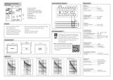
2.1.3.5. Time/voltage characteristics
At the IDMT characteristic, the operate time of the stage is a function of the voltage:
the greater the deviation from the setting value, the shorter the operate time. Three
time/voltage curve groups called A, B and C are available.
The overvoltage and undervoltage units can be given a definite-time or an inverse
definite minimum time operation characteristic. The settings of switches SGF4/1...2
determine the operation mode of stage U>, SGF4/3...4 that of stage U>>, switch
SGF4/5 determines the operation mode of stage U< and SGF4/6 that of stage U<<.
Refer to section “Settings” beginning from page 23.
Recording of the operate time does not start until the deviation between the
measured voltage and the setting value is 6 %. The operate time accuracy stated in
the technical data applies when the deviation is 10 % or greater.
Characteristics for overvoltage stages
The IDMT characteristic curve groups A and B are designed for overvoltage stages
U> and U>>. The stages U> and U>> can be configured to use different
characteristics. The relationship between time and voltage at inverse-time
characteristic can be expressed as follows:
where t = operate time [s]
k = time multiplier k> or k>>
U = measured voltage [V]
U> = set start voltage [V] for U> or U>>
a = constant 480
b = constant 32
c = constant 0.035
p = constant (see table 3)
The A- and B-type characteristics are illustrated in Fig. 2.1.3.5.-1 and Fig. 2.1.3.5.-2.
ts[]
ka×
b
UU>–
U>
------------------ 0.5–×
p
-------------------------------------------------- c+=
/