Page is loading ...

ABB Network Partner
User´s manual and
Technical description
SPAJ 141 C
Combined overcurrent
and earth-fault relay
U
RS 611 Ser.No.
f
n
= 50 / 60 Hz
n
=
n
=
SPAJ 141 C
aux
SPCJ 4D24
REGISTERS
OPER.IND.
0000
0
1
2
3
4
5
6
7
8
n
/
L3
n
/
L1
n
/
L2
max (15min)
on
1
2
3
4
5
6
7
8
>
START
>
TRIP
>
>
TRIP
>
>
START
>
o
START
>
>
o
START
>
o
TRIP
>
>
o
TRIP
2
5
9
%
)(
>
%
)(
>>
()
>
o
%
(
o
)
%
>>
CBFP
9
t
t
t
t
[]
[]
[]
[]
I
0084A
I
(
)
I
(
)
o
I
I
I
I
I
I
I
I
I
I
I
I
I
I
I
I
I
I
I
I
I
n
I
/
I
80...265V
~
–
18...80V
–
5A1A
1A0.2A
%
[]
SGR
SGB
SGF
SPCJ 4D24
TRIP
PROGRAM
RESET
STEP
L1 L2 L3 o
IRF
3>
I
I
I
II
I
>
n
I
I
/
k
s
>
t
[]
n
>
>
I
I
/
s
>
>
[]
t
s
o
>
[]
t
n
o
>
I
I
s
>
>
o
t
[]
n
>
>
o
II
0085A
%
[]
%
[
]

2
1MRS 750872-MUM EN
Issued 97-10-13
Version A (replaces 34 SPAJ 17 EN1)
Checked
Approved
Data subject to change without notice
Station
Automation
SPAJ 141 C
Combined overcurrent
and earth-fault relay
Contents Characteristics ................................................................................................................ 2
Application.....................................................................................................................2
Description of operation................................................................................................. 3
Connection diagram....................................................................................................... 4
Connections ................................................................................................................... 6
Control signals between the modules.............................................................................. 7
Signal abbreviations used................................................................................................ 7
Operation indicators....................................................................................................... 8
Power supply and output relay module........................................................................... 9
Technical data............................................................................................................... 10
Maintenance and repairs............................................................................................... 13
Spare parts .................................................................................................................... 13
Dimensions and instructions for mounting .................................................................. 14
Ordering information................................................................................................... 15
The complete manual for the relay SPAJ 141 C contains the following partial manuals:
General relay description 1MRS 750872-MUM EN
General characteristics of D-type relay modules 1MRS 750066-MUM EN
Combined overcurrent and earth-fault module SPCJ 4D24 1MRS 750121-MUM EN
Characteristics
Three-phase low-set overcurrent unit with defi-
nite time or inverse definite minimum time
(IDMT) characteristic.
Three-phase high-set overcurrent unit with in-
stantaneous or definite time function.
Low-set sensitive, non-directional earth-fault
protection with definite time characteristic.
High-set non-directional earth-fault protection
with instantaneous or definite time function.
Built-in breaker failure protection scheme.
Fully field-selectable output relay configuration.
Extensive data communication capabilities over
built-in serial port.
Outstanding design flexibility for easy selection
of appropriate operation schemes for various
applications.
Numerical display of setting values, current
measured values, memorized fault values etc.
Continuous self-supervision with auto-diagno-
sis of internal faults.
Application
The combined overcurrent and earth-fault relay
SPAJ 141 C is intended to be used for the selec-
tive short-circuit and earth-fault protection of
radial feeders in resistance earthed or impedance
earthed power systems. The integrated protec-
tive relay comprises both an overcurrent unit and
an earth-fault unit with highly flexible tripping
and signalling facilities. The feeder protection can
be used in applications requiring a single-, two-
or three-phase overcurrent protection and a non-
directional earth-fault protection. The overcur-
rent and earth-fault relay also comprises a circuit
breaker failure protection.

3
Description
of operation
The combined overcurrent and earth-fault relay
is a secondary relay device to be connected to
the current transformers of the feeder to be
protected. The three-phase overcurrent unit and
the non-directional earth-fault unit continu-
ously measure the phase currents and the neu-
tral current of the protected feeder. In fault situ-
ations these units initiate external auto-reclose
functions or trip the circuit-breaker, depending
on the selected protective scheme.
When a phase current exceeds the starting value
of the low-set overcurrent unit, the unit starts, si-
multaneously starting the corresponding timing
circuit. When the set operating time has elapsed,
a circuit-breaker tripping command is delivered.
Correspondingly, the high-set stage of the over-
current unit starts when its starting value is ex-
ceeded, starting its timing circuit and performing
a tripping when the set time has elapsed.
The low-set stage of the non-directional earth-
fault unit operates in the same way. Depending
on the protective scheme it either signals, per-
forms a tripping or initiates a function of an
external auto-reclose relay. The input circuit
comprises a low-pass filter, which reduces the
amount of harmonics in the neutral current
before the signal is measured.
The low-set stage of the overcurrent unit may be
given definite time or inverse definite minimum
time (IDMT) characteristics. When the IDMT
characteristic is to be chosen six curve types are
available in the relay. Four of the curves types
comply with BS 142 and IEC 255 and are named
normal inverse, very inverse, extremely inverse
and long-time inverse. The two additional curves
are named the RI curve and the RXIDG curve.
The low-set stage of the earth-fault unit is oper-
ating on a definite time basis.
By appropriate programming of the tripping
relay matrix, the starting signals of the overcur-
rent and non-directional earth-fault modules are
received as contact functions. This contact in-
formation is used e.g. for the blocking of co-
operating protective relays located upstreams.
The relay comprises one external logic control
input, which is actuated by a control signal of
the auxiliary voltage level. The influence on the
relay by the control input is determined by pro-
gramming switches in the measuring module.
The control input can be used either for block-
ing one or more of the protective stages, for re-
setting a latched output relay in the manual re-
set mode or for selecting a new group of relay
settings by remote control.
Fig. 1. Protective functions of the overcurrent and earth-fault relay SPAJ 141 C.
Three phase definite time or
dependent time low-set
overcurrent protection
Serial communication port
Trip
Signal 1
Serial I/O
IL1
IL2
IL3
Io
Blocking or
reset
Three phase instantaneous or
dependent time high-set
overcurrent protection
Instantaneous or definite time
high-set earth-fault protection
Remote reset, remote setting control or
blocking input for the different current stages
Signal 2
Start 1
IRF
Start 2
Circuit breaker failure protection
Definite time low-set
earth-fault protection
51
50
51 N
51BF
50 N

4
Connection
diagram
61
62
SPAJ 141 C
63
25
27
28
1
2
3
4
5
6
7
8
9
0.2 A
1 A
L1
L2
L3
70
71
72
0
65
66
U
+ (~)
- (~)
3I>
3I>>
Io>
Io>>
IRF
I/O
68
69
77
78
IRF
SIGNAL 2
-
+
TRIP
74
75
START 1
80
81
10
11
SGB/1
SGB/2
SGB/3
SGB/4
SGB/6
SGB/7
SGB/5
LATCHING
SIGNAL 1
START 2
RESET
I
-
I
0
+
+
+
B
+
C
+
F
+
E
+
D
+
A
U1
1
1
T2
T4
T6
T8
T1
T3
T5
T7
RC SETTINGS
SGB/8
SGF/4
0.1...1s
SGR2/8
SGR1/6
SGR1/8
SGR1/2
SGR1/4
U3
TRIP
R
U2
U1
T9
TS2
SS3
SS2
SS1
TS1
SPA-ZC_
Rx
Tx
SERIAL
PORT
+
-
1 A
5 A
1 A
5 A
1 A
5 A
SGR2/6
SGR2/4
SGR2/2
1
SGR2/7
SGR2/5
SGR2/3
SGR2/1
1
SGR1/7
SGR1/5
SGR1/3
SGR1/1
1
SGR3/8
SGR3/7
SGR3/6
SGR3/5
SGR3/4
SGR3/3
SGR3/2
SGR3/1
aux
~
EXTERNAL
CONTROL
Fig. 2. Connection diagram for the combined overcurrent and earth-fault relay SPAJ 141 C with
all the relay matrix switchgroups shown.

5
U
aux
Auxiliary voltage
A, B, C, D, E, F Output relays
IRF Self-supervision
SGR Switchgroups for the configuration of trippings and signallings
SGB Switchgroup for the configuration of the blocking or control signal
TRIP Trip output relay
SIGNAL 1 Signal on overcurrent trip
SIGNAL 2 Signal on earth-fault trip
START 1 Starting or auxiliary trip signal as selected with switchgroup SGR3
START 2 Starting of overcurrent low-set stage I>
U1 Three-phase overcurrent and non-directional earth-fault module SPCJ 4D24
U3 Input module SPTE 4E2
U2 Power supply and output relay module
SPTU 240 R1 or SPTU 48 R1
T1…T8 Starting and tripping indications
SERIAL PORT Serial communication interface
SPA-ZC_ Bus connection module
Rx/Tx Receiver bus terminal (Rx) and transmitter bus terminal (Tx) of the bus
connection module
Fig. 3. Rear view of relay SPAJ 141 C.
Made in Finland
= 63
68
69
77
78
80
81
1
2
3
4
5
6
7
8
9
25
27
28
61
62
63
65
66
74
75
70
71
72
10
11
Serial Port
SPA

6
Connections
The three phase-currents of the overcurrent pro-
tection are connected to terminals 1-2, 4-5 and
7-8, when the rated current of the secondary
circuits is I
n
= 5 A. When using current trans-
formers with a rated current of 1 A, terminals
1-3, 4-6 and 7-9 are used. The overcurrent pro-
tection may also be used in single-phase or two-
phase applications, in which case inputs not to
be used are left unconnected. In single-phase
applications, however, wiring the phase current
through two current inputs in series may in-
crease the operating speed of the relay, particu-
larly for instantaneous operations.
The neutral current of the earth-fault protec-
tion is connected to terminals 25-27 when the
rated current is 1 A and to terminals 25-28 when
the rated current is 0.2 A.
The control input 10-11 can be used in three
different ways, as the control input of an exter-
nal blocking signal for the measuring modules,
as the control input for unlatching the trip relay,
or as the control input for the remote control
of settings. The function is selected by means
of switches 1...8 of switchgroup SGB in the
main menu of the measuring relay module.
The auxiliary supply voltage of the relay is con-
nected to the terminals 61-62. At d.c. auxiliary
supply voltage the positive lead is connected to
terminal 61. The level of the voltage to be ap-
plied to the terminals is determined by the type
of power supply and output relay module in-
serted in the protection. For further details see
the description of the power supply module. The
auxiliary voltage range of the relay has been
marked on the front panel.
Output relay A provides the CB tripping com-
mands so that the CB operates once the operat-
ing time of the low-set or high-set stage of the
overcurrent or non-directional earth-fault mod-
ule has elapsed. The stages to perform a trip-
ping are selected with switches 2,4,6 and 8 of
switchgroup SGR1. On delivery from factory
all stages are selected to perform tripping. A
latching function of the output relay A can be
selected by means of switches SGB 6 and 7 for
overcurrent and earth-fault trippings.
The trip alarm signals from the measuring mod-
ules are obtained through output relays B and
C. The signals to be forwarded to the output
relays B and C are selected with switches1...8
of switchgroup SGR2 of the measuring mod-
ule. The switch matrixes for configuration of
the control signals of the output relays B and C
identical. Normally the output relays B and C
are given such a configuration that low-set and
high-set overcurrent trip alarm signal is obtained
over relay C and the corresponding alarm sig-
nal for the earth-fault trips via output relay B.
This is also the default setting on delivery.
The starting signals from the protective stages
of the relay are received through output relay
D. The signals to be forwarded to the output
relay D are selected by means of switches 1, 3, 5
and 7 of switchgroup SGR1 which is found in
the main menu of the measuring module. The
starting signals of the low-set and high-set stage
of the overcurrent unit are selected with switches
1 and 3, whereas switches 5 and 7 convey the
corresponding signals of the non-directional
earth-fault unit.
Output relay E, terminals 74-75, is a heavy duty
output relay capable of controlling a circuit
breaker, like the main trip relay A. Relay E is
used mainly for bringing out any starting or time
delayed signal for starting of auto-reclosures, for
signalling or counting purposes or for auxiliary
trip. Output relay E is also used as a tripping
output for the circuit breaker failure protection,
CBFP when the CBFP function is used. In this
case the trip signal can be used either to control
a circuit breaker upstreams or to control a sec-
ond trip coil on the main circuit breaker to give
a higher redundancy to the breaker operation.
Output relay F, terminals 70-71-72, operates as
the output relay of the self-supervision system
of the relay. The relay operates on the closed-
circuit principle so that in normal service con-
ditions the contact gap 70-72 is closed. If a fault
is detected by the self-supervision system, or if
there is a failure in the auxiliary supply, the out-
put relay drops off providing an alarm signal by
closing the NO contact 71-72.
The relay is interfaced with a data transmission
bus through a 9-pole, D-type subminiature con-
nector located at the rear panel of the relay. By
means of bus connection modules SPA-ZC 17
or SPA-ZC 21, the overcurrent and earth-fault
relay can be linked to the fibre-optic bus. The
terminals of the fibre-optic cables are connected
to the counter terminals Rx and Tx of the bus
connection module. The fibre-optic cables are
linked from one protection to another and to
the substation level communication unit, for
instance type SRIO 1000M.

7
Control signals
between the
modules
The figure below schematically illustrates how
the starting, tripping, control and blocking sig-
nals can be programmed to obtain the required
function of the protection.
SGR3 / 6
SGR1 / 8
IL1
IL2
IL3
SGR3 / 1
SGR1 / 1
SGR3 / 2
SGR2 / 1
SGR2 / 2
SGR1 / 2
SGR3 / 3
SGR1 / 3
SGR3 / 4
SGR2 / 3
SGR2 / 4
SGR1 / 4
SGR3 / 5
SGR1 / 5
SGR2 / 5
SGR2 / 6
SGR1 / 6
SGR3 / 7
SGR1 / 7
SGR3 / 8
SGR2 / 7
SGR2 / 8
I>
I>>
t>>
t>, k
to>
Io>
to>>
Io>>
Io
BS
SGB / 1
SGB / 2
SGB / 3
SGB / 4
SGB / 5
SGB / 8
REMOTE SETTINGS
RELAY RESET
1
SGB / 6
RESET+
PROGRAM
1
SGB / 7
RESET+
PROGRAM
1
1
1
SGF1 / 4
SS1
SS2
SPCJ 4D24
TS1
TS2
SS3
RESET
TRIP
0.1...1s
A
B
C
D
F
IRF
E
START 1
START 2
SIGNAL 1
SIGNAL 2
TRIP
IRF
(AR2)
(AR1)
(AR3)
SGF2 / 8
SGF2 / 7
SPTU ___R1
Fig. 4. Control signals between the modules of the overcurrent and earth-fault relay SPAJ 141 C.
The functions of the blocking and starting sig-
nals are selected with the switches of switch-
groups SGF, SGB and SGR. The checksums of
the switchgroups, are found in the setting menu
of the measuring relay module. The functions
of the different switches are explained in the
user´s manual of the measuring module SPCJ
4D24.
Signal
abbreviations
used
I
L1
, I
L2
, I
L3
Phase currents to be measured
I
0
Neutral current
BS Blocking or control Signal
SS1 Starting Signal 1
SS2 Starting Signal 2
SS3 Starting Signal 3
TS1 Tripping Signal 1
TS2 Tripping Signal 2
BS Blocking Signal
AR1...3 Auto-Reclose starting signals (not in use in SPAJ 141 C)
IRF Internal Relay Fault signal
SGF Switch Group for Functions
SGB Switch Group for Blockings
SGR Switch Group for Relay configuration
IRF Internal Relay Fault
Rx/Tx Receiver/Transmitter channel

8
Operation
indicators
A) The indicator TRIP is lit when one of the
protective stages operate. When the protective
stage resets, the red indicator remains lit.
B) If the display is dark when one of the pro-
tective stages I>, I>>, I
0
> or I
0
>> call for a trip-
ping, the faulty phase or the neutral path is in-
dicated with a yellow LED. If, for instance, the
TRIP indicator glows red, and the indicators
I
L1
and I
L2
at the same time are illuminated,
overcurrent has occurred on phase L1 and L2.
C) Besides being a code number at data presen-
tation, the leftmost red digit or the display serves
as a visual opetarion indicator. An operation in-
dicator is recognized by the fact that the red digit
alone is switched on. The following table named
OPERATION IND. on the relay front panel is
a key to the function code numbers used.
U
RS 611 Ser.No.
f
n
= 50 / 60 Hz
n
=
n
=
SPAJ 141 C
aux
SPCJ 4D24
REGISTERS
OPER.IND.
0000
0
1
2
3
4
5
6
7
8
n
/
L3
n
/
L1
n
/
L2
max
(15min)
on
1
2
3
4
5
6
7
8
>
START
>
TRIP
>
>
TRIP
>
>
START
>
o
START
>
>
o
START
>
o
TRIP
>
>
o
TRIP
2
5
9
%
)(
>
%
)(
>>
()
>
o
%
(
o
)
%
>>
CBFP
9
t
t
t
t
[]
[]
[]
[]
I
0084A
I
(
)
I
(
)
o
I
I
I
I
I
I
I
I
I
I
I
I
I
I
I
I
I
I
I
I
I
n
I
/
I
80...265V
~
–
18...80V
–
5A1A
1A0.2A
%
[]
SGR
SGB
SGF
SPCJ 4D24
TRIP
PROGRAM
RESET
STEP
L1 L2 L3
o
IRF
3>
I
I
I
II
I
>
n
I
I
/
k
s
>
t
[]
n
>
>
I
I
/
s
>
>
[]
t
s
o
>
[]
t
n
o
>
I
I
s
>
>
o
t
[]
n
>
>
o
II
0085A
%
[]
%
[
]
Indication Explanation
1 I> START = The low-set stage I> of the overcurrent unit has started
2 I> TRIP = The low-set stage I> of the overcurrent unit has tripped
3 I>> START = The high-set stage I>> of the overcurrent unit has started
4 I>> TRIP = The high-set stage I>> of the overcurrent unit has tripped
5I
0
> START = The low-set stage I
0
> of the earth-fault unit has started
6I
0
> TRIP = The low-set stage I
0
> of the earth-fault unit has tripped
7I
0
>> START = The high-set stage I
0
>> of the earth-fault unit has started
8I
0
>> TRIP = The high-set stage I
0
>> of the earth-fault unit has tripped
9 CBFP = Circuit Breaker Failure Protection has operated
D) The TRIP indications persist when the pro-
tective stage returns to normal. The indicator is
reset by pushing the RESET/STEP push-but-
ton.
Further, the indicators may be reset via the ex-
ternal control input 10-11 by applying a con-
trol voltage to the input, provided that the
switch SGB/8 is in position 1.
The basic protective relay functions are not de-
pending on the state of the operation indica-
tors, reset or non-reset. The relay is permanently
operative.
If a protective stage starts, but no tripping oc-
curs because the energizing quantity goes be-
low the starting level before the delay circuit
times out, the starting indicators are normally
automatically switched off. However, by means
of the switches SGF2/1…4 the starting indica-
tions may be made persistant which means that
they are to be reset by pushing the RESET/
STEP push-button.
The persistent indications are obtained through
the following programming.
Switch SGF2/1 = 1
Starting indication on I> persistent
Switch SGF2/2 = 1
Starting indication on I>> persistent
Switch SGF2/3 = 1
Starting indication on I
0
> persistent
Switch SGF2/4 = 1
Starting indication on I
0
>> persistent
On delivery from the factory the switches SGF2/
1…4 have the preset configuration 0.
E) Shortly after the internal self-supervision sys-
tem has detected a permanent relay fault the
red IRF indicator is switched on and the output
relay of the self-supervision system operates. Fur-
ther, in most fault situations a autodiagnostic
fault code is shown in the display. The fault code
is composed of a red figure 1 and a green code
number which indicates what may be the fault
type. The fault code persists until the STEP/
RESET button is pressed. When a fault code
appears on the display, the code number should
be recorded and stated when service is ordered.

9
Power supply
and output
relay module
To be able to operate the relay needs a secured
auxiliary voltage supply. The power supply mod-
ule forms the voltages required by the measur-
ing relay module and the auxiliary relays. The
withdrawable power supply and output relay
module is located behind the system front panel,
which is fixed by means of form cross-slotted
screws. The power supply and output relay
module contains the power supply unit, all out-
put relays, the control circuits of the output re-
lays and the electronic circuitry of the external
control inputs.
The power supply and output relay module can
be withdrawn after removing the system front
panel. The primary side of the power supply
module is protected with a fuse, F1, located on
the PCB of the module. The fuse size is 1 A
(slow).
The power supply unit is a transformer con-
nected, i.e. galvanically isolated primary and
secondary side, flyback-type dc/dc converter. It
forms the dc secondary voltages required by the
measuring relay module; that is +24 V, ±12 V
and +8 V. The output voltages ±12 V and +24 V
are stabilized in the power supply module, while
the +5 V logic voltage required by the measur-
ing relay module is formed by the stabilizer of
the relay module.
1 A slow
+8V
+12V
-12V
+24V
Uaux
80...265 V ac & dc
18...80 V dc
Unstabilized logics
voltage
Operation amplifier
voltage
Output relay coil
voltage
Fig. 5.Voltage levels of the power supply module.
A green LED indicator U
aux
on the system front
panel is illuminated when the power supply
module is in operation. The supervision of the
voltages supplying the electronics is placed in
the measuring module. If a secondary voltage
deviates from its rated value by more than 25 %,
a selfsupervision alarm will be established. An
alarm is also received when the power supply
module is withdrawn from the relay case, or
when the auxiliary power supply to the relay is
interrupted.
There are two versions of power supply and
output relay modules available. For both types,
the secondary sides and the relay configura-
tions are identical, but the input voltage ranges
differ.
Insulation test voltage between the primary and
secondary side and the protective earth
2 kV, 50 Hz, 1 min
Rated power P
n
5 W
Voltage ranges of the power supply modules:
- SPTU 240 R1 U
aux
= 80...265 V dc/ac
- SPTU 48 R1 U
aux
= 18...80 V dc
(on request )
The SPTU 240 R1 module can be used with both
ac and dc voltages. SPTU 48 R1 is designed for
dc supply only. The system front panel of the
relay indicates the auxiliary voltage range of the
power supply module of the relay assembly.

10
Technical data Energizing inputs
Rated current I
n
Overcurrent unit 1 A 5 A
Earth-fault unit 0.2 A 1 A
Thermal withstand capability
- continuously 2 A 4 A 20 A
- for 1 s 50 A 100 A 500 A
Dynamic current withstand, half-wave value 100 A 250 A 1250 A
Input impedance <750 mΩ <100 mΩ <20 mΩ
Rated frequency f
n
50 Hz
Rated frequency on request 60 Hz
Output contact ratings
Tripping contacts
Terminals 65-66, 74-75
- Rated voltage 250 V dc/ac
- Carry continuously 5 A
- Make and carry for 0.5 s 30 A
- Make and carry for 3.0 s 15 A
- Breaking capacity for dc, when the control circuit
time-constant L/R < 40 ms, at 48 / 110 / 220 V dc 5 A / 3 A / 1 A
Contact material AgCdO
2
Signalling contacts
Terminals
70-71-72, 68-69, 77-78, 80-81
- Rated voltage 250 V dc/ac
- Rated current 5 A
- Make and carry for 0.5 s 10 A
- Make and carry for 3.0 s 8 A
- Breaking capacity for dc, when the control circuit
time-constant L/R < 40 ms, at 48 / 110 / 220 V dc
control circuit voltage 1 A / 0.25 A / 0.15 A
Contact material AgCdO
2
External control inputs
Blocking, remote reset or remote setting input 10-11
External control voltage level 18...265 V dc or 80...265 V ac
Typical control current of input circuit 2…20 mA
Power supply and output relay module
Supply and relay module, type SPTU 240 R1 80...265 V dc/ac
Supply and relay module, type SPTU 48 R1 18...80 V dc (on request)
Power consumption under quiescent/
operating conditions 4 W/ 6 W

11
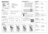
Overcurrent unit of SPCJ 4D24
Low-set overcurrent stage I>
Setting range 0.5...5.0 x I
n
Selectable modes of operation
- definite time operation
- operating time t> 0.05...300 s
- inverse definite minimum time (IDMT) mode
of operation as per IEC 255-4 and BS 142 Extremely inverse
Very inverse
Normal inverse
Long-time inverse
- special type inverse characteristics RI-type inverse
RXIDG-type inverse
- time multiplier k 0.05...1.0
High-set overcurrent stage I>>
Setting range 0.5...40 x I
n
and ∞
Operating time t>> 0.04...300 s
Note!
If the setting is higher than 2.5 x I
n
, the maximum continuous carry (4 x I
n
) and the levelling out
of the IDMT-curves at high current levels must be noted.
Note!
The high-current end of any inverse time characteristic is determined by the high-set stage which,
when started, inhibits the low-set stage operation. The trip time is thus equal to the set t>> for any
current higher than I>>. In order to get a trip signal, the stage I>> must also of course be linked to
a trip output relay.
Earth-fault unit of SPCJ 4D24
Low-set neutral overcurrent stage I
0
>
Setting range 1.0...25.0 % I
n
Selectable modes of operation
- definite time operation
- operating time t
0
> 0.05...300 s
High-set neutral overcurrent stage I
0
>>
Setting range 2...200 % I
n
and ∞
Operating time t
0
>> 0.05... 300 s
Data transmission
Transmission mode Fibre optic serial bus
Data code ASCII
Selectable data transfer rates 4800 or 9600 Bd
Fibre optic bus connection modules
with integral power unit
- for plastic core cables SPA-ZC 17 BB
- for glass fibre cables SPA-ZC 17 MM
Fibre optic bus connection modules
which are powered from the host relay
- for plastic core cables SPA-ZC 21 BB
- for glass fibre cables SPA-ZC 21 MM

12
Test voltages *)
Dielectric test voltage (IEC 255-5) 2 kV, 50 Hz, 1 min
Impulse test voltage (IEC 255-5) 5 kV, 1.2/50 µs, 0.5 J
Insulation resistance (IEC 255-5) >100 MΩ, 500 V dc
Disturbance tests *)
High-frequency (1 MHz) disturbance test
(IEC 255-22-1)
- common mode 2.5 kV
- differential mode 1.0 kV
Electrostatic discharge test (IEC 255-22-2
and IEC 801-2), class III
- air discharge 8 kV
- contact discharge 6 kV
Fast (5/50 ns) transients
- IEC 255-22-4, class III
- IEC 801-4, level IV:
power supply inputs 4 kV
other inputs 2 kV
Environmental conditions
Specified ambient service temperature range -10...+55°C
Long term damp heat withstand according
to IEC 68-2-3 < 95 % at 40°C for 56 d
Transport and storage temperature range -40...+70°C
Degree of protection by enclosure of the relay case
as per IEC 529 when panel mounted IP 54
Mass of the relay, when flush mounted 3.5 kg
*) The tests do not apply to the serial port, which is used for the bus connection module only.

13
Maintenance
and repair
When the protective relay is operating under
the conditions specified in the section "Techni-
cal data", the relay is practically maintenance-
free. The relay modules include no parts or com-
ponents subject to an abnormal physical or elec-
trical wear under normal operating conditions.
If the environmental conditions at the relay
operating site differ from those specified, as to
temperature, humidity, or if the atmosphere
around the relay contains chemically active gases
or dust, the relay ought to be visually inspected
in association with the relay secondary test or
whenever the relay modules are withdrawn from
the case. At the visual inspection the following
things should be noted:
- Signs of mechanical damage on relay modules,
contacts and relay case
- Accumulation of dust inside the relay cover
or case; remove by blowing air carefully
- Rust spots or signs of erugo on terminals, case
or inside the relay
On request, the relay can be given a special treat-
ment for the protection of the printed circuit
boards against stress on materials, caused by
abnormal environmental conditions.
If the relay fails in operation or if the operating
values remarkably differ from those of the relay
specifications, the relay should be given a proper
overhaul. Minor measures can be taken by per-
sonnel from the instrument work-shop of the
customer's company, e.g. replacement of auxil-
iary relay modules. All major measures involv-
ing overhaul of the electronics are to be taken
by the manufacturer. Please contact the manu-
facturer or his nearest representative for further
information about checking, overhaul and
recalibration of the relay.
Note!
Static protective relays are measuring instru-
ments and should be handled with care and pro-
tected against moisture and mechanical stress,
especially during transport.
Spare parts
Three-phase overcurrent and earth-fault module SPCJ 4D24
Power supply and output relay module
U
aux
= 80...265 V ac/dc SPTU 240 R1
U
aux
= 18...80 V dc SPTU 48 R1
Input module SPTE 4E2
Bus connection module SPA-ZC 17__ or SPA-ZC 21__

14
Dimensions for
mounting
The relay is housed in a normally flush-mounted
case. The relay can also be arranged for semi-
flush mounting with the use of a 40 mm, 80 mm
or 120 mm raising frame, which reduces the
depth behind the panel by the same dimension.
The type designations of the raising frames are
SPA-ZX 111 for the 40 mm frame, SPA-ZX 112
for the 80 mm frame and SPA-ZX 113 for the
120 mm frame. A surface mounting case SPA-
ZX 110 is also available.
The relay case is made of profile aluminium and
finished in beige.
A cast aluminium alloy mounting frame with a
rubber gasket provides a degree of protection
by enclosure to IP 54 between the relay case
and the panel surface when the relay is panel
mounted.
The relay case is complete with a hinged
gasketed, clear, UV-stabilized polycarbonate
cover with a sealable fastening screw. The de-
gree of protection by enclosure of the cover is
also IP 54.
A terminal strip and two multipole connectors
are mounted on the back of the relay case to
facilitate all input and output connections. To
each heavy duty terminal, i.e. measuring input,
power supply or trip output, one 6 mm
2
, one
4 mm
2
or one or two 2.5 mm
2
wires can be
connected. No terminal lugs are needed. The
signalling outputs are available on a six pole de-
tachable connector and the serial bus connec-
tion is using a 9-pin D-type connector.
Raising frame
SPA-ZX 111
SPA-ZX 112
SPA-ZX 113
176
136
96
74
114
154
ab
a
b
Panel cut-out
129 ±1
139 ±1
142
162
136
30
34
250
186
216

15
Ordering
information
When ordering, please, state:
Example
1. Type designation SPAJ 141 C
2. Rated frequency f
n
= 50 Hz
3. Auxiliary supply U
aux
= 110 V dc
4. Ordering number RS 611 007 - AA
5. Accessories
- Bus connection module SPA-ZC 21 BB
- Fibre-optic cable SPA-ZF AA5, 2 pces
- Fibre-optic cable SPA-ZF AA20, 5 pces
Ordering numbers for SPAJ 141 C
Type designation Name Order number
SPAJ 141 C Combined overcurrent and RS 611 007 - AA, -CA, -DA, -FA
earth-fault relay
SPAJ 141 C Combined overcurrent and RS 611 207 - AA, -CA, -DA, -FA
+ RTXP 18 earth-fault relay including a test
socket RTXP 18 mounted on
bars and prewired to the relay
The two last letters of the ordering number designate the rated frequency f
n
and
the range of the auxiliary voltage U
aux
of the relay as follows:
AA equals f
n
= 50 Hz and U
aux
= 80…265 V ac/dc
CA equals f
n
= 50 Hz and U
aux
= 18…80 V dc
DA equals f
n
= 60 Hz and U
aux
= 80…265 V ac/dc
FA equals f
n
= 60 Hz and U
aux
= 18…80 V dc

ABB Transmit Oy
Relays and Network Control
P.O.Box 699
FIN-65101 VAASA
Finland
Tel. +358 (0)10 22 4000
Fax. +358 (0)10 22 41094
1MRS 750872-MUM EN
Communications
Services
Meter & Load
Management
Information
Management
Network
Management
Station
Automation
Panorama is the standard for a comprehensive range
of integrated solutions for efficient and reliable
management of power networks. Using innovative
information technology, Panorama delivers total control
of the power process, from generation to consumption.
The Panorama standard covers six application areas,
each offering specific solutions.

User´s manual and
Technical description
General characteristics
of D type relay modules
SGR
SGB
SGF
SPCJ 4D29
TRIP
PROGRAM
RESET
STEP
L1 L2 L3
o
IRF
3>
I
I
II
I
>
n
I
I
/
k
s
>
t
[]
n
>
>
I
I
/
s
>
>
[]
t
s
o
>
k
o
[]
t
n
o
>
I
I
/
s
>
>
o
t
[]
n
>
>
o
I
/
I
879B
I
Relay symbol
Self-supervision alarm indicator
(Internal Relay Fault)
Display, 1 + 3 digits
Reset / Step push-button
Programming push-button
Trip indicator
Module type designation
Fastening screw
Indicators for measured quantities
Indicators for setting parameters
Indicators for switchgroups SGF, SGB
and SGR
Fastening screw
ABB Substation Automation Products and Systems

2
General characteristics
of D type relay modules
Contents
Front panel lay-out ......................................................................................................... 1
Control push buttons ..................................................................................................... 3
Display ........................................................................................................................... 3
Display main menu ................................................................................................... 3
Display submenus ..................................................................................................... 3
Selector switchgroups SGF, SGB, SGR .......................................................................... 4
Settings........................................................................................................................... 4
Setting mode ............................................................................................................. 4
Example 1: Setting of relay operation values.............................................................. 7
Example 2: Setting of relay switchgroups................................................................... 9
Recorded information................................................................................................... 11
Trip test function ......................................................................................................... 12
Example 3: Forced activation of outputs ................................................................. 13
Operation indicators..................................................................................................... 15
Fault codes.................................................................................................................... 15
1MRS 750066-MUM EN
Issued 95-04-12
Version A (replaces 34 SPC 3 EN1)
Checked JH
Approved TK
Data subject to change without notice

3
Control
push-buttons
The front panel of the relay module contains
two push buttons. The RESET / STEP push
button is used for resetting operation indicators
and for stepping forward or backward in the
display main menu or submenus. The PRO-
GRAM push button is used for moving from a
certain position in the main menu to the corre-
sponding submenu, for entering the setting
mode of a certain parameter and together with
the STEP push button for storing the set values.
The different operations are described in the
subsequent paragraphs in this manual.
Display
The measured and set values and the recorded
data are shown on the display of the protection
relay module. The display consists of four digits.
The three green digits to the right show the
measured, set or recorded value and the leftmost
red digit shows the code number of the register.
The measured or set value displayed is indicated
by the adjacent yellow LED indicator on the
front panel. When a recorded fault value is being
displayed the red digit shows the number of the
corresponding register. When the display func-
tions as an operation indicator the red digit
alone is shown.
When the auxiliary voltage of a protection relay
module is switched on the module initially tests
the display by stepping through all the segments
of the display for about 15 seconds. At first the
corresponding segments of all digits are lit one
by one clockwise, including the decimal points.
Then the center segment of each digit is lit one
by one. The complete sequence is carried out
twice. When the test is finished the display turns
dark. The testing can be interrupted by pressing
the STEP push button. The protection func-
tions of the relay module are alerted throughout
the testing.
Display main menu Any data required during normal operation are
accessible in the main menu i.e. present meas-
ured values, present setting values and recorded
parameter values.
The data to be shown in the main menu are
sequentially called up for display by means of
the STEP push button. When the STEP push
button is pressed for about one second, the
display moves forward in the display sequence.
When the push button is pressed for about 0.5
seconds, the display moves backward in the
display sequence.
From a dark display only forward movement is
possible. When the STEP push button is pushed
constantly, the display continuously moves for-
ward stopping for a while in the dark position.
Unless the display is switched off by stepping to
the dark point, it remains lit for about 5 minutes
from the moment the STEP push button was
last pushed. After the 5 minutes' time-out the
dispaly is switched off.
Display submenus Less important values and values not very often
set are displayed in the submenus. The number
of submenus varies with different relay module
types. The submenus are presented in the de-
scription of the concerned protection relay
module.
A submenu is entered from the main menu by
pressing the PROGRAM push button for about
one second. When the push button is released,
the red digit of the display starts flashing, indi-
cating that a submenu has been entered. Going
from one submenu to another or back to the
main menu follows the same principle as when
moving from the main menu display to another;
the display moves forward when the STEP push
button is pushed for one second and backward
when it is pushed for 0.5 seconds. The main
menu has been re-entered when the red display
turns dark.
When a submenu is entered from a main menu
of a measured or set value indicated by a LED
indicator, the indicator remains lit and the ad-
dress window of the display starts flashing. A
submenu position is indicated by a flashing red
address number alone on the dispaly without
any lit set value LED indicator on the front
panel.

4
Selector switch-
groups SGF, SGB
and SGR
Part of the settings and the selections of the
operation characteristic of the relay modules in
various applications are made with the selector
switchgroups SG_ . The switchgroups are soft-
ware based and thus not physically to be found
in the hardware of the relay module. The indi-
cator of the switchgroup is lit when the checksum
of the switchgroup is shown on the display.
Starting from the displayed checksum and by
entering the setting mode, the switches can be
set one by one as if they were real physical
switches. At the end of the setting procedure, a
checksum for the whole switchgroup is shown.
The checksum can be used for verifying that the
switches have been properly set. Fig. 2 shows an
example of a manual checksum calculation.
When the checksum calculated according to the
example equals the checksum indicated on the
display of the relay module, the switches in the
concerned switchgroup are properly set.
Switch No Pos. Weigth Value
11x1=1
20x2=0
31x4=4
41x8=8
51x16=16
60x32=0
71x64=64
8 0 x 128 = 0
Checksum ∑ =93
Fig. 2. Example of calculating the checksum of
a selector switchgroup SG_.
The functions of the selector switches of the
different protection relay modules are described
in detail in the manuals of the different relay
modules.
Settings
Most of the start values and operate times are set
by means of the display and the push buttons on
the front panel of the relay modules. Each
setting has its related indicator which is lit when
the concerned setting value is shown on the
display.
In addition to the main stack of setting values
most D type relay modules allow a second stack
of settings. Switching between the main settings
and the second settings can be done in three
different ways:
1) By command V150 over the serial communi-
cation bus
2) By an external control signal BS1, BS2 or
RRES (BS3)
3) Via the push-buttons of the relay module, see
submenu 4 of register A.
Setting mode Generally, when a large number of settings is to
be altered, e.g. during commissioning of relay
systems, it is recommended that the relay set-
tings are entered with the keyboard of a
personal computer provided with the necessary
software. When no computer nor software is
available or when only a few setting values need
to be altered the procedure described below is
used.
The registers of the main menu and the submenus
contain all parameters that can be set. The
settings are made in the so called setting mode,
which is accessible from the main menu or a
submenu by pressing the PROGRAM push
button, until the whole display starts flashing.
This position indicates the value of the param-
eter before it has been altered. By pressing the
PROGRAM push button the programming se-
quence moves forward one step. First the
rightmost digit starts flashing while the rest of
the display is steady. The flashing digit is set by
means of the STEP push button. The flashing
cursor is moved on from digit to digit by press-
ing the PROGRAM push button and in each
stop the setting is performed with the STEP
push button. After the parameter values have
been set, the decimal point is put in place. At the
end the position with the whole display flashing
is reached again and the data is ready to be
stored.
A set value is recorded in the memory by press-
ing the push buttons STEP and PROGRAM
simultaneously. Until the new value has been
recorded a return from the setting mode will
have no effect on the setting and the former
value will still be valid. Furthermore any attempt
to make a setting outside the permitted limits for a
particular parameter will cause the new value to be
disqualified and the former value will be main-
tained. Return from the setting mode to the
main menu or a submenu is possible by pressing
the PROGRAM push button until the green
digits on the display stop flashing.
/