Page is loading ...

SPAA 341 C /E351
Feeder Protection Relay
User´s manual and Technical description
RS 703 258 - AA Ser.No.
SPAA 341 C /E351
2
5
0036A
U
aux
18...80 V –
80...265 V
~
–
0
U1 U2 U3
0
SPCJ 4D28
0
SPCT 5D54
f
n
= 50Hz
60Hz
n
I
=
1A 5A
( )
I
n
I
=
( )
0B
I
1A 5A
n
U
=
( )
0
U
100V
n
I
=
( )
0
I
1A0,2A
120V
110V
1
2
3
4
5
6
7
8
A
OPERATION INDICATORS
Shot 1 due
Shot 2 due
CBFAIL
Final trip
Shot 5 due
Shot 4 due
Shot 3 due
t
d
t
r
CBFP
I
>
Start
I
0
>
Start
I
>
Trip
∆
1
2
3
4
5
6
7
8
9
0
11
A
I
0
>
Trip
I
>
Trip
>>
I
Start
>>
I
Trip
>
>>
I
Start
>
>>
I
Trip
>>
I
0
Start
>>
I
0
Trip
SPCJ 4D28 /E
CBFP
I
>
Start
I
0
>
Start
I
>
Trip
∆
1
2
3
4
5
6
7
8
9
0
11
A
I
0
>
Trip
I
>
Trip
>>
I
Start
>>
I
Trip
>
>>
I
Start
>
>>
I
Trip
>>
I
0
Start
>>
I
0
Trip
SGR
SGB
SGF
SPCJ 4D28
TRIP
PROGRAM
RESET
STEP
L1 L2 L3
o
IRF
3>
I
I
I
II
I
>
n
I
I
/
k
n
>
>
II
/
k
0
n0
>
I
I
/
0023A
n
I
/
I
>
>
>
>
>
t
[ ]
s
s
t
>
>
>
[ ]
s
0
>
t
[ ]
0
t
s
[ ]
n0
I
I
/
>
>
>
t
[ ]
s
>
t
[ ]
s
∆
>
I
∆
>
>
%
[ ]
SGR
SGB
SGF
SPCJ 4D28/E351
TRIP
PROGRAM
RESET
STEP
L1 L2 L3
o
IRF
3>
I
I
I
II
I
>
n
I
I
/
k
n
>
>
II
/
k
0
n0
>
I
I
/
0977A
n
I
/
I
>
>
>
>
>
t
[ ]
s
s
t
>
>
>
[ ]
s
0
>
t
[ ]
0
t
s
[ ]
n0
I
I
/
>
>
>
t
[ ]
s
>
t
[ ]
s
∆
>
I
∆
>
>
%
[ ]
SGR
SGB
SGF
SPCT 5D54
PROGRAM
RESET
STEP
IRF
AR1
DEF
TRIP
AR3AR2
O I
Shot 1
Shot 2
Shot 3
Shot 4
Shot 5
r
t
d
t
Final trip
0022A
AR4

2
SPAA 341 C /E351
Feeder Protection
Relay
Contents
Features .......................................................................................................................... 3
Application .....................................................................................................................3
Description of operation ................................................................................................. 4
Connections ................................................................................................................... 6
Specification of input and output terminals.................................................................... 8
Double-pole circuit breaker control ................................................................................ 9
Signal flow diagram ...................................................................................................... 10
Operation indicators ..................................................................................................... 11
I/O module .................................................................................................................. 11
Power supply module ................................................................................................... 12
Technical data .............................................................................................................. 12
Testing .........................................................................................................................15
Maintenance and repair ................................................................................................ 16
Spare parts .................................................................................................................... 16
Order numbers ............................................................................................................. 17
Dimensional drawings and mounting ........................................................................... 17
Ordering information ................................................................................................... 18
In addition to this general part the following descriptions of the individual modules
are included in the complete manual of the feeder terminal relay SPAA 341 C /E351:
Combined overcurrent and earth-fault relay module SPCJ 4D28 1MRS 750093-MUM EN
Combined overcurrent and earth-fault relay module SPCJ 4D28/E351 1MRS 751890-MUM EN
Auto-reclose relay module SPCT 5D54 1MRS 750095-MUM EN
General characteristics of D-type SPC relay modules 1MRS 750066-MUM EN
1MRS 751889-MUM EN
Issued 2000-07-20
Version A
Checked
Approved
Data subject to change without notice

3
Features
Three-phase overcurrent protection with three
stages
Two-stage non-directional earth-fault protec-
tion and phase discontinuity protection
Automatic reclosing allowing from one to five
auto-reclosures
Remote control of circuit breaker via auto-
reclose module
Five external control inputs enabling, for exam-
ple, external initiation of auto-reclosing
Seven freely configurable output relays and out-
put relays for self-supervision and circuit breaker
closing
Four trip contacts for double-pole CB opening
and double-pole CB closing
Recording of measured data which can be used
for analyzing the network condition
Transfer of data over serial communication bus
Continuous self-supervision and internal fault
diagnosis
Reading and writing of setting values via the
display and front panel push-buttons, a PC with
setting software or from higher systems levels
over the serial bus
Application
The feeder protection relay SPAA 341 C /E351
is designed to be used for selective short-circuit
and earth-fault protection of radial networks.
The integrated protection includes short-circuit
and earth-fault protection for one feeder, auto-
matic reclosing and signalling logic.

4
Description of
operation
The feeder protection relay SPAA 341 C /E351
is a secondary relay system to be connected to
the current transformers of the network section
to be protected. The feeder protection relay
includes three protection relay modules:
three-phase combined overcurrent and earth-
fault relay modules type SPCJ 4D28 and type
SPCJ 4D28/E351 and an auto-reclose relay
module type SPCT 5D54.
Combined over-
current and earth-
fault relay modules
SPCJ 4D28 and
SPCJ 4D28/E351
The overcurrent unit of the combined overcur-
rent and earth-fault relay module SPCJ 4D28
and SPCJ 4D28/E351 is intended to be used for
single-phase, two-phase or three-phase overcur-
rent protection. It includes three overcurrent
stages: I>, I>> and I>>>. An overcurrent stage
starts, as soon as the current on one of the phases
exceeds the setting value of the stage concerned.
Should the stage still be started when the operate
time selected for the stage elapses, it trips the
circuit breaker by delivering the configured trip
signal.
The earth-fault unit of the combined overcur-
rent and earth-fault relay module SPCJ 4D28
and SPCJ 4D28/E351 is intended to be used for
non-directional earth-fault protection. It in-
cludes two stages: a low-set stage I
0
> and a high-
set stage I
0
>>. When starting the stage provides
a start signal which can be programmed to
operate as the desired output signal. Should the
earth-fault persist when the operate time elapses,
the stage delivers a trip signal.
The low-set stages (I> and I
0
>) may have a
definite or an inverse time characteristic, whereas
the high-set stages operate according to the
definite time characteristic only. The operation
of the stages can be totally blocked by means of
the configuration switches.
The overcurrent and earth-fault relay module
SPCJ 4D28 and SPCJ 4D28/E351 also pro-
vides protection against phase discontinuity.
This phase discontinuity protection stage moni-
tors the minimum and maximum phase current
and calculates the differential current ∆I be-
tween the phases. The stage provides a trip
signal if the differential current is greater than
the setting value when the set operate time
elapses.

5
Auto-reclose relay
module SPCT 5D54
The auto-reclose relay module SPCT 5D54 is
capable of performing from one to five auto-
reclose shots and tripping the circuit breaker
finally. The auto-reclose shots are freely pro-
grammable to be initiated by short circuit, over-
current, earth fault or via an external control
input. When required, the initiation of an auto-
reclose sequence can be blocked by a short
circuit.
An auto-reclose shot can be initiated by start or
trip of the protection. When started by a start
signal of one of the protection modules, the
auto-reclose module opens the circuit breaker,
and when the dead time set for the concerned
AR shot elapses, it closes the circuit breaker.
Should the fault still persist when the auto-
reclosure has been carried out, the protection
relay module operates again initiating the next
shot until the whole AR sequence has been
completed. Then, if the fault proves permanent,
definite tripping will follow. Definite trip can be
carried out either by a protection relay module
or by the auto-reclose module (final trip func-
tion). At definite tripping the red DEF TRIP
indicator on the auto-reclose module is lit and
information about which of the protection func-
tions that initiated the unsuccessful AR se-
quence is available via the output signals.
The auto-reclose module is provided with a
maintenance monitor that records the opera-
tions of the circuit breaker. Each CB opening
decrements the value of the monitor according
to the stress factors. The alarm signal of the
maintenance monitor can be used to block auto-
reclose operations. The maintenance monitor
also allows a pre-alarm level to be set.
Different types of information, e.g., informa-
tion about auto-reclosure in progress, alarm on
definite tripping, and circuit breaker failure
alarm, can also be received as contact informa-
tion from the auto-reclose module.
The external control inputs of the auto-reclose
module can be used to initiate an auto-reclose
sequence, to prevent or interrupt an auto-reclos-
ure and to prevent CB closing.
Circuit-breaker
failure protection
The circuit-breaker failure protection integrated
into the relay modules SPCJ 4D28 and SPCJ
4D28/E351 enables a secured circuit breaker
trip system. The breaker fail function is linked
to the output relay TS1 so that in the event of the
local circuit breaker failing to trip, the trip signal
can be rerouted directly to the upstream circuit
breaker.

6
Connections
Fig. 1. Connection diagram for feeder protection relay SPAA 341 C /E351
SPAA 341 C /E351
1 A
5 A
1 A
5 A
L1
L2
L3
S1
S2
P1
P2
U1
(SPCJ 4D28)
AR
INH
U2
(SPCJ 4D28/E351)
U3
(SPCT 5D54)
BS1
BS2
1 A
CB
POS
BS 2 BS 1
CB POS
AR INH
1 A
5 A
BS1
BS2
BS1
BS2
U4
AR START
AR
CTRL
1 A
5 A
I
O
U
o
I
L3
I
L2
I
L1
I
OB
U
23
100/
110/
120 V
U
12
U
aux
+ (~)
- (~)
3I>
I
∆I>
RRES
RRES
0I
AR SYNC
C INH
RRES
+-
13 14 16 17 1 2 3 4 5 6 7 8 9 37 38 39 28 29 25 26 27 10 9 8 7 6 5 4 3 2 1 62 61X0X1X0 63
IRF
I/O
IRF
+
+
IRF
IRF
+
+
+
+
TS1
SS1
SS2
SS3
TS2
TS1
SS1
SS2
SS3
TS2
SS2
SS3
TS2
CBCS
TS3
SS4
I/O
TS3
SS4
I/O
TS3
SS4
-
0
-
I
I
0
++
-
TS1
SS1
SS1 TS1 SS2 TS2 SS3 TS3 SS4 CBCS
+++++
SPA-ZC_
Rx Tx
SERIAL
PORT
(SPA)
14 15 16 12 13 3 4 9 10 11 1 2 7 8 15 16 5 6 11 12 13 14X1X2X1X2X2X2X2X2X2
100/
110/
120 V
100/
110/
120 V
U5
~
0.2 A
3I>
I
∆I>

7
U
aux
Auxiliary voltage
TS1...TS3, CBCS Output relays (heavy-duty)
SS1...SS4 Output relays
IRF Self-supervision output relay
BS1, BS2 Control signals 1 and 2
CBPOS Circuit breaker status data
ARINH Signal for AR interruption and inhibition
ARCTRL Control signal for auto-reclosing
SS1...SS4
TS1...TS3, IRF Output signals
CBCS Signal for circuit breaker closing
U1 Combined overcurrent and earth-fault relay module SPCJ 4D28
U2 Combined overcurrent and earth-fault relay module SPCJ 4D28/E351
U3 Auto-reclose relay module SPCT 5D54
U4 I/O module
U5 Energizing input module
SERIAL PORT Serial communication port
SPA-ZC Bus connection module
Rx/Tx Fibre-optic cable connections
Made in Finland
= 63
1 2 3 4 5 6 7 8 9 10 11 12 13 14 15 16
16 15 14 13 12 11 10 9 8 7 6 5 4 3 2 1
X0
5
1
2
3
4
6
37
38
39
X2
X1
Serial Port
SPA
CBCSBS2 CBPOS ARINH ARCTRL TS3BS1
IRF SS1 SS2 SS3 SS4 TS1 TS2
7
8
9
14
61
62
63
13
16
25
26
27
17
28
29
I
L1
I
L2
I
L3
I
0B
U
aux
U
12
U
23
U
0
I
0
Fig. 2. Terminals of feeder protection relay SPAA 341 C /E351.

8
Specification of
input and output
terminals
Terminal Terminal interval Function
group
XO 1—2 Phase current I
L1
(5 A). Overcurrent protection
1—3 Phase current I
L1
(1 A). Overcurrent protection
4—5 Phase current I
L2
(5 A). Overcurrent protection
4—6 Phase current I
L2
(1 A). Overcurrent protection
7—8 Phase current I
L3
(5 A). Overcurrent protection
7—9 Phase current I
L3
(1 A). Overcurrent protection
13—14 Phase-to-phase voltage U
12
(100 V).
(Not used in SPAA 341 C /E351)
16—17 Phase-to-phase voltage U
23
(100 V).
(Not used in SPAA 341 C /E351)
37—38 Neutral current I
0B
(5 A). Earth-fault protection.
(SPCJ 4D28)
37—39 Neutral current I
0B
(1 A). Earth-fault protection.
(SPCJ 4D28)
25—26 Neutral current I
0
(1 A). Earth-fault protection.
(Not used in SPAA 341 C /E351)
25—27 Neutral current I
0
(0.2 A). Earth-fault protection.
(Not used in SPAA 341 C /E351)
28—29 Residual voltage U
0
(100 V). Earth-fault protection.
(Not used in SPAA 341 C /E351)
61—62 Auxiliary voltage supply. The positive pole of the DC supply
is connected to terminal 61. Auxiliary voltage range marked
on the front plate.
63 Protective earth
X1 1—2 External control signal BS1
3—4 External control signal BS2
5—6 Circuit breaker position input CBPOS. The input is energized
when the circuit breaker is open.
7—8 Auto-reclose inhibition signal ARINH
9—10 Auto-reclose control signal ARCTRL
11—12—13—14 Output relay CBCS
(heavy-duty, see "double-pole circuit breaker control")
15—16 Output relay TS3 (heavy-duty)
X2 1—2 Output relay TS2 (heavy-duty)
3—4 Output relay TS1 (heavy-duty)
5—6 Output relay SS4
7—8 Output relay SS3
9—10—11 Output relay SS2
12—13 Output relay SS1
14—15—16 Output relay IRF
The protection relay is connected to the fibre-
optic data bus via a bus connection module type
SPA-ZC 17 or SPA-ZC 21 that is fitted to the D
connector on the rear panel of the relay. The
optical fibres are connected to the counter con-
tacts Rx and Tx of the module. The selector
switches of the bus connection module are set to
the position "SPA".

9
Double-pole
circuit breaker
control
The circuit breaker closing can be implemented
as one-pole or double-pole connection. At dou-
ble-pole circuit breaker operation the control
voltage is applied to both sides of the circuit
breaker tripping coil: the negative and the posi-
tive polarity of the control circuit are separately
connected over the terminals 11—12 and 13—14
of the output relay CBCS.
Note!
When the CBCS relay is used with one-pole
connection the terminals 12 and 13 have to be
connected together.
Should double-pole circuit breaker opening be
required as well, two heavy-duty output relays
can be used for this purpose (e.g. TS2 and TS3).
+
+
+
+
+
-
0
-
I
SS1 TS1 SS2 TS2 SS3 TS3 SS4 CBCS
+++++
12 13 3 4 9 10 11 1 2 7 8 15 16 5 6 11 12 13 14X1X2X1X2X2X2X2X2
CLOSEOPEN
+
+
+
+
+
-
0
-
I
SS1 TS1 SS2 TS2 SS3 TS3 SS4 CBCS
+++++
12 13 3 4 9 10 11 1 2 7 8 15 16 5 6 11 12 13 14X1X2X1X2X2X2X2X2
OPEN OPEN CLOSE
a)
b)
Fig. 3. Principle of one-pole (a) and double-pole (b) operation.

10
Signal flow
diagram
Fig. 4 illustrates the internal signals of the feeder
protection relay and their configuration. The
numbers given in the small squares refer to the
configuration switches to be used to connect the
control signals to the required functions and
configure the start and trip signals to operate as
desired output signals or AR initiation signals.
Fig. 4. Internal signals of feeder protection relay SPAA 341 C /E351.
I> I>>
SPCJ 4D28
(U1)
IL1,IL2,IL3
IoB
Io
Uo
BS1
BS2
CBPOS
I>>> I
o
> I
o
>>
∆I>
∆t>
SS1 TS1 SS2 TS2 SS3 TS3 CBCSSS4
t>>>
SGF6
1
2 3 4 5 6
SGF7 1 2 3 4 5
6
SGF8
SGF8
1
2 3 4
5 6 7 8
SGR11
SGR9
SGR7
SGR5
SGR3
SGR1
SGR10
SGR8
SGR6
SGR4
SGR2
2
1
3
4
5
6
7
2
1
3
4
5
6
7
2
1
3
4
5
6
7
2
1
3
4
5
6
7
2
1
3
4
5
6
7
2
1
3
4
5
6
7
2
1
3
4
5
6
7
2
1
3
4
5
6
7
2
1
3
4
5
6
7
2
1
3
4
5
6
7
2
1
3
4
5
6
7
SGB1
1
2
3
4
6
SGB2
1
2
3
4
SGB3
1
2
3
4
AR2
AR1
AR3
SS1
TS1
SS2
TS2
SS3
TS3
SS4
SPCJ 4D28/E351
(U2)
SGR1
2
1
3
4
5
6
7
SGR2
2
1
3
4
5
6
7
SGR3
2
1
3
4
5
6
7
SGR4
2
1
3
4
5
6
7
SGR5
2
1
3
4
5
6
7
SGR6
2
1
3
4
5
6
7
SGR7
2
1
3
4
5
6
7
SGR8
2
1
3
4
5
6
7
SGR9
2
1
3
4
5
6
7
SGR10
2
1
3
4
5
6
7
SGR11
2
1
3
4
5
6
7
0 -> I
AR1
AR2
AR3
AR4
SGB1
1
2
3
SGB2
1
2
3
ARSYNC
CINH
CBPOS
ARINH
CBCS
Shot 1 due
CBOS
Def trip AR4
Def trip AR3
Def trip AR2
Def trip AR1
Shot 2 due
CBFAIL
Shot 5 due
Shot 4 due
Shot 3 due
13
12
X2
43
X2
11 10
X2
21
X2
87
X2
16 15
X1
65
X2
14 13
X1
12 119
SPCT 5D54
(U3)
RRES
SPAA 341 C /E351
t>
t>>
t
o
>
t
o
>>
I> I>>
I>>> I
o
> I
o
>>
∆I>
∆t>
t>>>
SGF6
1
2 3 4 5 6
SGF7 1 2 3 4 5
6
SGF8
SGF8
1
2 3 4
5 6 7 8
SGR11
SGR9
SGR7
SGR5
SGR3
SGR1
SGR10
SGR8
SGR6
SGR4
SGR2
2
1
3
4
5
6
7
2
1
3
4
5
6
7
2
1
3
4
5
6
7
2
1
3
4
5
6
7
2
1
3
4
5
6
7
2
1
3
4
5
6
7
2
1
3
4
5
6
7
2
1
3
4
5
6
7
2
1
3
4
5
6
7
2
1
3
4
5
6
7
2
1
3
4
5
6
7
SGB1
1
2
3
4
6
SGB2
1
2
3
4
SGB3
1
2
3
4
t>
t>>
t
o
>
t
o
>>
AR2
AR1
AR3

11
Operation
indicators
2. Measured values, settings and start and trip
data are indicated on the displays of the relay
modules. Starting and tripping are indicated
by the red operation code to the left of the
display. The operation codes are explained in
the manuals of the separate protection relay
modules and on the system panel of the
feeder protection relay.
The start indications can be programmed to
remain on even though the stage resets. Nor-
mally, the numbers indicating start are auto-
matically reset, whereas the trip codes have to
be reset by pressing the RESET push-button.
The TRIP indicator at the bottom part of the
front panel can be set to indicate starting and
tripping. The BS1, BS2 and RRES signals
can be configured to automatically reset the
trip indicators. The closing signal of the auto-
reclose relay module is linked to the RRES
input, which can be used to reset the opera-
tion indicators after a successful auto-reclose
sequence. An unreset operation indicator does
not affect the operation of the relay module.
3. Measured values and settings presented on
the display are identified by yellow LEDs on
the front panel.
4. A permanent fault detected by the self-super-
vision system is indicated by the IRF indica-
tor of the concerned relay module. The fault
code appearing on the display when a fault
occurs should be recorded to facilitate main-
tenance and repair.
The operation indicators are described in detail
in the manuals of the individual relay modules.
Fig. 5. Front panel of feeder protection relay
SPAA 341 C /E351.
1. The green LED U
aux
on the system panel is lit
when the power supply unit is operating.
I/O module
The I/O module of the feeder protection relay
SPAA 341 C /E351 is fitted in the rear part of
the relay, in the same direction as the mother PC
board. The module can be withdrawn after
undoing the fixing screws and disconnecting the
protective earth conductor of the cover and the
flat cable connected to the mother PC board.
The I/O module contains the output relays (8
pcs + IRF), the control circuits of the relays, the
electronic circuits for the five external control
inputs and the D connector required for serial
communications. The input and output signals
of the I/O module are linked to the mother
board over a flat cable. The relay module loca-
tions U1 and U2 are identical. The location U3
is intended for the auto-reclose module.
The output signals SS1...SS4, TS1...TS3 and
CBCS control an output relay with the same
designation. The operation of the stages are not
fixed to a particular output relay but can be
programmed for the desired output relays. It
should, however, be noted that the output relays
TS1, TS2, TS3 and CBCS can be used for
circuit breaker control. The configuration of the
switchgroups is described in detail in the relay
module manuals.
The operation of the external control inputs is
determined by the setting of the configuration
switchgroups of the relay modules. The control
inputs can be used for blocking one or several
protection stages, for resetting latched output
relays, selecting second settings, etc.
RS 703 258 - AA Ser.No.
SPAA 341 C
/E351
2
5
0036A
U
aux
18...80 V –
80...265 V
~
–
0
U1 U2 U3
0
SPCJ 4D28
0
SPCT 5D54
f
n
= 50Hz
60Hz
n
I
=
1A 5A
( )
I
n
I
=
( )
0B
I
1A 5A
n
U
=
( )
0
U
100V
n
I
=
( )
0
I
1A0,2A
120V
110V
1
2
3
4
5
6
7
8
A
OPERATION INDICATORS
Shot 1 due
Shot 2 due
CBFAIL
Final trip
Shot 5 due
Shot 4 due
Shot 3 due
t
d
t
r
CBFP
I
>
Start
I
0
>
Start
I
>
Trip
∆
1
2
3
4
5
6
7
8
9
0
11
A
I
0
>
Trip
I
>
Trip
>>
I
Start
>>
I
Trip
>
>>
I
Start
>
>>
I
Trip
>>
I
0
Start
>>
I
0
Trip
SPCJ 4D28 /E
CBFP
I
>
Start
I
0
>
Start
I
>
Trip
∆
1
2
3
4
5
6
7
8
9
0
11
A
I
0
>
Trip
I
>
Trip
>>
I
Start
>>
I
Trip
>
>>
I
Start
>
>>
I
Trip
>>
I
0
Start
>>
I
0
Trip

12
Power supply
module
The power supply module forms the voltages
required for the relay modules and the auxiliary
relay module. The power supply module is
located behind the system panel of the protec-
tion relay and can be withdrawn after removal of
the system panel.
The power supply module is available in two
versions as follows:
SPGU 240A1:
- rated voltage U
n
= 110/120/230/240 V ac
U
n
= 110/125/220 V dc
- operative range U = 80...265 V ac/dc
SPGU 48B2
- rated voltage U
n
= 24/48/60 V dc
- operative range U = 18...80 V dc
The voltage range of the power supply module
fitted in the relay is marked on the system panel
of the relay.
The power supply module is transformer con-
nected, i.e. the primary side and the secondary
circuits are galvanically isolated. The primary
side is protected by a fuse F1, located on the PC
board of the module. The fuse used in SPGU
240A1 is 1 A (slow) and that one used in SPGU
48B2 is 4 A (slow).
The green LED U
aux
on the front panel is lit
when the power supply module is in operation.
The supervision of the voltages supplying the
electronic circuits are integrated into the relay
modules. A self-supervision alarm is received, if
a secondary voltage deviates from its rated value
by more than 25%.
Technical data Energizing inputs
Rated current I
n
0.2 A 1 A 5 A
Terminal numbers X0/1-3,4-6 X0/1-2,4-5
X0/7-9,37-39 X0/7-8, 37-38
X0/25-27 X0/25-26
Thermal current withstand
- continuously 1.5 A 4 A 20 A
- for 10 s 5 A 25 A 100 A
- for 1 s 20 A 100 A 500 A
Dynamic current withstand
- half-wave value 50 A 250 A 1250 A
Input impedance <750 mΩ <100 mΩ <20 mΩ
Voltage inputs
Rated voltage U
n
, selectable 100 V (110 V/120 V)
Terminal numbers X0/13-14, 16-17, 28-29
Continuous voltage withstand 2 x U
n
Rated burden of voltage input at U
n
<0.5 VA
Output contacts
Trip contacts
Terminal numbers X1/15-16, 11-12-13-14
X2/1-2, 3-4
- rated voltage 250 V ac/dc
- continuous current carrying capacity 5 A
- make and carry for 0.5 s 30 A
- make and carry for 3 s 15 A
Breaking capacity for dc when the control
circuit time constant L/R ≤40 ms at the
control voltage levels
- 220 V dc 1 A
- 110 V dc 3 A
- 48 V dc 5 A
Contact material AgCdO
2

13
Signalling contacts
Terminal numbers X2/5-6, 7-8, 9-10-11
X2/12-13, 14-15-16
X2/1-2, 3-4
- rated voltage 250 V ac/dc
- continuous current carrying capacity 5 A
- make and carry for 0.5 s 10 A
- make and carry for 3 s 8 A
Breaking capacity for dc when the control
circuit time constant L/R ≤40 ms at the
control voltage levels
- 220 V dc 0.15 A
- 110 V dc 0.25 A
- 48 V dc 1 A
Contact material AgCdO
2
External control inputs
Blocking/control (BS1, BS2)
- terminal numbers X1/1-2, 3-4
Circuit breaker position data
- terminal number X1/5-6
Auto-reclose control
- terminal number X1/7-8, 9-10
External control voltage
- operative range 18...250 V dc or
80...250 V ac
Current drain of activated control input 2...20 mA
Auxiliary power supply
Voltage ranges of power supply modules:
SPGU 240A1:
- rated voltage U
n
= 110/120/230/240 V ac
U
n
= 110/125/220 V dc
- operative range U = 80...265 V ac/dc
SPGU 48B2
- rated voltage U
n
= 24/48/60 V dc
- operative range U = 18...80 V dc
Power consumption, under quiescent/
operation conditions 10 W/15 W
Combined overcurrent and earth-fault relay module SPCJ 4D28
- see "Technical data" in the manual for the module.
Combined overcurrent and earth-fault relay module SPCJ 4D28/E351
- see "Technical data" in the manual for the module.
Auto-reclose module SPCT 5D54
- see "Technical data" in the manual for the module.

14
Data communication
Transmission mode Fibre-optic serial bus
Coding ASCII
Data transfer rate, selectable 4800 Bd or 9600 Bd
Electrical/optical bus connection module
powered from the host relay
- for plastic core cables SPA-ZC 21BB
- for glass fibre cables SPA-ZC 21 MM
Electrical/optical bus connection module
powered from the host relay or from an
external power source
- for plastic core cables SPA-ZC 17BB
- for glass fibre cables SPA-ZC 17 MM
Test voltages *)
Dielectric test voltage (IEC 255-5) 2 kV, 50 Hz, 1 min
Impulse test voltage (IEC 255-5) 5 kV, 1.2/50 µs, 0.5 J
Insulation resistance (IEC 255-5) >100 MΩ, 500 V dc
Disturbance tests *)
High-frequency (1 MHz) disturbance test
(IEC 255-22-1)
- common mode 2.5 kV
- differential mode 1.0 kV
Electrostatic discharge test (IEC 255-22-2
and IEC 801-2), class III
- air discharge 8 kV
- contact discharge 6 kV
Fast (5/50 ns) transients
- IEC 255-22-4, class III
- IEC 801-4, level IV
- power supply inputs 4 kV
- other inputs 2 kV
Mechanical environmental test
Vibration test (IEC 255-21-1) class 1
Chock/bump test (IEC 255-21-2) class 1
Environmental conditions
Service temperature range -10...+55°C
Transport and storage temperature range
(IEC 68-2-8) -40...+70°C
Temperature influence 0.2%/°C
Damp heat test (IEC 68-2-30) 93...95%, +55°C, 6 cycles
Degree of protection by enclosure of
flush mounting relay case (IEC 529) IP 54
Weight of fully equipped relay 6 kg
*) The insulation and disturbance tests do not apply to the serial port, which is used for the bus
connection module only.

15
Testing
The relay should be subject to regular tests in
accordance with national regulations and in-
structions. The manufacturer recommends an
interval of five years between the tests.
The test should be carried out as a primary test,
which includes the whole protection arrange-
ment from the instrument transformers to the
circuit breakers.
The test can also be carried out as a secondary
injection test. Then the relay has to be discon-
nected during the test procedure. However, it is
recommended to check the condition of the
signal and trip circuits as well.
Note!
Make sure that the secondary circuits of the
current transformers under no condition open
or are open, when the relay is disconnected and
during the test procedure.
The test is recommended to be carried out using
the normal setting values of the relay and the
energizing inputs used. When required, the test
can be extended to include more setting values.
As the settings of the relay modules vary in
different applications, these instructions present
the general features of the test procedure. Ordi-
nary current and voltage supply units and in-
struments for measuring current, voltage and
time can be used for the tests.
During the test procedure the relay records
currents, voltages and relay operations. If the
recorded data are used for the collection of
information for longer time periods (for exam-
ple, AR counters), these registers should be read
before the test procedure is started. After the test
the registers are reset and, if required, the read-
ings of the AR counters can be restored.
The relay settings may have to be changed
during testing. A PC program is recommended
to be used to read the relay settings before
starting the test to make sure that the original
settings are being restored when the test has
been completed.
The protection stages used (I>, I>>, I>>>, I
0
>,
I
0
>> and ∆I>) are tested as follows:
- start value (the high-set stages for all three
phases)
- start time
- trip time
- trip indication, output relay operation and
signalling
- circuit breaker failure protection (CBFP)
Testing of over-
current and earth
fault relay modules
SPCJ 4D28 and
SPCJ 4D28/E351
General
Test the start value by gradually raising the
current, starting from zero, until the relay starts.
Record the current value required for starting.
The value should be within the permitted toler-
ances.
If the resetting value is to be tested as well, start
by raising the current until the relay starts and
then reduce the current until the relay resets.
When multi-stage protection relays are tested
the operation of the low-set stages may be a
problem when the high-set stages are tested.
Then it is often necessary to block or delay the
operation of the low-set stages, to be able to test
the operation of a high-set stage. In such a case
it is recommended to start from the highest stage
and then proceed to the lower stages. The ad-
vantage of this method is that the original set-
tings of the stages really are restored, because
otherwise the test cannot be carried out success-
fully.
Start value
Switch a current 2...2.5 times the setting value
of the protection stage to the relay. Measure the
operate time, i.e. the time from the closing of the
switch until the relay operates. The operate time
should be within the permitted tolerances, ex-
cept when the injected current is below 2 times
the setting value. In such a case the protective
algorithm adds about 20 ms to the operate
times.
When inverse times are measured the measure-
ment can be made with different supply cur-
rents, for example, 2 times and 10 times the
setting value, if required. The resetting time can
be measured from opening of the current switch
until resetting of the relay.
Start and trip times

16
Testing of the auto-reclose relay module in-
cludes:
- initiation of auto-reclosure
- output relay operation
- timers
- alarm indication
Testing of auto-
reclose relay module
SPCT 5D54
The operation of the auto-reclose module is
recommended to be tested together with the
overcurrent and earth-fault relay modules. Al-
ways when an overcurrent stage or an earth-fault
stage has been tested, the operation of the same
stage should be tested with the auto-reclose
module. The most convenient way is to use a
circuit breaker for the testing and then connect
the current to be applied to the relay over the
contact of the circuit breaker. The test can also
be carried out without using the circuit breaker.
Then the required configuration is selected in
the auto-reclose relay module (SGF2/7=1).
Start the test by closing the circuit breaker and
wait for the possible reclaim time to elapse.
Connect the energizing current/voltage and al-
low the relay to run the entire AR sequence.
Depending on the configuration the sequence
may include one or several AR shots and ends in
definite tripping performed by a protection
relay module or the auto-reclose module (final
trip function).
During the auto-reclose sequence no actions
that could interrupt the sequence or cause an
alarm signal are allowed. Depending on the
configurations definite tripping will provide an
alarm signal (DEFTRIP).
Testing of auto-reclose
sequence
Maintenance and
repairs
When the feeder protection relay is used under
the conditions specified in "Technical data", the
relay requires practically no maintenance. The
feeder protection includes no parts or compo-
nents that are sensitive to physical or electrical
wear under normal operating conditions.
Should the temperature and humidity at the
operating site differ from the values specified, or
the atmosphere contain chemically active gases
or dust, the relay should be visually inspected in
association with the secondary testing of the
relay. This visual inspection should focus on:
- Signs of mechanical damage to relay case and
terminals
- Collection of dust inside the relay case; remove
with compressed air
- Signs of corrosion on terminals, case or inside
the relay
If the relay malfunctions or the operating values
differ from those specified, the relay should be
overhauled. Minor measures can be taken by
the customer but any major repair involving the
electronics has to be carried out by the manufac-
turer. Please contact the manufacturer or his
nearest representative for further information
about checking, overhaul and recalibration of
the relay.
The protection relay contains circuits sensitive
to electrostatic discharge. If you have to with-
draw a relay module, ensure that you are at the
same potential as the module, for instance, by
touching the case.
Note!
Protective relays are measuring instruments and
should be handled with care and protected
against moisture and mechanical stress, espe-
cially during transport.
Spare parts
Combined overcurrent and earth-fault relay module SPCJ 4D28
Combined overcurrent and earth-fault relay module SPCJ 4D28/E351
Auto-reclose relay module SPCT 5D54
Power supply modules
- U = 80...265 V ac/dc (operative range) SPGU 240A1
- U = 18...80 V dc (operative range) SPGU 48B2
I/O module SPTR 9B25
Case (including connection module) SPTK 8B17
Bus connection module SPA-ZC 17_
SPA-ZC 21_

17
Order numbers
Feeder protection relay SPAA 341 C /E351 without test adapter:
RS 703 258-AA/E351
Feeder protection relay SPAA 341 C /E351 with test adapter RTXP 18:
RS 703 458-AA/E351
The letter combinations of the order number denote the rated frequency f
n
and
auxiliary voltage U
aux
of the protection relay:
AA: f
n
= 50 Hz and U
aux
= 80...265 V ac/dc
Dimension
drawings and
mounting
The basic model of the protection relay case is
designed for flush-mounting. When required,
the mounting depth of the case can be reduced
by using raising frames: type SPA-ZX 301 re-
duces the depth by 40 mm, type SPA-ZX 302
by 80 mm and type SPA-ZX 303 by 120 mm.
When projecting mounting is preferred a relay
case type SPA-ZX 317 is used. The relay case for
projecting mounting is provided with front
connectors.
Raising frame
SPA-ZX 301
SPA-ZX 302
SPA-ZX 303
219
179
139
74
114
154
ab
226
162
136
229
293
259
30
34
a
b
Panel cut-out
214 ±1
139 ±1
Fig. 15. Dimension and mounting drawings for feeder protection relay SPAA 341 C /E351.

18
The relay case is made of profile aluminium and
finished in beige.
The rubber gasket fitted to the mounting collar
provides an IP 54 degree of protection by enclo-
sure between the relay case and the mounting
base.
The hinged cover of the case is made of transpar-
ent, UV-stabilized polycarbonate polymer and
provided with two sealable locking screws. The
rubber gasket of the cover provides an IP 54
degree of protection between the case and the
cover.
The required input and output connections are
made to the screw terminals on the rear panel.
Terminal block X0 consists of screw terminals
fitted to the rear panel of the relay. The terminal
blocks X1 and X2 are provided with discon-
nectable multi-pole screw terminals. The male
parts of the disconnectable terminal blocks are
attached to the I/O module. The female parts
are included in the delivery. The female part can
be locked to the male part with fixing accessories
and screws.
Measured data, auxiliary voltage and protective
earth are wired to the terminal block X0. Each
terminal screw is dimensioned for one wire of
maximum 6 mm
2
or two wires of maximum 2.5
mm
2
.
Binary input and output signals are connected
to the multi-pole terminal blocks X1 and X2.
Each screw terminal is dimensioned for one wire
of maximum 1.5 mm
2
or two wires of maxi-
mum 0.75 mm
2
.
The 9-pole D-type connector is intended for
serial communication.
The bus connection modules (SPA-ZC 17, -21
or -22) and fibre-optic cables recommended by
the manufacturer should always be used for
serial communication.
Order data
Example
1. Number and type designation 10 SPAA 341 C /E351 units
2. Order number RS 703 258 -AA/E351
3. Rated frequency f
n
= 50 Hz
4. Auxiliary voltage U
aux
= 110 V dc
5. Accessories 10 bus connection modules SPA-ZC 17 MM2A
6. Special requirements -

SGR
SGB
SGF
SPCJ 4D28
TRIP
PROGRAM
RESET
STEP
L1 L2 L3
o
IRF
3>
I
I
I
II
I
>
n
I
I
/
k
n
>
>
II
/
k
0
n0
>
I
I
/
0023A
n
I
/
I
>
>
>
>
>
t
[ ]
s
s
t
>
>
>
[ ]
s
0
>
t
[ ]
0
t
s
[ ]
n0
I
I
/
>
>
>
t
[ ]
s
>
t
[ ]
s
∆
>
I
∆
>
>
%
[ ]
SPCJ 4D28
Overcurrent and earth-fault relay module
User´s manual and Technical description

2
SPCJ 4D28
Overcurrent and earth-fault
relay module
Contents
Characteristics ................................................................................................................ 2
Description of function .................................................................................................. 3
Overcurrent unit ....................................................................................................... 3
Earth-fault unit.......................................................................................................... 3
Filter characteristics of the measuring inputa ............................................................. 4
Phase discontinuity unit ............................................................................................ 4
Circuit breaker failure protection unit ....................................................................... 4
Output signals ........................................................................................................... 4
Auto-reclose start initiation signals ............................................................................ 5
Second settings .......................................................................................................... 5
Resetting ................................................................................................................... 5
Block diagram................................................................................................................. 6
Front panel .....................................................................................................................7
Operation indicators ....................................................................................................... 8
Settings (modified 99-10) ................................................................................................ 9
Measured data .............................................................................................................. 16
Recorded information................................................................................................... 17
Menu chart ................................................................................................................... 20
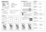
Time/current characteristic curves ................................................................................ 22
Technical data .............................................................................................................. 30
Serial communication parameters ................................................................................. 31
Event codes ............................................................................................................. 31
Remote transfer data................................................................................................ 33
Fault codes.................................................................................................................... 38
Characteristics
Low-set overcurrent stage I> with definite time
or inverse definite time characteristic, the latter
with six selectable inverse-time curves.
High-set overcurrent stage I>> with definite
time characteristic. The high-set stage can be set
out of operation.
Superhigh-set overcurrent stage I>>> with defi-
nite time characteristic. The superhigh-set stage
can be set out of operation.
Low-set neutral overcurrent stage I
0
> with defi-
nite time or inverse definite time characteristic,
the latter with six selectable inverse-time curves.
High-set neutral current stage I
0
>> with defi-
nite time characteristic. The high-set stage can
be set out of operation.
Phase discontinuity stage with definite time
characteristic. The phase discontinuity stage
can be set out of operation.
Output relay matrix allowing any start or trip
signal from the protection stages to be routed to
the desired output relay.
Flexible configuration of auto-reclose start ini-
tiation signals.
Local display of measured and set values and
data recorded at the moment of a fault. Reading
and writing of setting values either via local
display and front panel push-buttons or from
higher-level systems over the serial interface and
the fibre-optic bus.
Self-supervision system continuously monitor-
ing the operation of the electronics and the
microprocessor. When a permanent fault is de-
tected the alarm output relay operates and the
other relay outputs are blocked.
1MRS 750093-MUM EN
Issued 95-05-04
Modified 99-10-04
Version D (replaces 34 SPCJ 18 EN1)
Checked TK
Approved TK
Data subject to change without notice
/