Page is loading ...

Metra. The World’s Best Kits.
®
MetraOnline.com © COPYRIGHT 2019 METRA ELECTRONICS CORPORATION REV. 8/28/19 INST108-CH2B
INSTALLATION INSTRUCTIONS
108-CH2B
Attention! Let the vehicle sit with the key
out of the ignition for a few minutes before
removing the factory radio. When testing the
aftermarket equipment, ensure that all factory
equipment is connected before cycling the
key to ignition.
Patent Pending
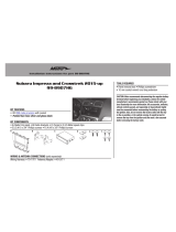
KIT COMPONENTS
• A) Radio trim panel (with touchscreen display) • B) Radio chassis brackets • C) Radio display screen brackets • D) Phillips screws (4)
• E) Antenna adapter (not shown)
KIT FEATURES
• Designed specifically for the Pioneer DMH-C5500NEX 8-inch radio
• Included interface for climate and steering wheel functions
•
Touchscreen display for climate, audio interfacing, and personalization features
• Painted black
Note: Reference the Troubleshooting section for factory items known to
be no longer functional.
TOOLS REQUIRED
• Panel removal tool • Phillips screwdriver
• 9/32” socket wrench • T-20 Torx driver
TABLE OF CONTENTS
Dash Disassembly ...............................................2-3
Kit Assembly ......................................................4-5
Axxess Interface Installation ............................6-15
Final Assembly ...................................................... 11
WIRING & ANTENNA CONNECTIONS
Wiring Harness: Axxess interface built
into touchscreen
Antenna Adapter: Included with kit
Ram 1500/2500/3500, Chassis Cab 3500 /
4500 / 5500 (with 5” or 8” touchscreen) 2013-2017
A B C D
Visit MetraOnline.com for more detailed information about the product and up-to-date vehicle
specific applications

1.800.221.0932
|
MetraOnline.com
DASH DISASSEMBLY
2
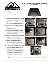
1. Remove the rubber tray liner inside the
tray at the top center of the dash, then
remove (2) Torx T-20 screws exposed.
(Figure A)
2. Remove the rubber tray liner from inside
the small pocket on the passenger side
of the center dash panel, then remove
(1) Torx T-20 screw exposed. (Figure B)
(Figure C)
3. For models with a center console:
a. Remove the rubber liner from the
storage tray in front of the center
console, then remove (2) Phillips
screws exposed. (Figure C)
b. Remove the rubber liner from the
middle of the center console, then
remove (1) Phillips screw exposed.
(Figure C)
c. Models with a column shifter:
Remove the rubber liner from the
rear of the center console, then
remove (2) Phillips screws exposed.
(Figure C)
d. Models with a console shifter:
Pull down on the chrome shifter
trim, then pull up on the shifter
to remove it.
e. Models with a console shifter:
Remove the rubber liner from the
cupholders, then remove (2) 9/32”
screws exposed.
Continued on the next page
(Figure B)
(Figure A)

REV. 8/28/2019 INST108-CH2B
3
DASH DISASSEMBLY
(CONT.)
3
4. Unsnap and remove the entire center
dash panel. (Figure D)
5. Remove (4) 9/32” screws securing the
radio/display screen. Slide the screen
out, then unplug & remove. (Figure E)
6. The factory rear support will need to be
cut or removed to allow space for the
aftermarket radio. Different variations
of this support may require additional
cutting. (Figure F)
Continue to Kit Assembly
(Figure D) (Figure E) (Figure F)
Remove shaded area

1.800.221.0932
|
MetraOnline.com
4
KIT ASSEMBLY
(Figure A)
(Figure B)
1. From the factory center dash panel,
remove (4) Phillips screws securing
the lower button panel, then remove.
(Figure A)
2. From the factory center dash panel,
remove (13) Phillips screws securing
the radio/climate control panel, then
remove. (Figure A)
Note: For steps 3 and 7, reference the
installation manual provided with the radio
for which hardware to use. The display
screen and radio chassis use two different
types of screws.
3. Secure the radio display to the radio
display brackets using (6) screws
supplied with the radio. (Figure B)
Continued on the next page

REV. 8/28/2019 INST108-CH2B
55
KIT ASSEMBLY
(CONT.)
(Figure D) (Figure E)(Figure C)
4. Secure the display/bracket assembly to
the radio trim panel using (4) Phillips
screws provided. (Figure C)
5. Place the radio trim panel with
touchscreen display onto the factory
center dash panel, then secure using
the factory screws removed in step 2.
(Figure D)
6. Secure the lower button panel back to
the factory center dash panel, using the
factory screws removed in step 1.
(Figure D)
7. Secure the radio chassis brackets to the
radio chassis using (4) screws supplied
with the radio. (Figure E)
Continue to Axxess
Interface Installation

1.800.221.0932
|
MetraOnline.com
AXXESS INTERFACE INSTALLATION
6
• Provides accessory power (12-volt 10-amp)
• Retains R.A.P. (retained accessory power)
• Provides NAV outputs (parking brake, reverse, speed sense)
• Retains audio controls on the steering wheel
• Retains safety chimes
• Retains the factory backup camera
• Retains the factory AUX-IN jack
• Can be used in amplified or non-amplified models
• Retains balance and fade*
• Micro-B USB updatable
INTERFACE FEATURES
• Crimping tool and connectors, or solder gun, solder, and heat shrink
• Tape • Wire cutter • Zip ties
TOOLS REQUIRED
• Axxess interface (built into the touchscreen display)
• Main harness
• 16-pin harness with stripped leads
• 4-pin harness with yellow RCA jacks
• 4-pin harness with stripped leads
• Hazard harness
Connections ...............................................................................................................................7-9
Installation ..................................................................................................................................10
Programming .............................................................................................................................. 10
Touchscreen display operation ..............................................................................................12-13
Steering wheel control settings ............................................................................................14-15
Troubleshooting............................................................................................................................15
INTERFACE COMPONENTS
TABLE OF CONTENTS
* Non-amplified models only
Attention! This interface will work with models that are either non-amplified, or amplified.
Please follow the instructions carefully for your model vehicle. Failure to do so will result in
either no sound, or low sound. If you are unsure if your vehicle is factory amplified or not,
please contact your local dealership.

REV. 8/28/2019 INST108-CH2B
7
CONNECTIONS
7
From the main harness to the aftermarket radio:
• Connect the Black wire to the ground wire.
• Connect the Yellow wire to the battery wire.
• Connect the Gray wire to the right front positive speaker output.
• Connect the Gray/Black wire to the right front negative speaker output.
• Connect the White wire to the left front positive speaker output.
• Connect the White/Black wire to the left front negative speaker output.
• Connect the (2) 4-pin connectors together.
• If retaining the factory backup camera, connect the Yellow RCA jack to the reverse
camera input.
• If the AUX-IN jack in the dash is desired to be used, connect the Red and White RCA jacks
to the audio input jacks from the aftermarket radio.
• Tape off and disregard the following (2) wires, they will not be used in this application:
Blue/White labeled “500L amp turn on”, Red
• Disregard the DIN jack, it will not be used in this application.
Continue to 3.5mm jack - steering wheel control retention
For models
without
a factory amplifier:
From the 16-pin harness with stripped leads to the aftermarket radio:
• Connect the Red wire to the accessory wire.
• Connect the Blue/White wire to the amp turn on wire.
• Connect the Orange/White wire to the illumination (lighting switch) wire.
Attention! The following (4) wires are reversed on purpose. These wires will not match “color
code” to the aftermarket radio.
• Connect the Gray wire to the right rear positive speaker output.
• Connect the Gray/Black wire to the right rear negative speaker output.
• Connect the White wire to the left rear positive speaker output.
• Connect the White/Black wire to the left rear negative speaker output.
• Connect the Green/Purple wire to the reverse wire.
• Connect the Light Green wire to the parking brake wire.
• Tape off and disregard the following (6) wires, they will not be used in this application:
Blue/Pink, Brown, Green, Green/Black, Purple, Purple/Black

1.800.221.0932
|
MetraOnline.com
From the main harness to the aftermarket radio:
• Connect the Black wire to the ground wire.
• Connect the Yellow wire to the battery wire.
• Connect the Gray wire to the right front positive speaker output.
• Connect the Gray/Black wire to the right front negative speaker output.
• Connect the White wire to the left front positive speaker output.
• Connect the White/Black wire to the left front negative speaker output.
• Connect the 4-pin harness with stripped leads, to the 4-pin harness on the 52-pin connector.
• Connect the Green wire to the left rear positive speaker output.
• Connect the Green/Black wire to the left rear negative speaker output.
• Connect the Purple wire to the right rear positive speaker output.
• Connect the Purple/Black wire to the right rear negative output.
• If retaining the factory backup camera, connect the Yellow RCA jack to the reverse
camera input.
• If the AUX-IN jack in the dash is desired to be used, connect the Red and White RCA jacks to
the audio input jacks from the aftermarket radio.
• Tape off and disregard the following (2) wires, they will not be used in this application:
Blue/White labeled “500L amp turn on”, Red
• Disregard the DIN jack, it will not be used in this application.
Continue to 3.5mm jack - steering wheel control retention
For models
with
a factory amplifier:
From the 16-pin harness with stripped leads to the aftermarket radio:
• Connect the Red wire to the accessory wire.
• Connect the Blue/White wire to the amp turn on wire. This wire must be connected to hear
sound from the factory amplifier.
• Connect the Orange/White wire to the illumination (lighting switch) wire.
• Connect the Green/Purple wire to the reverse wire.
• Connect the Light Green wire to the parking brake wire.
• Tape off and disregard the following (10) wires, they will not be used in this application:
Blue/Pink, Gray, Gray/Black, White, White/Black, Green, Green/Black, Purple,
Purple/Black, Brown
8
CONNECTIONS
(CONT.)

REV. 8/28/2019 INST108-CH2B
9
3.5mm jack - steering wheel control retention:
The 3.5mm jack is to be used to retain the audio controls on the back of the steering wheel.
• Connect the 3.5mm jack into the wired remote input from the aftermarket radio. Refer to the
manual provided with the radio if in doubt as to where the 3.5mm jack goes to.
4-pin harness with yellow RCA jacks:
• If retaining the factory backup camera to the touchscreen display is desired, connect the
Yellow RCA jack labeled “Rearview camera”, to the Yellow RCA jack from the 6527 harness.
Note: If this method is chosen, the backup camera option must be enabled in
Configuration Settings
.
• Disregard the Yellow RCA jack labeled “AUX video”, it will not be used in this application.
9
CONNECTIONS
(CONT.)

1.800.221.0932
|
MetraOnline.com
10
I N STALL ATI ON PROGRAMMING
It is highly advisable to read the following steps beforehand, to ensure a clear understanding of
what is to be expected. The following steps must be done in the order that they are numbered.
With the vehicle completely off:
1. Connect the 16-pin harness with stripped leads
into port “B” in the touchscreen display.
2. Connect the main harness to the wiring harnesses in the vehicle. These harnesses are the
ones removed in step 7 of dash disassembly. Then insert the
main harness into port “A” in
the touchscreen display. But do not install this harness until exactly before step 1 from the
Programming section. This is a timed process.
3. Connect the 4-pin harness with yellow RCA jacks into port “C” in the touchscreen display.
4. Connect the hazard harness into port “D” in the touchscreen display, and then to the wiring
harness in the vehicle.
5. Disregard port “E”, it will not be used in this application.
6. Port “F” is an update port for future firmware upgrades.
7. Locate the factory antenna connector in the dash and complete all necessary connections to
the radio. Metra recommends using the proper mating adapter from Metra.
A
B
C
E
F
D
1. Refer to step 2 from the Installation section.
2. Press the push-to-start button to start the vehicle.
3. Program the kit:
a. Once the touchscreen display loads up, select the vehicle type.
b. Wait until the radio comes on, and the touchscreen display shows SWC Configured*.
This process may take up to 3 minutes.
Note: If the touchscreen display does not load up, or the radio doesn’t come on within
3 minutes, and/or the touchscreen display does not show SWC Configured*, check all
connections, then reset the interface and try again. Refer to the Troubleshooting section.
4.
Cycle the key off. If the driver’s door is closed, open and close the door. Cycle the key back on.
5. Test all functions of the installation for proper operation, before reassembling the dash.
Note: Refer to the Troubleshooting section for factory items known to be no longer functional
.
Note: DO NOT CONNECT!

REV. 8/28/2019 INST108-CH2B
11
1. Slide the radio chassis into the dash and
secure using the factory screws.
2. Clip the center dash panel and radio
display assembly to the vehicle, then
reassemble the center console and
dash in reverse order of disassembly to
complete the installation.
FINAL ASSEMBLY

1.800.221.0932
|
MetraOnline.com
12
TOUCHSCREEN DISPLAY OPERATION
• This is the climate control screen which will be displayed on the touchscreen display.
This is considered the Main Menu.
• The upper left tab with (3) arrows will take you to the screen where the Heated/Cooled
Seats are now placed, if applicable.
• The upper right tab with a gear icon will take you to the Configuration Settings screen.
• The climate controls will function in the same manner that they did with the factory climate
controls.
• For models with rear climate controls, the button labeled “REAR” will take you to the rear
climate control menu.
Continued on the next page
Climate Control screen

REV. 8/28/2019 INST108-CH2B
1313
TOUCHSCREEN DISPLAY OPERATION
(CONT.)
Configuration Settings
• Display
• Backlight - For controlling the color of the buttons
and back-light intensity.
• Language
• Units
• Safety & Driving Assistance - Factory features
• Lights - Factory features
• Doors & Locks - Factory features
• Engine Off Options - Factory features
• Steering Wheel Controls
• Remap Buttons – For remapping the steering
wheel control buttons
• Dual Assign – For dual assigning the steering wheel
control buttons (long button press)
• Select Radio – For auto detecting the radio, or
changing the radio type
• Digital Amp Gain - For adjusting the output gain
to the amplifier
• System Configuration
• About - Information regarding the software in the kit
• Reset Vehicle Type - To reset the kit to default settings
• Comfort Options Override - Provides the ability to
disable/enable certain factory options
• Backup Camera
• Enable/disables the backup camera image to the
touchscreen display. Disabled by default.

1.800.221.0932
|
MetraOnline.com
14
STEERING WHEEL CONTROL SETTINGS
(CONT.)
STEERING WHEEL CONTROL SETTINGS
Remap Buttons Dual Assign
• The interface has the ability to change the button assignment for the steering wheel
control audio buttons, except Volume-Up and Volume-Down. Follow the
prompts on the touchscreen display to remap the steering wheel control audio button(s)
to your liking.
Note: The aftermarket radio may not have all of these commands. Please refer to the
manual provided with the radio, or contact the radio manufacturer, for specific commands
recognized by that particular radio.
• The interface has the capability to assign two functions to a single button, except
Volume-Up and Volume-Down. Follow the prompts on the touchscreen display to program
the button(s) to your liking.
Note: Seek-Up and Seek-Down come programmed as Preset-Up and Preset-Down
for a long button press.
Continued on the next page

REV. 8/28/2019 INST108-CH2B
15
Resetting the interface
1. With the vehicle running, press the Reset Vehicle Type button mentioned in System
Configuration.
2. Refer to Programming, step 3, from this point.
Known items non-functioning
At the time of this writing, these are the items that are known to be lost. Please check back in
the future for a possible update to retain these items.
1. Clock and compass in the driver’s information center.
2. The ability to adjust the Active-Level Four Corner Air-Suspension.
3. 5th wheel camera.
4. Trailer brake adjustments.
5. Key fob controller settings.
TROUBLESHOOTING
15
STEERING WHEEL CONTROL SETTINGS
(CONT.)
Select Radio
• To show which brand radio is “auto detected” by the interface, press the “Autodetect”
button. The radio detected will have a filled in circle. If the incorrect radio is shown,
select Pioneer.
Note: If the interface shows an Alpine radio, that means the interface does not detect a radio
connected it, i.e., an open connection. Verify that the 3.5mm jack is connected to the correct
steering wheel jack in the radio.

Metra. The World’s Best Kits.
®
MetraOnline.com © COPYRIGHT 2019 METRA ELECTRONICS CORPORATION REV. 7/30/19 INST108-CH2B
INSTALLATION INSTRUCTIONS
108-CH2B
KNOWLEDGE IS POWER
Enhance your installation and fabrication skills by
enrolling in the most recognized and respected
mobile electronics school in our industry.
Log onto www.installerinstitute.com or call
800-354-6782 for more information and take steps
toward a better tomorrow.
®
Metra recommends MECP
certified technicians
If you are having difficulties with the installation
of this product, contact our Tech Support line
either by phone at 386-257-1187, or email at
techsupport@metra-autosound.com. Before
doing so, look over the instruction booklet a
second time and ensure that the installation was
performed exactly as the instruction booklet
is stated. Have the vehicle apart and ready to
perform troubleshooting steps before contacting
Metra/Axxess Tech Support.
/