4. Specifications
Technical
HDCP Compliance HDCP 2.2/1.4
Input Video Formats
ESD Protection Human-body Model:
±8kV (Air-gap discharge) , ±4kV (Contact discharge)
RS-232 Baud rate57600, data bit8, Stop bit1, no parity
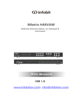
5. Operation Controls and Functions
Front Panel
- 2 / 12 -
HDMI Compliance HDMI 2.0
Mechanical
Housing Metal Enclosure
Color Black
Dimension 430mm (W)×220mm (D)×44mm (H)
Weight 5Kg
Supply Voltage 110-220V AC
0°C ~ 40°C / 32°F ~ 104°F
-20°C ~ 70°C / -4°F ~ 158°F
Operating Temperature
Storage Temperature
Relative Humidity 10%~50% RH (non-condensing)
Audio Format 2.0 channel, 5.1 channel, LPCM, Dolby, AC3, DTS
12 4
3
1024x768@60, 1280x800@60, 1280x1024@60,
1280x960@60, 1360x768@60, 1366x768@60,
1440x900@60, 1400x1050@60, 1600x900@60,
1600x1200@60, 1680x1050@60, 1920x1200@60,
480p@60, 576p@50, 720p@50, 720p@60, 1080i@50,
1080i@60, 1080p@24, 1080p@25, 1080p@30, 1080p@50
1080p@60, 3840x2160@24, 3840x2160@25,
3840x2160@30, 3840x2160@50, 3840x2160@60,
4096x2160@24, 4096x2160@30, 4096x2160@50,
4096x2160@60
OUTPUT
HD 8
PWR LP B
HD A HD B
INPUT
LP A HD 7
HD 6
HD 5
HD 4
HD 3
HD 2HD 1 HD 9
HHDDMMII 22..00 VViidd ee oo WWaa llll PPrroo ccee ss ssoo rr
LOOP