Page is loading ...

EQ 100
Video Equalizer
68-162-01
Printed in USA
System 4xi Series
System 4LQxi • Switcher/Line Quadrupler
System 4LDxi • Switcher/Line Doubler

This symbol is intended to alert the user of important operating and maintenance
(servicing) instructions in the literature provided with the equipment.
This symbol is intended to alert the user of the presence of uninsulated dangerous
voltage within the product's enclosure that may present a risk of electric shock.
Caution
Read Instructions • Read and understand all safety and operating instructions before using the
equipment.
Retain Instructions • The safety instructions should be kept for future reference.
Follow Warnings • Follow all warnings and instructions marked on the equipment or in the user
information.
Avoid Attachments • Do not use tools or attachments that are not recommended by the equipment
manufacturer because they may be hazardous.
Warning
Power sources • This equipment should be operated only from the power source indicated on the
product. This equipment is intended to be used with a main power system with a grounded
(neutral) conductor. The third (grounding) pin is a safety feature, do not attempt to bypass or
disable it.
Power disconnection • To remove power from the equipment safely, remove all power cords from
the rear of the equipment, or the desktop power module (if detachable), or from the power
source receptacle (wall plug).
Power cord protection • Power cords should be routed so that they are not likely to be stepped on or
pinched by items placed upon or against them.
Servicing • Refer all servicing to qualified service personnel. There are no user-serviceable parts
inside. To prevent the risk of shock, do not attempt to service this equipment yourself because
opening or removing covers may expose you to dangerous voltage or other hazards.
Slots and openings • If the equipment has slots or holes in the enclosure, these are provided to
prevent overheating of sensitive components inside. These openings must never be blocked by
other objects.
Lithium battery • There is a danger of explosion if battery is incorrectly replaced. Replace it only with
the same or equivalent type recommended by the manufacturer. Dispose of used batteries
according to the manufacturer's instructions.
Ce symbole sert à avertir l’utilisateur que la documentation fournie avec le matériel
contient des instructions importantes concernant l’exploitation et la maintenance
(réparation).
Ce symbole sert à avertir l’utilisateur de la présence dans le boîtier de l’appareil de
tensions dangereuses non isolées posant des risques d’électrocution.
Attention
Lire les instructions• Prendre connaissance de toutes les consignes de sécurité et d’exploitation avant
d’utiliser le matériel.
Conserver les instructions• Ranger les consignes de sécurité afin de pouvoir les consulter à l’avenir.
Respecter les avertissements • Observer tous les avertissements et consignes marqués sur le matériel ou
présentés dans la documentation utilisateur.
Eviter les pièces de fixation • Ne pas utiliser de pièces de fixation ni d’outils non recommandés par le
fabricant du matériel car cela risquerait de poser certains dangers.
Avertissement
Alimentations• Ne faire fonctionner ce matériel qu’avec la source d’alimentation indiquée sur
l’appareil. Ce matériel doit être utilisé avec une alimentation principale comportant un fil de
terre (neutre). Le troisième contact (de mise à la terre) constitue un dispositif de sécurité :
n’essayez pas de la contourner ni de la désactiver.
Déconnexion de l’alimentation• Pour mettre le matériel hors tension sans danger, déconnectez tous
les cordons d’alimentation de l’arrière de l’appareil ou du module d’alimentation de bureau (s’il
est amovible) ou encore de la prise secteur.
Protection du cordon d’alimentation • Acheminer les cordons d’alimentation de manière à ce que
personne ne risque de marcher dessus et à ce qu’ils ne soient pas écrasés ou pincés par des objets.
Réparation-maintenance • Faire exécuter toutes les interventions de réparation-maintenance par un
technicien qualifié. Aucun des éléments internes ne peut être réparé par l’utilisateur. Afin
d’éviter tout danger d’électrocution, l’utilisateur ne doit pas essayer de procéder lui-même à ces
opérations car l’ouverture ou le retrait des couvercles risquent de l’exposer à de hautes tensions
et autres dangers.
Fentes et orifices • Si le boîtier de l’appareil comporte des fentes ou des orifices, ceux-ci servent à
empêcher les composants internes sensibles de surchauffer. Ces ouvertures ne doivent jamais
être bloquées par des objets.
Lithium Batterie • Il a danger d'explosion s'll y a remplacment incorrect de la batterie. Remplacer
uniquement avec une batterie du meme type ou d'un ype equivalent recommande par le
constructeur. Mettre au reut les batteries usagees conformement aux instructions du fabricant.
Safety Instructions • English
Consignes de Sécurité • Français
Sicherheitsanleitungen • Deutsch
Dieses Symbol soll den Benutzer auf wichtige Anleitungen zur Bedienung und
Wartung (Instandhaltung) in der Dokumentation hinweisen, die im Lieferumfang
dieses Gerätes enthalten ist.
Dieses Symbol soll den Benutzer darauf aufmerksam machen, daß im Inneren des
Gehäuses dieses Produktes gefährliche Spannungen, die nicht isoliert sind und
die einen elektrischen Schock verursachen können, herrschen.
Achtung
Lesen der Anleitungen • Bevor Sie das Gerät zum ersten Mal verwenden, sollten Sie alle Sicherheits-und
Bedienungsanleitungen genau durchlesen und verstehen.
Aufbewahren der Anleitungen • Die Sicherheitsanleitungen sollten aufbewahrt werden, damit Sie
später darauf zurückgreifen können.
Befolgen der Warnhinweise • Befolgen Sie alle Warnhinweise und Anleitungen auf dem Gerät oder in
der Benutzerdokumentation.
Keine Zusatzgeräte • Verwenden Sie keine Werkzeuge oder Zusatzgeräte, die nicht ausdrücklich vom
Hersteller empfohlen wurden, da diese eine Gefahrenquelle darstellen können.
Vorsicht
Stromquellen • Dieses Gerät sollte nur über die auf dem Produkt angegebene Stromquelle betrieben
werden. Dieses Gerät wurde für eine Verwendung mit einer Hauptstromleitung mit einem
geerdeten (neutralen) Leiter konzipiert. Der dritte Stift oder Kontakt ist für einen Erdschluß, und
stellt eine Sicherheitsfunktion dar und sollte nicht umgangen oder außer Betrieb gesetzt werden.
Stromunterbrechung • Um das Gerät auf sichere Weise vom Netz zu trennen, sollten Sie alle
Netzkabel aus der Rückseite des Gerätes oder aus dem Desktop-Strommodul (falls dies möglich
ist) oder aus der Wandsteckdose ziehen.
Schutz des Netzkabels • Netzkabel sollten stets so verlegt werden, daß sie nicht im Weg liegen und
niemand darauf treten kann oder Objekte darauf- oder unmittelbar dagegengestellt werden
können.
Wartung • Alle Wartungsmaßnahmen sollten nur von qualifiziertem Servicepersonal durchgeführt
werden. Im Inneren des Gerätes sind keine Teile enthalten, die vom Benutzer gewartet werden können.
Zur Vermeidung eines elektrischen Schocks versuchen Sie in keinem Fall, dieses Gerät selbst zu
warten, da beim Öffnen oder Entfernen der Abdeckungen die Gefahr eines elektrischen Schlags
oder andere Gefahren bestehen.
Schlitze und Öffnungen • Wenn das Gerät Schlitze oder Löcher im Gehäuse aufweist, dienen diese
zur Vermeidung einer Überhitzung der empfindlichen Teile im Inneren. Diese Öffnungen dürfen
niemals von anderen Objekten blockiert werden.
Litium-Batterie • Explosionsgefahr, falls die Batterie nicht richtig ersetzt wird. Ersetzen Sie nur durch
die gleiche oder einen vergleichbaren Batterietyp, der auch vom Hersteller empfohlen wird.
Entsorgung der verbrauchten Batterien bitte gemäß den Herstelleranweisungen.
Este símbolo se utiliza para advertir al usuario sobre instrucciones importantes de
operación y mantenimiento (o cambio de partes) que se desean destacar en el
contenido de la documentación suministrada con los equipos.
Este símbolo se utiliza para advertir al usuario sobre la presencia de elementos con
voltaje peligroso sin protección aislante, que puedan encontrarse dentro de la caja
o alojamiento del producto, y que puedan representar riesgo de electrocución.
Precaucion
Leer las instrucciones • Leer y analizar todas las instrucciones de operación y seguridad, antes de usar
el equipo.
Conservar las instrucciones • Conservar las instrucciones de seguridad para futura consulta.
Obedecer las advertencias • Todas las advertencias e instrucciones marcadas en el equipo o en la
documentación del usuario, deben ser obedecidas.
Evitar el uso de accesorios • No usar herramientas o accesorios que no sean especificamente
recomendados por el fabricante, ya que podrian implicar riesgos.
Advertencia
Alimentación eléctrica • Este equipo debe conectarse únicamente a la fuente/tipo de alimentación
eléctrica indicada en el mismo. La alimentación eléctrica de este equipo debe provenir de un
sistema de distribución general con conductor neutro a tierra. La tercera pata (puesta a tierra) es
una medida de seguridad, no puentearia ni eliminaria.
Desconexión de alimentación eléctrica • Para desconectar con seguridad la acometida de
alimentación eléctrica al equipo, desenchufar todos los cables de alimentación en el panel trasero
del equipo, o desenchufar el módulo de alimentación (si fuera independiente), o desenchufar el
cable del receptáculo de la pared.
Protección del cables de alimentación • Los cables de alimentación eléctrica se deben instalar en
lugares donde no sean pisados ni apretados por objetos que se puedan apoyar sobre ellos.
Reparaciones/mantenimiento • Solicitar siempre los servicios técnicos de personal calificado. En el
interior no hay partes a las que el usuario deba acceder. Para evitar riesgo de electrocución, no
intentar personalmente la reparación/mantenimiento de este equipo, ya que al abrir o extraer las
tapas puede quedar expuesto a voltajes peligrosos u otros riesgos.
Ranuras y aberturas • Si el equipo posee ranuras o orificios en su caja/alojamiento, es para evitar el
sobrecalientamiento de componentes internos sensibles. Estas aberturas nunca se deben obstruir
con otros objetos.
Batería de litio • Existe riesgo de explosión si esta batería se coloca en la posición incorrecta. Cambiar
esta batería únicamente con el mismo tipo (o su equivalente) recomendado por el fabricante.
Desachar las baterías usadas siguiendo las instrucciones del fabricante.
Instrucciones de seguridad • Español
Precautions

Contents
Extron • System 4
xi
Switcher Series • User’s Manual
System 4
xi
Switcher Series
Getting Started..........
tt
Step 1
uu
If the System 4xi is already configured for your model of projector, go to
Step 4
. If it is not set
up correctly, it will be necessary to change switch settings on the System 4xi ’s Main
Controller Board. Continue with
Step 2
below to verify the correct configuration.
tt
Step 2
uu
Apply power to the System 4xi. Use the front panel to display the Information Menu (Menu 8).
If the configuration is correct, go to
Step 4
. If it is not correct, continue with
Step 3
.
tt
Step 3
uu
Go to the procedure on page 2-3 of the
System 4
xi
User’s Manual
to remove the System 4xi
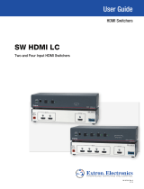
cover. Then go to page 2-4 for instructions on configuring the Main Controller board. The
following table and diagram are to be used only as examples of a typical configuration. Please
consult either the label inside the System 4xi top cover or the
System 4
xi
Projector
Communications Kit
instructions for the correct configuration settings. Continue with
Step 4
below when your configuration is correct.
Config Projector SW1: 1-2-3-4 SW2 SW3 SW4 SW5 SW6 Prj Cable Comm
as Adapter
✔ Your Model off-on-off-on 0 1 0 5 0 J15 26-467-01
tt
Step 4
uu
Double-check your work and be sure the System 4xi cover is back on securely.
tt
Step 5
uu
Please refer to the appropriate connection diagram for your projector (see your
System 4
xi
Projector Communications Kit
instructions). Using the appropriate Communications Adapter
included in your Communications Kit, connect the Comm extension cable from the PJ Comm
port of the System 4xi to the Comm Adapter. Secure the Comm Adapter to the appropriate
projector port.
tt
Step 6
uu
Connect the RGBS/HV cable from the System 4xi output BNC connectors to the projector’s
matching RGBS/HV input connectors. Verify that all your connections are correct. If in
doubt, please refer to the specific installation instructions which were included in your
Communications Kit.
SW1
SW2
SW6
SW3
SW5
J15
3
4
1
2
SW4

Extron • System 4
xi
Switcher Series • User’s Manual
Contents

Contents
Extron • System 4
xi
Switcher Series • User’s Manual
CONTENTS
Chapter One - System 4xi Series - Introduction and Features
Introduction to System 4xi ....................................................................................................... 1-1
System 4xi Features .................................................................................................. 1-2
Specifications.......................................................................................................................... 1-4
Chapter Two - Configuration and Installation
Rear Panel Connectors and Indicators ................................................................................... 2-1
Projector/Monitor Applications................................................................................................. 2-2
Communications Adapters and Cables ...................................................................... 2-3
User-Supplied Cables ................................................................................................ 2-3
Removing the System 4xi Cover ............................................................................................. 2-3
Setting the Main Controller Board for the Projector................................................................. 2-4
Cabling a System 4xi in a Rack............................................................................................... 2-5
Audio Terminal Connections ................................................................................................... 2-6
Audio Wiring Applications........................................................................................... 2-6
Chapter Three - Using the System 4xi Front Panel
Front Panel ............................................................................................................................. 3-1
Main Power................................................................................................................ 3-1
Inputs ......................................................................................................................... 3-1
Display Controls......................................................................................................... 3-1
Picture Controls ......................................................................................................... 3-1
Breakaway ................................................................................................................. 3-1
Audio Mute................................................................................................................. 3-1
Menu Controls............................................................................................................ 3-1
LCD Display............................................................................................................... 3-1
Default LCD Screen................................................................................................................ 3-2
System 4xi Model Differences................................................................................................. 3-2
Menu Controls and Navigation................................................................................................ 3-3
Terms used in LCD Menus......................................................................................... 3-3
Example of Using the Menu Controls......................................................................... 3-4
Menu System............................................................................................................. 3-7
Menu Select/Exit Menu ................................................................................. 3-7
Video Mode Configuration............................................................................. 3-7
Video Mode Configuration Menu ................................................................... 3-7
Audio Level Configuration Menu ................................................................... 3-8
Host Baudrate Menu ..................................................................................... 3-8
RGB Delay Menu .......................................................................................... 3-8
Slave Configuration Menu ............................................................................. 3-9
LD Sync Configuration Menu ........................................................................ 3-9
Sync Configuration Menu .............................................................................. 3-9
Information Menu ......................................................................................... 3-10
Slave Switcher Input Selection..................................................................... 3-10
Picture Controls (line-doubler/line-quadrupler converter) ....................................................... 3-10
Horizontal Shift Control ............................................................................................. 3-11
Contrast Control........................................................................................................ 3-11
Color Control............................................................................................................. 3-11
Tint Control ............................................................................................................... 3-11
Detail Control ............................................................................................................ 3-11
i

Extron • System 4
xi
Switcher Series • User’s Manual
Contents
ii
System 4xi Series LCD Menus .............................................................................................. 3-12
Special Functions .................................................................................................................. 3-13
System Reset ........................................................................................................... 3-13
Toggle Executive Mode............................................................................................. 3-13
Chapter Four - Connecting Multiple Switchers
Looping the System 4xi with Other Switchers ......................................................................... 4-1
Input Channel Addressing .......................................................................................... 4-1
Controlling Master/Slave Switchers............................................................................ 4-2
System 4xi with SW4/6 ARMX Switchers................................................................... 4-3
System 4xi with One System 8/10 PLUS Switcher....................................................... 4-4
System 4xi with Multiple System 8/10 PLUS Switchers................................................ 4-5
System 8/10 Plus Switch Settings.............................................................................. 4-6
Programming the System 4xi Looping Configuration .............................................................. 4-7
Testing the Master/Slave Communications ................................................................ 4-7
Chapter Five – Using Windows® Control Software
Extron System Switcher Control Software .............................................................................. 5-1
System 4xi Help (examples)....................................................................................... 5-2
Executive Mode ......................................................................................................... 5-4
Window Pull-Down Menus ......................................................................................... 5-4
Appendix A - RS-232 Programming Guide
Programming the System 4xi Series Switchers....................................................................... A-1
RS-232 Connections.................................................................................................. A-1
RS-232 Protocol ........................................................................................................A-1
Program Instruction Levels ........................................................................................ A-1
System 4xi-Initiated Messages ............................................................................................... A-2
Simple Instruction Set ............................................................................................................. A-3
Related Terms............................................................................................................ A-3
Simple Instruction List (with examples) ...................................................................... A-4
Simple Instruction Examples......................................................................................A-5
Selecting Inputs Using Delimiters............................................................................... A-7
Advanced Instruction Set ........................................................................................................ A-8
Advanced Instruction List........................................................................................... A-8
Error Codes (ERC) .................................................................................................... A-8
Hex, Decimal and Binary Examples for Converting Range Values............................. A-9
Select Input - CMD4 (34h) .........................................................................................A-9
Request Status - CMD5 (35h)................................................................................... A-10
Change System Settings - CMD6 (36h) .................................................................... A-11
Set Slave Configuration - CMD8 (38h)...................................................................... A-11
Configure an Input Channel - CMD9 (39h)................................................................ A-12
Request Input Channel Configuration - CMD10 (3Ah) .............................................. A-13
Configure System - CMD11 (3Bh).............................................................................A-14
Request System Configuration - CMD12 (3Ch) ........................................................ A-15
Appendix B - General Reference Information
System 4xi Related Parts List ................................................................................................. B-1
Changing the Main Fuse......................................................................................................... B-2
Les câbles fournis à l’utillsasteur ............................................................................................ B-3
(French) Enlever le couvercle du Système 4.......................................................................... B-3
Câbler un Système 4 sur un rack............................................................................................ B-4
(German) Entfernung der System 4 Abdeckung..................................................................... B-5

Contents
Extron • System 4
xi
Switcher Series • User’s Manual
iii
Verkabelung vom System 4 innerhalb eines Gestells ............................................................. B-6
Upgrading Main Controller Board Software and Battery Replacement.................................... B-7
Legend of Icons
_________ Important information – for example, an action or a step that must be done
before proceeding.
_________ A Warning – possible dangerous voltage present.
_________ A Warning – possible damage could occur.
_______ A Note, a Hint, or a Tip that may be helpful.
________ Possible Electrostatic Discharge (ESD) damage could result from touching
electronic components.
________ Indicates word definitions. Additional information may be referenced in another
section, or in another document.
Extron’s System 4
xi
User’s Manual
68-162-01
First edition – Rev A, 59-07
Second edition – Rev B, 79-02
Third edition – Rev C, 99-12
New format without projectors

Extron • System 4
xi
Switcher Series • User’s Manual
Contents

1
System 4
xi
Switcher Series
User’s Manual
Introduction and Features
System 4
xi
Features
Projector/Monitor Applications
RGB Decoder, Line Doubler and Line Quadrupler
Specifications
Chapter One

Chapter 1 • Introduction and Features
Extron • System 4
xi
Switcher Series • User’s Manual
OUTPUT
PJ COMM
RS 232
AUDIO AUDIO AUDIO AUDIO AUDIO
H/HV
R/C G/Y BR/C G/Y B
V
INPUT 4
H/HV V
R/C G/Y B
INPUT 3
H/HV V
R/C G/Y B
INPUT 2
H/HV V
R/C G/Y B
INPUT 1
H/HV V
Control
System
Large Screen
Projector
VCR/VTR with Audio
Laserdisc Player
with S-VHS Outputs
and Stereo Audio
SGI/SUN
Workstation
PC or Workstation
with Audio
Stereo Audio
RGB
Interface
RGB
Interface
Introduction to System 4xi
EXTRON’S System 4xi Series of switchers (henceforth to be referred to as System
4xi ) combines the features of a projector-controlling switcher and a line-doubler
or line-quadrupler into a rack-mountable enclosure with an internal power supply.
The System 4xi ’s four video inputs can be any combination of the formats listed
below and the output will always be RGB. Four stereo audio inputs are also
available and can be selected following or separated from the selected video
input.
•
Composite Video (NTSC/PAL)
•
S-video/S-VHS (YC)
•
RGBS (NTSC/PAL)
•
RGBS (RGB w/separate composite sync)
•
RGsB (RGB w/sync on green)
•
RGBHV (RGB w/separate H&V sync)
Figure 1-1. Example of a System 4LD
xi
Switcher with Input and Output Devices
The System 4xi has a built-in communications interface that allows it to control
projectors made by companies listed below through their switcher control port.
Please consult Extron for projector manufacturers not listed here.
•
Ampro
•
NEC/Runco
•
Barco
•
Panasonic
•
Digital Projection
•
Sanyo
•
Eiki
•
Seleco
•
Electrohome
•
Sharp
•
Hughes/JVC
•
Sony
•
Infocus
•
Toshiba
•
Mitsubishi
•
Zenith
1-1

Chapter 1 • Introduction and Features
Extron • System 4
xi
Switcher Series • User’s Manual
System 4xi Features
Universal Video Inputs
The System 4xi has four universal inputs, each capable of accepting all computer
RGB signals from 15 kHz to 150 kHz, any composite video standard signals
(NTSC or PAL) and S-video (S-VHS) signals. There are no optional modules to
purchase for each input signal type.
Quad-standard Decoder
The System 4xi is compatible with all standard video formats including NTSC
3.58, NTSC 4.43, PAL and SECAM.
Balanced/Unbalanced Audio Inputs
Every System 4xi is capable of switching up to four balanced or unbalanced, left
and right stereo audio signals. Audio, input through professional-style captive
screw connectors, can be switched to follow any video or RGB input signal, or it
may be switched separately for added flexibility (see “Breakaway” below).
Audio Follow/Breakaway
When switching inputs, the System 4xi can either select audio and video from the
same source (Audio Follow) or select audio from one source and video from
another (Breakaway).
Three-line Adaptive Comb Filter
A built-in, three-line adaptive comb filter helps to provide a crisp, stable output
from the System 4LDxi and 4LQxi.
Built-In Line Doubler/Quadrupler (scan doubler/quadrupler)
The System 4LDxi and 4LQxi include a built-in NTSC or PAL compatible line
doubler or line quadrupler (4LQxi only) that is capable of line-doubling/
quadrupling composite video, S-video or RGB video (Targa or document
camera) signals. The signal also passes through a digital noise filter to improve
the picture. The line-doubled/quadrupled output results in a sharper image with
less noticeable scan lines and “video noise.”
300 MHz RGB Video Bandwidth
The 300 MHz RGB video bandwidth of the System 4xi makes it two to three
times the performance of any other presentation switcher.
LCD Menu-Driven Picture and Programming Controls
The System 4LDxi ’s LCD menu makes setup and programming of its features
and functions easy and flawless. An alphanumeric display allows for any of the
line-doubler/quadrupler controls such as color, hue and contrast to be adjusted
to exact specifications for each input.
RGB Output
The System 4xi video output will be RGBS or RGBHV if the selected input is
configured to be line-doubled or line-quadrupled. If the selected input is not
configured to be line-doubled/quadrupled, the output video format will be the
same as the input.
RS-232 Control
The System 4xi has built-in RS-232 control for external/third party control of any
of its features or functions.
Triple-Action Switching™ RGB Delay Switching
Triple-Action Switching makes it possible to have “seamless” picture switching.
The System 4xi may be programmed to switch the RGB signals to the projector
at a specified time after the sync is switched (0 to 5 seconds, in 1/2 second
increments). The audience will briefly see a blank screen while the projector
“locks on” to the input signal.
1-2

Chapter 1 • Introduction and Features
Extron • System 4
xi
Switcher Series • User’s Manual
Multiple Switcher Applications
The features of the System 4xi can be further expanded by connecting the output
from another switcher to Input #4. The System 4xi then functions as the “master”,
communicating with the projector and providing it with a signal improved by any
of the features described in this section and, if required, can even control the
connected projector using their IR (Infra-Red) remote control, RS-232 control, or
the built-in LCD menu-driven System 4xi front panel control.
Picture Control Memory
All inputs, including those in multiple switcher applications, have a separate
memory block for all picture controls of video or RGB and audio signals. When a
different video input is selected, the picture controls are updated automatically
from the information stored in the Picture Control Memory. RGB inputs in pass-
through mode have no stored picture control information.
Internal Power Supply with Automatic Switching
The System 4xi is equipped with an internal auto-switching power supply that
operates from any input voltage in the 100-240 VAC range, at 50/60Hz.
Universal Projector Control
The E
XTRON System 4xi and the projector operate as a system that can be
controlled several ways:
•
through existing projector controls
•
through the System 4
xi
panel
•
through a host system using the RS-232 port
•
using Extron’s Windows® Control software
Using the projector-brand remote control, the System 4xi can be made to control
the following operations:
•
switch inputs
•
control projector power
•
mute the audio or video signals
•
switch input memory blocks (in projector) for convergence
• setup saved configurations within the connected projector by input selection
•
monitor the projector for update changes, feature changes, or input selection
changes by the user
The above operations can also be accomplished by using the System 4xi front
panel controls or through a PC or other control system. The System 4xi switcher
will communicate with the projector and pass it the desired command.
When a projector manufacturer introduces a new model, the System 4xi can be
upgraded to accommodate it by a simple EPROM change (free during the
warranty period of two years). When a totally new projector brand and model is
introduced, Extron will either add it to the compatibility list for EPROM upgrades,
or make it an available “standard” with all future System 4xi switchers. Call
Extron with details of your requirements.
The unique control features of the System 4xi make using its switcher functions
exactly the same as using the projector-brand switcher, but with a 300 MHz
bandwidth performance — nearly three times that of most projector- brand
switchers.
_______ Some projector IR remotes do not communicate with the System 4
xi
. Also, all
projectors have different methods for source and memory recall of source inputs.
Please refer to your specific installation instructions for further details.
1-3

Chapter 1 • Introduction and Features
Extron • System 4
xi
Switcher Series • User’s Manual 1-4
Specifications
Video input
Number/type.............................. 4 universal inputs (RGBHV, RGBS, RGsB, RsGsBs, S-video, composite video)
Connectors................................ 4 x 5 BNC female
Nominal level(s) ........................ Analog — 0.3V to 1.45V p-p
Maximum level(s)...................... Analog — 2V p-p
Impedance ................................ 75 ohms (deselected inputs)
Horizontal frequency................. 15 kHz to 150 kHz
Vertical frequency ..................... 30 Hz to 150 Hz
Return loss ................................ -30dB @ 5 MHz
Video throughput
Gain........................................... Unity
Bandwidth ................................. 300 MHz (-3dB)
Crosstalk ................................... -80dB @ 3.58 MHz
Switching speed........................ 5 mS (max.)
Video output
Number/type/format .................. System 4LDxi................... 1 RGBHV, RGBS, RGsB, line-doubled video
System 4LQxi................... 1 RGBHV, RGBS, RGsB, line-quadrupled video
Connectors................................ 5 BNC female
Nominal level ............................ 1V p-p
Impedance ................................ 75 ohms
Return loss ................................ -25dB @ 10 MHz
DC offset ................................... ±5 mV maximum
Switching type........................... Triple action, 0 S to 5 S, adjustable
Sync
Input type .................................. RGBHV, RGBS, RGsB, RsGsBs
Output type................................ RGBHV, RGBS, RGsB, RsGsBs
Standards.................................. NTSC 3.58, NTSC 4.43, PAL, SECAM
Input level.................................. 0.5V to 5V p-p
Output level ............................... 0.5V to 5V p-p
Input impedance ....................... 510 ohms (deselected inputs)
Output impedance..................... 75 ohms
Max input voltage...................... 5V p-p
Max. propagation delay ............ 5 nS
Max. rise/fall time...................... 5 nS
Polarity ...................................... Positive or negative (follows input)
Audio input
Number/type.............................. 4 stereo, balanced/unbalanced
Connectors................................ 4 5 mm captive screw terminals, 6 conductor
Impedance ................................ Unbalanced ...................... 10 kohms, AC coupled
Balanced .......................... 20 kohms, AC coupled
Maximum level .......................... +11.2dBu, (balanced or unbalanced) @ stated %THD+N
Input gain adjustment ............... –95.5dB to +31.5dB, adjustable per input
Audio throughput
Frequency response ................. ±0.05dB @ 20 Hz to 20 kHz
THD + Noise ............................. 0.002% @ 1 kHz at rated maximum output drive
S/N ............................................ >95dB
Adjacent input crosstalk............ >85dB @ 20 Hz to 20 kHz
Stereo channel separation........ >60dB @ 20 Hz to 20 kHz
CMRR........................................ >60dB @ 20 Hz to 20 kHz

Chapter 1 • Introduction and Features
Extron • System 4
xi
Switcher Series • User’s Manual1-5
Audio output
Number/type.............................. 1 stereo, balanced/unbalanced
Connectors................................ 5 mm captive screw terminal, 6 conductor
Impedance ................................ 50 ohms, unbalanced; 100 ohms, balanced
Gain error .................................. ±0.2dB channel to channel
Drive (HI-Z) ............................... > +17.2dBu, balanced or unbalanced at stated %THD+N
Drive (600 ohm) ........................ > +17.2dBu, balanced or unbalanced at stated %THD+N
Control/Remote — switcher
Serial control port...................... RS-232, 9-pin female D connector
Baud rate and protocol ............. 9600, 8-bit, 1 stop bit, no parity
Pin configurations ..................... 2 = TX, 3 = RX, 5 = GND
Program control ........................ Extron’s Windows® control program
Extron’s Simple Instruction Set - SIS
Extron’s Advanced Instruction Set - AIS
Control — projector
Projector control port ................ 1 15-pin HD female connector
General
Power ........................................ 100VAC to 240VAC, 50/60 Hz, 20 Watts, internal, auto-switchable
Temperature/humidity............... Storage -40° to +158°F (-40° to +70°C) / 10% to 90%, non-condensing
Operating +32° to +122°F (0° to +50°C) / 10% to 90%, non-condensing
Rack mount ............................... Yes, with attached rack ears
Enclosure type .......................... Metal
Enclosure dimensions............... 1.75" H x 19" W x 16.2" D
4.4 cm H x 48.3 cm W x 41.2 cm D
Shipping weight ........................ 17 lbs (7.7 kg)
DIM weight ....................... 21
Vibration .................................... NSTA 1A in carton (National Safe Transit Association)
Approvals .................................. UL, CUL, CE
MTBF......................................... 30,000 hours
Warranty.................................... 2 years parts and labor
Specifications are subject to change without notice.
19.0"

System 4
xi
Switcher Series
User’s Manual
Configuration and Installation
Rear Panel Connectors and Indicators
Projector/Monitor Applications
Removing the Cover
Setting the Main Controller Board
Rack Mounting
Audio Connections
Connecting to Projectors/Monitors
2
Chapter Two

Extron • System 4
xi
Switcher Series • User’s Manual
Chapter 2 • Configuration and Installation
2-1
OUTPUT
PJ COMM
RS 232
AUDIO AUDIO AUDIO AUDIO AUDIO
H/HV
R/C G/Y BR/C G/Y B
V
INPUT 4
H/HV V
R/C G/Y B
INPUT 3
H/HV V
R/C G/Y B
INPUT 2
H/HV V
R/C G/Y B
INPUT 1
H/HV V
2 3 5 6
1 4
7
Rear Panel Connectors and Indicators
Use the diagram below to locate the connectors and indicators on the back of the
System 4xi.
All models of the System 4xi Series have the same rear panel layout.
Figure 2-1. System 4
xi
Rear Panel Identification
1
Indicates this Audio Input is selected
2
Indicates this Video Input is selected
3
Audio (left & right) and Video Input #4 (also used for Slave input in a
multiswitcher system)
Video Input formats: Composite Video — use G connector
S-video — use C & Y connectors
RGsB — use R, G & B connectors
RGBS — use R, G, B & HV connectors
RGBHV — use R, G, B, H & V connectors
4
Projector Communications
5
RS-232 port for control by host system
6
Audio and Video Output to projector/monitor
7
AC Power input to Autoswitching power supply

Extron • System 4
xi
Switcher Series • User’s Manual
Chapter 2 • Configuration and Installation
Projector/Monitor Applications
The System 4xi can be configured for most projectors. Some of the projector
manufacturers that Extron supports are:
• Ampro • Mitsubishi
• Barco • NEC
• Digital Projection • Panasonic
• Eiki • Seleco
• Electrohome • Sharp
• Epson • Sony
• Digital Projection • Toshiba
• Hughes/JVC • Zenith
• Infocus
If your projector manufacturer is not on the above list, please consult your Extron
representative.
_______ Because this manual is for the System 4
xi
Series switchers, the name “System
4
xi
” will be used except when referring to a specific model.
The following diagram is a typical example of System 4xi-to-projector cabling.
However, before connecting the cables, verify that the System 4xi is already
configured for your projector/monitor.
Figure 2-2. System 4
xi
Outputs. A factory label identifies the configuration.
Configuring the System 4xi for your application requires the following major steps
using the
System 4
xi
Projector Communications Kit
instructions for your specific
projector or monitor:
2-2
Rear Panel
OUTPUT
PJ COMM
RS 232
AUDIO AUDIO AUDIO AUDIO AUDIO
H/HV
R/C G/Y BR/C G/Y B
V
INPUT 4
H/HV V
R/C G/Y B
INPUT 3
H/HV V
R/C G/Y B
INPUT 2
H/HV V
R/C G/Y B
INPUT 1
H/HV V
Projector Communication
Extension Cable
Projector
Comm Adapter
BNC Cable
Projector
2-Channel
Stereo Audio

Extron • System 4
xi
Switcher Series • User’s Manual
Chapter 2 • Configuration and Installation
1. The System 4xi must be configured internally for the projector/monitor to be
used. This is done at the factory when the unit is ordered, and a label is placed on
the rear panel to identify the configuration. However, there may be times when the
configuration must be changed for a different application.
2. Place, or mount, each piece of equipment in the location where it will be used.
3. Connect the cables and adapter between the System 4xi and the projector.
4. Connect other equipment, such as audio or various controlling devices.
5. Set up the projector, using the manual(s) provided by the manufacturer.
_______ There are procedures in this chapter for installation of specific projectors to the
System 4
xi
. Use the appropriate procedure for your application.
Communications Adapters and Cables
Because there are projector differences, Extron makes communication adapters
for the projector types listed on the previous page.
Each System 4xi package includes the following:
•
1 System 4
xi
(factory-configured for the customer)
•
1 Comm Adapter (specified by the customer)
•
1 CC 50' Projector Communications Extension cable
•
5 Audio connectors with captive screws (audio cables not included)
•
1 AC Power Cord
•
1 Tweaker (combination screwdriver)
User-Supplied Cables
For custom installations, you may choose to make your own Projector
Communication cables (CC-xx'). Refer to the cable wiring diagram below for pin
connections. Cables may be up to 200' in length.
Figure 2-3. Communications Cable Wiring Diagram
Removing the System 4xi Cover
If the System 4xi must be reconfigured for a different display device, it is
necessary to access the Main Controller board. Also, if the main power fuse
needs to be changed, you will need to access the inside of the unit. To do either
of these two things, you must first remove the top cover of the System 4xi, as
follows:
1. Unplug the AC power cord.
2. If rack-mounted, remove the System 4xi from the mounting rack.
3. Label the input and output cables and remove them.
2-3
1
2
3
4
5
6
7
8
15
1
2
3
4
5
6
7
8
9
Extron System 4
Switcher
15-pin D-Sub
High Density
Extron
Communications
Adapter
9-pin
D-Sub
Female
Female
200 Feet (max)

Extron • System 4
xi
Switcher Series • User’s Manual
Chapter 2 • Configuration and Installation
4. Place the System 4xi on a
clean work space and
remove eight (8) screws
shown in Figure 2-4.
5. Lift the cover straight up.
6. Go to the procedure for
which you have opened the
cover (projector
configuration or changing the
fuse).
_____ Do NOT touch any switches
or electronic components,
other than those specified.
This could seriously affect
the operation of the system.
7. Reverse this procedure
when finished working
inside the System 4xi.
(French) Enlever le couvercle du Système 4
xi
- page B-3
(German) Entfernung der System 4
xi
Abdeckung - seite B-5
Figure 2-4. Removing the System 4
xi
Cover
Setting the Main Controller Board for the Projector
Before each System 4xi ships, it is set for the application specified by the
customer. The projector name is on a label on the rear panel (see Figure 2-1).
However, if there is a need to change these settings (e.g. using a different
projector/monitor), switch settings must be changed on the Main Controller
board.
1. If you are not sure if the System 4xi is set for your projector/monitor, use the
Front Panel to select the Information Menu (#8), and then display the System 4xi
settings (see page 3-10). A general example is shown to the left. Refer to Figure
2-5 below as an example only to locate the switches and projector cable.
Configuration information is located on a label inside the System 4xi top cover. If
the projector cable is on the wrong connector, or if DIP switches (1-4) are
incorrect, this error will not be seen in Menu 8.
Figure 2-5. Example of Setup Switches on the Main Controller Board
(Note: Information depends on
S
y
stem 4 setup.
)
(See note.)
(See note.)
(See note.)
(See note.)
[System 4 model and software
version displayed here]
2-4
Configuration
Label Inside
SW1
ON
SW2
SW3
SW6
SW5
J15
3
4
1
2
SW4

Extron • System 4
xi
Switcher Series • User’s Manual
Chapter 2 • Configuration and Installation
2. If your unit is not set up correctly, remove the System 4xi cover (page 2-3) and
locate the switches and projector connectors. Note the orientation of the SW1
switches in the picture. “On” is marked on the DIP switch block.
3. Set the switches as indicated by the label or the instructions included with the
projector communications kit and verify that the Projector cable is on the correct
connector (J9/J15).
_______ Extron continues to support new projectors. If you have questions about using
the System 4
xi
with a device for which you cannot find configuration settings,
please consult with your Extron representative.
4. Refer to the appropriate cabling procedure included with the projector
communications kit to continue the installation.
Cabling a System 4xi in a Rack
When routing cables from one unit to another in a rack, do NOT allow the cables
to be supported by the System 4xi (see Figure 2-7). Use “Tie Wraps”, “Rip-Ties”
or other devices, to secure the cables at some point in the rack that is above the
rear panel connectors. Loosely hanging cables may be stepped upon, resulting
in damage to cables and equipment, as well as injury to personnel.
The example shown in Figure 2-6 has the cables tied to the rack above the
connections to the equipment. This allows an unobstructed view of the rear panel
connectors, and prevents the cable weight from pulling down on the equipment.
2-5
Figure 2-6. Route the Signal Cables on the Left and Power Cables on the Right
/