Page is loading ...

destaco.com
Automating Tomorrow™
WARNING: This is a controlled document. It is your responsibility to deliver this information to the end user of the
DESTACO CAMCO product. Failure to deliver this could result in your liability for injury to the user or damage to the
machine. For copies of this manual, call your Customer Service Representative at 1-800-645-5207.
RDM Series Service Manual

80RDM Series
Product Sections
RDM Series
601RDM, 902RDM, 1305RDM, 1800RDM Series

TABLE OF CONTENTS
INTRODUCTION ............................................................................................ 2
WARNING AND CAUTIONS .......................................................................... 2
OIL SEAL REMOVAL ..................................................................................... 3
SPARE PARTS KIT......................................................................................... 3
BEFORE STARTING ...................................................................................... 3
DISASSEMBLY .............................................................................................. 4
GENERAL .......................................................................................... 4
INPUT SHAFT PLUG AND LUBE REMOVAL .................................... 4
OPTIONAL STATIONARY OUTPUT SHAFT REMOVAL ................... 4
OPTIONAL OUTPUT SHAFT PLUGS REMOVAL ............................. 4
OUTPUT SHAFT/FOLLOWER WHEEL REMOVAL ........................... 4
OPTIONAL THRU HOLE TUBE REMOVAL ....................................... 4
INSPECTION OF CAM FOLLOWERS ............................................... 4
FOLLOWER REMOVAL ..................................................................... 5
OUTPUT SHAFT/FOLLOWERWHEEL BEARING REMOVAL........... 5
INPUT SHAFT/CAM REMOVAL ......................................................... 5
INPUT SHAFT/CAM DISASSEMBLY ................................................. 5
ASSEMBLY .................................................................................................... 6
PRIOR TO REASSEMBLY.................................................................. 6
INPUT SHAFT/CAM REASSEMBLY .................................................. 6
OUTPUT SHAFT/FOLLOWER WHEEL REASSEMBLY .................... 6
INSTALLING NEW BEARING CUPS ................................................. 6
SETTING INPUT SHAFT/CAM BEARING PRELOAD ....................... 7
OUTPUT SHAFT/FOLLOWER WHEEL INSTALLATION ................... 7
SETTING CAM ................................................................................... 7
OIL SEAL INSTALLATION .................................................................. 8
OPTIONAL THRU HOLE TUBE INSTALLATION................................ 8
OPTIONAL STATIONARY OUTPUT SHAFT INSTALLATION ............ 9
OPTIONAL OUTPUT SHAFT PLUGS INSTALLATION ..................... 9
LUBRICATION .................................................................................... 9
HOW TO ORDER PARTS ............................................................................. 10
80 RDM ........................................................................................................ 11
80 RDM PARTS LIST ................................................................................... 12
1
80RDM Series
Service Manual

INTRODUCTION
This service manual pertains to the disassembly and assembly of CAMCOʼs 80RDM Index Drive.
The Manual is to be used in conjunction with the General Service Manual which describes the
lubrication and general maintenance of CAMCO Index Drives.
An illustration of the index drive is included in this manual. The procedures in this manual refer-
ence the item numbers of this illustration.
Also included is a complete Bill of Materials for your convenience in identifying and ordering spare
or replacement parts.
Some users of index drives have the facilities and trained personnel to accomplish service repair.
You must determine the extent to which intricate servicing should be done in your facility. When in
doubt, CAMCO recommends that CAMCO trained serviceman make the repairs.
WARNINGS AND CAUTIONS
Statements in this manual preceded by the words WARNING or CAUTION and printed in italics
are very important. We recommend you take special notice of these during service or repair.
WARNING
Means there is the possibility of personal injury to yourself or others.
CAUTION
Means there is the possibility of damage to the CAMCO unit.
2
2
80RDM Series
Service Manual

OIL SEAL REMOVAL
The only repair possible without disassembly of the index drive is replacement of oil seals. To
remove oil seals, drill a number of holes into the case of the seal. The seal may then be removed
with a pointed tool. Be sure to remove all metallic chips created during the drilling of removal
holes. A new seal may be installed as outlined in the "Oil Seal Installation Recommendations"
section of the "General Service Manual".
SPARE PARTS KIT
CAMCO offers a Spare Parts Kit for all CAMCO index drive models CAMCO builds. These kits
include oil seals, bearings, shims and cam followers. These are components that will most likely
require replacement during repair of your index drive.
A complete list of components supplied in the Spare Parts Kit can be found in the parts list located
in the rear of this manual. The asterisk behind the item number indicates those parts supplied with
the Spare Parts Kit.
BEFORE STARTING
Before starting disassembly of your CAMCO unit you should read and review the following instruc-
tions. These provide important information on parts and procedures necessary to successfully
complete your repair.
Comply with all Warnings and Cautions.
Read the "Trouble Shooting Guide" section of your "General Service Manual" before disassembling
CAMCO units. CAMCO recommends returning defective equipment for inspection and repair
whenever possible.
CAMCO uses Loctite to secure all screws and setscrews. If you encounter a fastener that is
difficult to remove, apply heat to the screw and remove while still warm.
3
3
80RDM Series
Service Manual

DISASSEMBLY
1. GENERAL
A. Remove all accessory equipment such
as clutches, reducers, sprockets, etc. If
equipped with a CAMCO Reducer, see
disassembly intruction pertaining to this
reducer prior to removal from unit.
2. CAM ACCESS PLUG AND LUBE RE-
MOVAL
A. To remove the plug (32), drill a hole into
the plug.
B. The plug may then be removed with a
pointed tool. Be sure to remove all chips
created during the drilling of removal
holes.
C. At this time the entire unit should be
flushed with a solvent to remove grease
from the cam compartment.
3. OPTIONAL STATIONARY OUTPUT SHAFT
REMOVAL
A. Remove the four screws (31).
B. Tap optional stationary output shaft (24)
free of housing (1).
C. Remove quad ring (10) and o-ring (18)
from stationary output shaft (24).
4. OPTIONAL OUTPUT SHAFT PLUGS
REMOVAL
A. To remove the optional output shaft plug
(30), drill a hole into the plug.
B. The plug may then be removed with a
pointed tool. Be sure to remove all chips
created during the drilling of removal
holes.
C. Insert a soft drive thru the output shaft
and tap out plug (29).
5. OUTPUT SHAFT/FOLLOWER WHEEL
REMOVAL
A. Turn the unit over and remove the eight
screws (20).
B. Remove output bearing retainer (6) and
shims (12) from housing (1).
NOTE: Keep shims (12) with retainer
(6). You will be asked to reinstall or
replace with the same shim thickness
during assembly.
C. Remove quad seal (9) from output
bearing retainer (6).
D. Remove follower wheel (2) from housing
(1).
E. Remove shims (11).
NOTE: Keep shims (11) with follower
wheel (2). You will be asked to reinstall
or replace with the same shim thickness
during assembly.
6. OPTIONAL THRU HOLE TUBE REMOVAL
A. Remove thru hole tube (8).
B. Remove seal (25) from housing (1).
7. INSPECTION OF CAM FOLLOWERS
Inspect followers for damage or radial
loosemess. It should not exceed 0.001 inch.
Do not confuse radial looseness with axial
endplay. Endplay will be from 0.03 to 0.06 inch
as a normal condition. If it exceeds 0.06 inch, it
may require replacement.
NOTE: Generally, followers are replaced as
added insurance against eventual failure.
4
4
80RDM Series
Service Manual

D. Remove four screws (16) from one of the
bearing cartridges (5).
E. Tap on the opposite end of the input
shaft (4) to loosen bearing cartridge (5).
Remove the cartridge and shims (13).
NOTE: Keep shims with bearing car-
tridge. You will be asked to reinstall or
replace with the same shim thickness
during assembly.
F. Remove four screws (16) from remaining
bearing cartridge (5).
G. Tap on the opposite end of the input
shaft (4) to loosen bearing cartridge (5).
Remove the cartridge and shims (13).
NOTE: Keep shims with bearing car-
tridge. You will be asked to reinstall or
replace with the same shim thickness
during assembly.
H. Remove input shaft (4) from housing (1).
11. INPUT SHAFT/CAM DISASSEMBLY
A. Use a wheel puller to remove bearing
cones (14) from input shaft (4).
B. Remove spacer (27) from input shaft (4).
C. Place the input shaft vertically on an
arbor press. Block cam (3) and press
the input shaft out of the cam.
NOTE: This procedure can be accom-
plished by driving the input shaft out of
the cam with a soft faced hammer if an
arbor press is not available.
D. Remove key (23) from input shaft (4).
E. Remove input bearing cups (15) from
cartridges (5) with a pulley puller, by
prying, or drilling and tapping for jack
screws.
8. FOLLOWER REMOVAL
A. Apply heat to setscrews (26) and re-
move the setscrews while still warm.
B. Threaded holes have been provided in
the ends of the follower for ease of
removal. Use a slide hammer or a
simple self made pull tool. The self
made pull tool consists of a short piece
of round tubing large enough to clear
the follower diameter and a small flat bar
with a clearance hole large enough to
insert a capscrew of equal thread size
as the follower pull hole. Slip the tube
over the follower, place the bar over the
tube and thread the capscrew into the
follower. Tightening the capscrew will
remove the follower.
C. Check the follower holes for roundness.
These holes may be elongated due to
overloads and jams.
9. OUTPUT SHAFT/FOLLOWER WHEEL
BEARING REMOVAL
A. Apply heat to screws (21) and remove
the screws with washers (22) while still
warm.
B. Remove bearing (7) from follower wheel
(2).
10. INPUT SHAFT/CAM REMOVAL
A. Rotate the input shaft (4) and inspect all
parts for wear or damage. Endplay in
the input shaft is not permissible.
B. Matchmark cartridges (5) relative to the
housing (1). These must be reinstalled
in the same side and position since they
are eccentric.
C. Drill out the roll pin from both bearing
cartridges (5).
5
5
80RDM Series
Service Manual

ASSEMBLY
1. PRIOR TO ASSEMBLY
A. Clean and deburr all parts before reas-
sembling.
B. Follow tightening torque and loctitie
recommendations as outlined in the
"General Service Manual".
2. INPUT SHAFT/CAM REASSEMBLY
A. Install key (23) on input shaft (4).
B. Apply anti-seize lubricant to both input
shaft (4) and the bore of cam (3).
C. Preposition the cam on the shaft so that
the keyway in the cam lines up with key
(23).
D. Use an arbor press to press the shaft
into the cam.
E. Install spacer (27) on shaft (4).
F. Apply anti-seize lubricant to both input
shaft (4) and the bores of bearing cones
(14).
G. Use an arbor to press bearing cones
(14) onto input shaft (4).
NOTE: CAMCO recommends heating
the bearing cone with a heat gun, if
available, prior to installation onto the
shaft.
3. OUTPUT SHAFT/FOLLOWER WHEEL
REASSEMBLY
A. Apply anti-seize lubricant to both fol-
lower wheel (2) and the bore of bearing
(7).
B. Install bearing (7) onto follower wheel (2)
until seated.
C. Install screws (21) with washers (22)
using loctite thread locking liquid as
recommended in the ʻʼGeneral Service
Manualʻʼ.
CAUTION: Be sure to press the follower in
straight as damage to the
follower and wheel could occur
if improperly aligned during
installation.
D. Align the notch on the stud of follower
(19) with the tapped hole for setscrew
(26). Press in the follower using an
arbor press.
NOTE: 1/2 inch diameter followers must
be pressed in until the face of the fol-
lower is 0.522 inch above the face of
follower wheel (2).
E. Install set screw (26) using loctite thread
locking liquid as recommended in the
ʻʼGeneral Service Manualʻʼ.
F. Install remaining followers (19) in the
same manner.
4. INSTALLING NEW BEARING CUPS
A. Coat the outside of bearing cups (15)
and the bores of cartridges (5) with an
anti-seize lubricant.
B. Use an arbor to press the bearing cups
into the cartridges.
5. SETTING INPUT SHAFT/CAM BEARING
PRELOAD
A. Position housing (1) on a work bench
with the bore for plug (32) facing down
and the bore for follower wheel (2)
toward you.
B. Install one cartridge (5) in the same side
and position as disassembled (See
matchmark instructions of Output Shaft/
Follower Wheel Removal). Be sure to
install the same exact shims or equiva-
lent thickness as was removed during
disassembly.
C. Install and tighten screws (16).
D. Insert the input shaft/cam (4) into hous-
ing (1) so that orientation of shaft is the
same as before disassembly.
E. Install remaining cartridge (5) in the
same position as disassembled (See
matchmark instructions of Output Shaft/
Follower Wheel Removal). Be sure to
install the same shims or equivalent
thickness as was removed during disas-
sembly.
F. Install and tighten screws (16).
6
6
80RDM Series
Service Manual

G. Rotate the shaft and check preload.
There should be no endplay and a small
amount of drag should be felt from
preloading the bearings. Add or remove
shims as necessary to obtain this condi-
tion. In rare instances it may be neces-
sary to remachine the cartridge if all
shims have been removed and endplay
still exists.
NOTE: The same amount of shims (13)
should be added or removed from both
cartridges (5) to retain its position in
housing (1).
6. OUTPUT SHAFT/FOLLOWER WHEEL
INSTALLATION
A. Position housing (1) on a work bench
with the bore for plug (32) facing down
and the bore for follower wheel (2)
toward you.
B. Rotate input shaft/cam (4) until the dwell
portion of the cam is downwards (facing
the bore for the follower wheel).
C. Install the same exact shims (11) or
equivalent thickness as was removed
during disassembly.
D. Place the output shaft/follower wheel (2)
on the work bench with followers (19)
facing down.
E. Inspect the face of output shaft/follower
wheel (2). Locate the holes for bolts
(21). One of these holes has an extra
hole right next to it. This extar hole must
be located at the 6 oclock position when
the output shaft/follower wheel is in-
stalled in housing (1).
F. Insert the output shaft/follower wheel (2)
down thru the opening of housing (1).
G. Install output bearing retainer (6) with
shims (12). Be sure to install the same
exact shims as determined in step 5.
H. Install and tighten screws (20).
7. SETTING CAM
CAUTION: This mechanism is designed to
operate with adjacent followers
in close contact along their
entire width with the surface of
the cam during dwell period
(Period where no follower
motion is observed). Unless
this condition is achieved by
proper installation, the mecha-
nism will not transmit its rated
load, and furthermore, serious
damage to the cam and output
shaft will occur.
A. Apply "Prussian Blue" to the entire cam
track.
IMPORTANT: The following procedure is
very important and can be
difficult if not performed by
trained and experienced
serviceman.
B. Rotate the input shaft/cam (4) slowly
with a small handcrank to ensure that:
1. Both followers (19) are in contact
with the cam rib in dwell. Look
for a uniform bluing pattern.
If not, loosen screws (16) and
rotate tops of cartridges (5) until
both followers are in contact.
Tighten screws (16).
2. You do not encounter unusual
resistance in motion. The bluing
pattern should be fairly uniform
from side to side during motion.
If a patch of bluing is worn off the
outside of the cam rib on one
side of the cam and not the other,
remove cartridges (5) and shift
shims (13) from one cartridge to
the other to shift the cam 0.002 to
0.005 inches in the direction of
the worn side. Do not overshift
the cam or knocking will occur.
7
7
80RDM Series
Service Manual

3. There should be no looseness in
any dwell.
If there is, loosen screws (16) and
rotate tops of cartridges (5) to
slightly preload the loosest dwell.
Tighten screws (16).
4. There should be even preload in
different motions.
If not, remove output shaft/fol-
lower wheel (2) and adjust shims
(11) to move the output shaft/
follower wheel (2) in or out.
C. Matchmark cartridges (5) with housing
(1) to retain proper adjustment.
D. Final assemble cartridges (5) as follows:
1. Remove one cartridge (5) and
shims (13).
2. Apply Mobilith AW-2 Grease in
bearing cup (15).
3. Install o-ring (28) on cartridge (5).
4. Install shims (13) on cartridge (5).
5. Apply a bead of silicone around
the flange of bearing cartridge
(5).
6. Apply a dab of silicone to the
holes in housing (1) for screws
(16).
7. Install cartridge (5), install screws
(16), align matchmarks to obtain
proper cam setting and tighten
screws (16).
8. Remove opposite cartridge (5)
and shims (13).
9. Apply Mobilith AW-2 Grease to
bearing cone (15).
10. Install o-ring (28) on cartridge (5).
11. Install shims (13) on cartridge (5).
12. Apply a bead of silicone around
the flange of bearing cartridge
(5).
13. Apply a dab of silicone to the
holes in housing (1) for screws
(16).
14. Install cartridge (5), install screws
(16), align matchmarks to obtain
proper cam setting and tighten
screws (16).
15. Drill a hole through each car-
tridge (5) and into housing (1)
and install a roll pin to prevent the
cartridge from rotating.
8. OIL SEAL INSTALLATION
A. Install new oil seals (17) as described in
the "General Service Manual".
9. OPTIONAL THRU HOLE TUBE INSTALLA-
TION
A. Position thru hole tube (8) in the bore of
housing (1) and tap into output shaft/
follower wheel (2).
NOTE: One end of the thru hole tube
(8) has a larger OD. The larger OD must
be installed into output shaft/follower
wheel (2).
B. Install new oil seal (25) into housing (1)
as described in the ʻʼGeneral Service
Manualʻʼ.
10. OPTIONAL STATIONARY OUTPUT SHAFT
INSTALLATION
A. Install quad ring (10) and o-ring (18) on
stationary output shaft (24).
B. Tap optional stationary output shaft (24)
into housing (1).
C. Install the four screws (31).
8
8
80RDM Series
Service Manual

11. OPTIONAL OUTPUT SHAFT PLUGS
INSTALLATION
A. Position the optional output shaft plug
(30) in the bore of housing (1) and tap
into place until flush with the housing
surface.
B. Position plug (29) in its bore of housing
(1) and tap into place until flush with the
housing surface.
12. LUBRICATION
A. Fill the cam chamber of housing (1)
(level with the sidewalls) with Mobilith
AW-2 grease.
B. Position the two plugs (32) in their
bores of housing (1) and tap into place
until flush with the housing surface.
9
9
80RDM Series
Service Manual

HOW TO ORDER PARTS
Please refer to parts list shown in this manual. This parts list is for a standard index drive. If you
feel your unit is nonstandard or you are in doubt, you should contact CAMCO Customer Service at
(312) 459-5200 and request a Bill of Material for your specific unit based on serial number.
CAMCO maintains records on all units for a period of ten years.
You may order parts per the standard Bill of Material even if your unit is nonstandard. CAMCOʼs
order entry people will review the closed order file based on the following information and supply
you with the correct part.
REQUIRED INFORMATION
1. Original purchase order number (if available)
2. Customer name (original purchaser of drive)
3. Model number (located on name plate)
4. Serial number (located on name plate)
5. Approximate date of purchase.
TO ORDER PARTS contact CAMCO "Order Entry Department" Wheeling, Illinois
Phone (847) 459-5200 or FAX #847-459-3064
A. Describe the parts required and the 14 digit part number as listed in the Standard Bill of Mate-
rials or a Special Bill of Materials pertaining to your unit. State if you are using a Standard or
Special bill of material.
B. Give as much of the above required information as possible.
10
10
80RDM Series
Service Manual

ON WARRANTY
Replacement parts CAMCO will send freight prepaid via practical means.
CAMCO will issue a "Returned Material Authorization Number" (RMA#) for the return of defective
parts for inspection. CAMCO will bill customer for repair parts. When inspection of returned parts
has been completed and determined to be a warranty problem, CAMCO will issue a credit to the
customer for the repair parts and freight charges.
ON NON-WARRANTY
Replacement or spare parts, with approved credit, are sent F.O.B. our plant Wheeling, Illinois.
11
11
80RDM Series
Service Manual

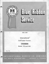
80RDM
29
21
9
20
7
6
24
8
25 31
19 26 29
30
18
1
7
12
11
10
20
6
9
2
19
13
16
5
4
17
14
15
28
3
23
28
5
16
13
17
14
15
27
22
12
12
80RDM Series
Service Manual

PARTS LIST FOR 80RDM INDEX DRIVE (STANDARD CONFIGURATION)
ITEM NO. PART NUMBER DESCRIPTION
1 .................... 55D67120001002.................... HOUSING
55C67853001002.................... HOUSING W/180SM ALT
2 .................... 55C66919014010.................... FOLLOWER WHEEL H16 FOLLOWERS
55C66918034012.................... FOLLOWER WHEEL H20 FOLLOWERS
3 .................... ------------------------- ................... CAM (SPECIFY NUMBER OF STOPS AND
INDEX TIME, CONTACT CAMCO FOR
ASSISTANCE)
4 .................... 55B66884007002 .................... SHAFT INP DE (W/O REDUCER)
55C67384007002.................... SHAFT INP DE (FOR REDUCER)
5 .................... 55B66894003002 .................... CART MACH INP OPEN
6 .................... 55C66920000000.................... RERTAINER OUTP BRG
7 .................... 86A67170000000 .................... BRG KAYDON KD045XPOK
8 .................... 55A66959000000 .................... TUBE, THRU HOLE
9 .................... 84A67143740000 .................... QUAD RING MINN-R 353-525K
84A67421740000 .................... QUAD RING VITON (#Q4353-514AD)
84C65421380000.................... OIL SEAL C/R 29540 NITRILE
84A67422410000 .................... OIL SEAL (METRIC) - VITON
10 .................. 84A67143480000 .................... QUAD RING NITRILE (FOR STATIONARY
OUTPUT ONLY)
11 .................. 55B67172018800 .................... SHIM, 0.002 THK RETAINER
55B67172028800 .................... SHIM, 0.005 THK RETAINER
55B67172038800 .................... SHIM, 0.010 THK RETAINER
12 ..................------------------------- ................... CONSULT CAMCO FOR SHIM NUMBER
13 .................. 55B67159018800 .................... SHIM INP
55B67159028800 .................... SHIM INP
55B67159038800 .................... SHIM INP
55B67159048800 .................... SHIM INP
14 .................. 86D07328090021.................... BEARING CONE LM 12749
15 .................. 86D07328090022.................... BEARING CUP LM12711
16 .................. 95A33040180000 .................... SHCS M6 X 18
17 .................. 84C65421040000.................... OIL SEAL C/R 7915 NITRILE
84C65421050000.................... METRIC OIL SEAL C/R 7916
18 .................. 84A64420660000 .................... O-RING 70MM X 3 MM NITRILE (FOR
STATIONARY OUTPUT ONLY)
19 .................. 82C33150010003.................... CAM FLWR H20
82C33150060003.................... CAM FLWR H20
20 .................. 95A51910310000 .................... S.H.C.S. M4 X 12
21 .................. 95A33040040000 .................... S.H.C.S. M5 X 12
22 .................. 95A26021210000 .................... WASHER FLAT 3/16 VLIER 6018
23 .................. 018K200 .................................. KEY 0.1875 SQ. X 2.00
24 .................. 55C66969000000.................... SHAFT STATIONARY OUTPUT (OPTIONAL)
25 .................. 89B67859009100 .................... MTG PLT 180SM ON 450RDM
13
13
80RDM Series
Service Manual

PARTS LIST FOR 80RDM CONTINUED
ITEM NO. PART NUMBER DESCRIPTION
26 95A33041120000 S.S.S. CUP PT. M4 X 8
(USED WITH H16 FOLLOWERS)
95A33041190000 .................... S.S.S. CUP PT. M5 X 8
(USED WITH H20 FOLLOWERS)
27 .................. 55A67131009000 .................... SPACER INPUT, 450RDM
28 .................. 84A64420410000 .................... O-RING 60MM X 2.5 MM NITRILE
29 .................. 5MA52057000000 ................... BORE PLUG 2.756
30 .................. 55A67134000000 .................... BORE PLUG, 3.937 BORE
31 .................. 95A33040180000 .................... SHCS M6 X 18
14
14
80RDM Series
Service Manual

1
TABLE OF CONTENTS
INTRODUCTION.................................................................................................................... 2
WARNING AND CAUTIONS.................................................................................................. 2
OIL SEAL REMOVAL............................................................................................................. 2
SPARE PARTS KIT................................................................................................................ 2
DISASSEMBLY ...................................................................................................................... 3
REMOVAL OF OUTPUT/FOLLOWER WHEEL ..................................................................... 3
INSPECTION & REMOVAL OF CAM FOLLOWERS ............................................................. 3
INPUT SHAFT/CAM REMOVAL ............................................................................................ 4
PRIOR TO REASSEMBLY..................................................................................................... 5
ASSEMBLY ........................................................................................................................... 5
ASSEMBLING INPUT SHAFT ............................................................................................... 5
ASSEMBLING OUTPUT SHAFT............................................................................................ 5
SETTING CAM....................................................................................................................... 6
HOW TO ORDER PARTS ..................................................................................................... 8
EXPLODED PARTS DRAWING............................................................................................. 9
PARTS LIST ........................................................................................................................ 10
1
Service Manual
601RDM, 902RDM, 1305RDM, 1800RDM Series

INTRODUCTION
This service manual pertains to the disassembly and assembly of CAMCO’s RDM Series Index Drives models
601RDM, 902RDM, 1305RDM, & 1800RDM.
The manual is to be used in conjunction with the General Service Manual which describes the lubrication and
general maintenance of CAMCO Index Drives.
An exploded view of your specific Index Drive is included in this manual. Also included is a complete Bill of
Materials for your convenience in identifying and ordering spare or replacement parts.
Some users of Index Drives have the facilities and trained personnel to accomplish service repair. You must
determine the extent to which intricate servicing should be done in your own facility. When in doubt, CAMCO
recommends that CAMCO trained servicemen make the repairs.
WARNINGS AND CAUTIONS
Statements in this manual preceded by the words WARNING or CAUTION and printed in italics are very
important. We recommend you take special notice of these during service or repair.
WARNING
Means there is the possibility of personal injury to yourself or others.
CAUTION
Means there is the possibility of damage to the CAMCO unit.
OIL SEAL REMOVAL
The only repair possible without disassembly of the indexer is replacement of oil seals. To remove oil seals, drill
a number of holes into the case of the seal. The seal may then be removed with a pointed tool. Be sure to
remove all metallic chips created during the drilling of removal holes. A new seal may be installed as outlined in
the “Oil Seal Installation Recommendations” section of the “General Service Manual”.
SPARE PARTS KIT
CAMCO offers a Spare Parts Kit for all CAMCO index drive models CAMCO builds. These kits include oil seals,
bearings, shims and miscellaneous haqrdware. Camfollowers are sold seperately. These are components that
will most likely require replacement during repair of your index drive. CAMCO recommends a Spare Parts Kit
be purchased and kept on hand prior to the disassembly of your CAMCO drive.
A compete list of components supplied in the Spare Parts Kit can be found in the parts list located in the rear of
this manual. The asterisk behind the item number indicates those parts supplied with the Spare Parts Kit.
See page 16 for additional spare parts information.
BEFORE STARTING
Before starting the disassembly of your CAMCO unit you should read and review the following instructions.
These provide important information on parts and procedures necessary to successfully complete your repair.
Comply with all Warnings and Cautions
.
Read the “Trouble Shooting Guide” section of your “General Service Manual” before disassembling CAMCO
units. CAMCO recommends returning defective equipment for inspection and repair whenever possible.
CAMCO uses Loc-Tite to secure all screws and setscrews, If you encounter a fastener that is difficult to
remove, apply heat to the screw and remove while still warm.
2
DISASSEMBLY
1. REMOVE ALL ACCESSORY EQUIPMENT such
as clutches, reducers, sprockets, etc. If equipped
with a CAMCO R250 Reducer see disassembly
instructions manual 0079 pertaining to this
reducer prior to removal from the unit.
2. DRAIN OIL AND FLUSH UNIT with flushing
solvent. Retain any chips or broken pieces you
may find. These may aid in diagnosis.
3. REMOVE BOTTOM COVER.
4. REMOVAL OF OUTPUT SHAFT.
A. Remove the capscrews holding the large
output bearing retaining ring.
B. Drive the two dowel pins through the
retaining ring and housing with an undersize
punch.
C. Lift the output/follower wheel from the
housing. Save the retaining ring shims for
later installation.
Fig.1 Output shaft removal
5. FOLLOWER INSPECTION.
Inspect followers for damage or radial looseness. It
should not exceed .001 inch. Do not confuse radial
looseness with axial endplay. Endplay will be from
.03” to .06” as a normal condition. If it exceeds .06
it may require replacement.
NOTE: Generally, followers are replaced as added
insurance against failure later.
Fig.2 Inspecting for radial looseness
6. FOLLOWER REMOVAL.
Followers can be removed at this stage.
A. Remove the setscrews. Apply heat to the
setscrews holding the follower studs and
remove while still warm.
B. Threaded holes have been provided in the
ends of the follower for ease of removal.
Use a slide hammer or a simple self-made
pull tool. The self-made pull tool consists of
a short piece of round tubing, large enough
to clear the follower diameter and a small
flat bar with a clearance hole large enough
to insert a capscrew of equal thread size as
the follower pull hole. Slip the tube over the
follower, place the bar over the tube and
thread a capscrew into the follower.
Tightening the capscrew will remove the
follower.
Fig.3 Follower pull tools.
3
2
Service Manual
601RDM, 902RDM, 1305RDM, 1800RDM Series

DISASSEMBLY
1. REMOVE ALL ACCESSORY EQUIPMENT such
as clutches, reducers, sprockets, etc. If equipped
with a CAMCO R250 Reducer see disassembly
instructions manual 0079 pertaining to this
reducer prior to removal from the unit.
2. DRAIN OIL AND FLUSH UNIT with flushing
solvent. Retain any chips or broken pieces you
may find. These may aid in diagnosis.
3. REMOVE BOTTOM COVER.
4. REMOVAL OF OUTPUT SHAFT.
A. Remove the capscrews holding the large
output bearing retaining ring.
B. Drive the two dowel pins through the
retaining ring and housing with an undersize
punch.
C. Lift the output/follower wheel from the
housing. Save the retaining ring shims for
later installation.
Fig.1 Output shaft removal
5. FOLLOWER INSPECTION.
Inspect followers for damage or radial looseness. It
should not exceed .001 inch. Do not confuse radial
looseness with axial endplay. Endplay will be from
.03” to .06” as a normal condition. If it exceeds .06
it may require replacement.
NOTE: Generally, followers are replaced as added
insurance against failure later.
Fig.2 Inspecting for radial looseness
6. FOLLOWER REMOVAL.
Followers can be removed at this stage.
A. Remove the setscrews. Apply heat to the
setscrews holding the follower studs and
remove while still warm.
B. Threaded holes have been provided in the
ends of the follower for ease of removal.
Use a slide hammer or a simple self-made
pull tool. The self-made pull tool consists of
a short piece of round tubing, large enough
to clear the follower diameter and a small
flat bar with a clearance hole large enough
to insert a capscrew of equal thread size as
the follower pull hole. Slip the tube over the
follower, place the bar over the tube and
thread a capscrew into the follower.
Tightening the capscrew will remove the
follower.
Fig.3 Follower pull tools.
3
3
Service Manual
601RDM, 902RDM, 1305RDM, 1800RDM Series

Fig.3A Follower pull tools in use.
7. CHECK THE FOLLOWER HOLES.
Check the follower holes for roundness.These
holes may be worn out due to overloads. The
holes should be round to within .0005 to permit
reuse of the follower wheel.
8. OUTPUT SHAFT DISASSEMBLY.
A. Turn output shaft over and tap on back side
of retaining ring, alternating from side to
side until the retaining ring is free of the
output/follower wheel.
B. Remove the main bearing from the output/
follower wheel.
1) Remove the bearing retaining capscrews
and washers.
2) From the top side of the output, place a
small aluminum bar against the inside face
of the bearing and tap with a hammer.
Alternate from side to side to prevent
cocking until the bearing is free of the
output/follower wheel.
Fig .4. Removing output bearing.
9. INPUT SHAFT / CAM REMOVAL.
NOTE: The output shaft must be removed prior
to input shaft removal.
A. Rotate the input shaft and inspect all parts
for damage or wear. Endplay in the input
shaft is not permissible.
B. Remove all input bearing cartridge
capscrews.
C. Tap on the end of the input shaft to drive the
opposite cartridge from the housing. Then
drive the shaft in the opposite direction for
removal of the other cartridge.
NOTE: Keep shims with their respective
cartridges. You will be asked to reinstall or
replace with the same shim thickness during
assembly.
D. Remove the input shaft/cam assembly from
the housing.
Fig. 5 Removing input shaft assembly
4
E. Use a wheel puller to remove the bearing
cones from the input shaft.
F. Remove the cam locknuts with a spanner
wrench. Be sure to bend the washer locking
tangs away from the nut prior to removal, if
applicable.
G. Use an arbor press to remove the cam from
the input shaft. Use caution not to damage
the parts. If an arbor press is not available
you may drive the shaft out by tapping on
the end of the shaft with a soft face.
hammer.
Fig. 6 Pressing out camshaft
10. REMOVE THE INPUT BEARING CUPS
Remove the input bearing cups from the
cartridges with a pulley puller, by prying or
by drilling and tapping for jack screws.
ASSEMBLY
PRIOR TO REASSEMBLY
Clean and deburr all parts before reassembly.
Follow tightening torque and Loc-Tite
recommendations as outlined in the “General
Service Manual”.
1. Use an arbor to press the bearing cups into the
cartridges. Coat the outside of the cup and the
bore of the cartridge with an anti-seize lubricant
prior to pressing. Fill cavity of cartridges with
bearing grease recommended in the “General
Service Manual”.
2. ASSEMBLING INPUT SHAFT.
A. Use arbor to press the cam onto the shaft.
Be sure key is installed into the shaft first.
Apply anti-sieze lubricant to shaft and bore
prior to pressing. If a heat gun is available it
is recommended that the bore of the cam be
heated prior to pressing.
B. Use a spanner wrench to install the cam
locknuts. Adjust nuts to center cam on
shaft.
Fig.7. Centering cam on shaft
C. Use an arbor to press bearing cones onto
shaft. Coat shaft and bearing bore with anti-
sieze lubricant prior to pressing. If a heat
gun is available it is recommended that the
bore of the bearing be heated prior to
pressing.
D. Install the input cartridges. Be sure to install
the same exact shims or equivalent height
as was removed in disassembly Step 9C.
E. Tighten cartridge mounting screws.
F. If endplay exists remove an equal amount of
shims from each side until there is a small
amount of drag from preloading the
bearings. In rare instances it may be
necessary to re-machine the cartridges if all
shims have been removed and endplay still
exists.
3. ASSEMBLING OUTPUT SHAFT.
A. Install the large bearing cones on the output
shaft. Coat the bore of the cone with an anti-
sieze lubricant prior to installation. Tap in
place with a hammer and aluminum bar.
Place the bar against the inner face and tap
with hammer. Alternate from side to side to
avoid binding until the bearing is fully seated
on the output/follower wheel.
5
4
Service Manual
601RDM, 902RDM, 1305RDM, 1800RDM Series
/