2
1 - SAFETY CONSIDERATIONS
Installation, servicing and maintenance of air conditioning
equipment can be hazardous due to system pressure and
electrical components. Only trained and qualied service
personnel should install, start-up or service air conditioning
equipment.
Untrained personnel can perform the basic maintenance
functions of cleaning and replacing lters. All other operations
should be performed by trained service personnel. When
working on air conditioning equipment, observe precautions in
the manual and stickers on the unit and other safety precautions
that may apply locally, regionally and nationally, as well as all
applicable laws.
Follow all safety codes. Wear safety glasses and work gloves
suitable for the work carried out.
Disconnect the unit electrically at the main switch before
carrying out any work inside the unit. All procedures that do not
require unit operation, as well as all cleaning and maintenance
operations must be done with the unit de-energised.
WARNING: Before performing service or maintenance
operations on the unit turn off the main power switch to the
unit. Electric shocks could cause serious injuries.
2 - RECEIVING THE ELECTRIC HEATER
2.1 - Inspect the shipment
Inspect the shipment to check for transport damage. If there are
signs of damage the transport managers must inspect the
component before it is installed. Immediately le a claim with
the shipping company or note the damage in the shipping
documents. The manufacturer is not responsible for damage
incurred during transport.
Check that all components listed on the shipping documents
have been supplied. If any item is missing, immediately inform
the nearest Carrier ofce and make a note on the shipping
documents. To prevent damage and/or loss keep all components
in their original packaging until they are installed by qualied
personnel.
3 – UNIT INSTALLATION
The electric heaters (accessory/option) are supplied for installa-
tion in the units and have not been factory-installed; they must be
installed as described in this manual. The manual only applies
to heaters with the ordering code ending in the letter „D“ (e.g.
X40TY04B09D (50TY/YZ 024 with 1.5 kW capacity).
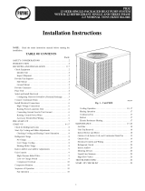
A - The electric heaters are always installed outside the unit
and are xed to the panel of the indoor fan air discharge,
as shown in Figs. 1, 2 and 3.
B - Whether the unit is installed or not, the heater must be
attached by xing it to the panel of the indoor fan outlet,
using the four threaded sheet metal screws supplied with
the heater. The electric heater is installed so that the
control box is above or below depending on the position
of the indoor fan air discharge outlet (see Figs. 2 and 3).
C - If the unit is already installed and connected to the air
discharge duct, this must be cut in accordance with the
depth of the heater so that this can be installed. Next
attach the duct to the heater.
D - The heater thermal protection devices must always be
located in the upper part, whatever the position of the
heater control box.
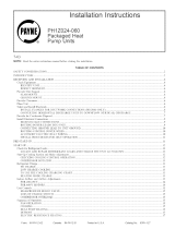
E - The heater must be xed to the unit as shown in the
following gures:
Fig. 4: View of the electric heater
Fig. 5: View of the indoor fan outlet panel
Fig. 6: View of the installation of the heater in the unit
Fig. 1 - Front view
Fig. 2 - Side view: Unit with indoor fan situated on top
of the panel
Fig. 3 - Side view: Unit with indoor fan situated below
the panel
Indoor fan air discharge panelAir intake lter
UnitElectric heater Indoor fan
Air ow
Indoor fan Electric heater
Control box
Unit
Control box
Air ow