Omron CP2E Programmable Controller User manual
- Type
- User manual

USER’S MANUAL
Cat. No. W614-E1-01
SYSMAC CP Series
CP2E-ED-
CP2E-SD-
CP2E-ND-
CP2E CPU Unit Software

Copyrights
Microsoft product screen shots reprinted with permission from Microsoft Corporation.
All rights reserved. No part of this publication may be reproduced, stored in a retrieval system, or transmitted, in
any form, or by any means, mechanical, electronic, photocopying, recording, or otherwise, without the prior
written permission of OMRON.
No patent liability is assumed with respect to the use of the information contained herein. Moreover, because
OMRON is constantly striving to improve its high-quality products, the information contained in this manual is
subject to change without notice. Every precaution has been taken in the preparation of this manual. Neverthe-
less, OMRON assumes no responsibility for errors or omissions. Neither is any liability assumed for damages
resulting from the use of the information contained in this publication.
NOTE
• Microsoft, Windows are either registered trademarks or trademarks of Microsoft Corporation in the United States
and other countries.
Other company names and product names in this document are the trademarks or registered trademarks of their
respective companies.
Trademarks


SYSMAC CP Series
CP2E-ED-
CP2E-SD-
CP2E-ND-
CP2E CPU Unit Software
User’s Manual
Produced September 2019

1
CP2E CPU Unit Software User’s Manual(W614)
Introduction
Thank you for purchasing a SYSMAC CP-series CP2E Programmable Controller.
This manual contains information required to use the CP2E. Read this manual completely and be sure
you understand the contents before attempting to use the CP2E.
This manual is intended for the following personnel, who must also have knowledge of electrical sys-
tems (an electrical engineer or the equivalent).
•Personnel in charge of installing FA systems
•Personnel in charge of designing FA systems
•Personnel in charge of managing FA systems and facilities
zCP-series CP2E CPU Units
•Essential Model CP2E-ED-
A model of CPU Unit that supports connections to Programmable Terminals and basic control
applications using instructions such as basic, movement, arithmetic, and comparison instructions.
•Standard Model CP2E-SD-
A model of CPU Unit that supports connections to inverters and servo drives.
•Network Model CP2E-ND-
A model of CPU Unit that supports Ethernet connection and enhanced positioning functions such
as 4-axis linear interpolation and pulse.
The CP Series is centered around the CP1H, CP1L, CP1E and CP2E CPU Units and is designed
with the same basic architecture as the CS and CJ Series.
Always use CP-series Expansion Units and CP-series Expansion I/O Units when expanding I/O
capacity.
Intended Audience
Applicable Products

2CP2E CPU Unit Software User's Manual(W614)
CP2E CPU Unit Manuals
Information on the CP2E CPU Units is provided in the following manuals.
Refer to the appropriate manual for the information that is required.
Mounting and
Setting Hardware
1
2
3
4
5
6
7
Wiring
Connecting
Online to the PLC
Software Setup
Creating the Program
Checking and
Debugging Operation
Maintenance and
Tr o ubleshooting
CP2E CPU Unit Hardware
User’s Manual(Cat. No. W613)
CP2E CPU Unit Software
User’s Manual(Cat. No. W614)
This
Manual
· Wiring methods for the power supply
· Wiring methods between external I/O devices
and Expansion I/O Units or Expansion Units
Connecting Cables for CX-Programmer
Support Software
Error codes and remedies if a problem occurs
Procedures for connecting the
CX-Programmer Support Software
Software setting methods for the CPU
Units (PLC Setup)
· Checking I/O wiring, setting the Auxiliary Area
settings, and performing trial operation
· Monitoring and debugging with the
CX-Programmer
· Program types and basic information
· CPU Unit operation
· Internal memory
· Built-in CPU functions
· Settings
· Names and specifications of the parts of all Units
· Basic system configuration for each CPU Unit
· Connection methods for Expansion I/O Units
and Expansion Units
CP1E/CP2E CPU Unit Instructions
Reference Manual(Cat. No. W483)
Detailed information on
programming instructions

3
CP2E CPU Unit Software User’s Manual(W614)
The CP2E CPU manuals are organized in the sections listed in the following tables. Refer to the appro-
priate section in the manuals as required.
Manual Configuration
CP2E CPU Unit Software User’s Manual (Cat. No. W614)
(This Manual)
Section Contents
Section 1 Overview This section gives an overview of the CP2E, describes its application
procedures.
Section 2 CPU Unit Memory This section describes the types of internal memory in a CP2E CPU
Unit and the data that is stored.
Section 3 CPU Unit Operation This section describes the operation of a CP2E CPU Unit.
Section 4 Programming Concepts This section provides basic information on designing ladder programs
for a CP2E CPU Unit.
Section 5 I/O Memory This section describes the types of I/O memory areas in a CP2E CPU
Unit and the details.
Section 6 I/O Allocation This section describes I/O allocation used to exchange data between
the CP2E CPU Unit and other units.
Section 7 PLC Setup This section describes the PLC Setup, which are used to perform basic
settings for a CP2E CPU Unit.
Section 8 Overview and Allocation
of Built-in Functions
This section lists the built-in functions and describes the overall applica-
tion flow and the allocation of the functions.
Section 9 Quick-response Inputs This section describes the quick-response inputs that can be used to
read signals that are shorter than the cycle time.
Section 10 Interrupts This section describes the interrupts that can be used with CP2E PLCs,
including input interrupts and scheduled interrupts.
Section 11 High-speed Counters This section describes the high-speed counter inputs, high-speed
counter interrupts, and the frequency measurement function.
Section 12 Pulse Outputs This section describes positioning functions such as trapezoidal control,
jogging, and origin searches.
Section 13 PWM Outputs This section describes the variable-duty-factor pulse (PWM) outputs.
Section 14 Serial Communications This section describes communications with Programmable Terminals
(PTs) without using communications programming, no-protocol commu-
nications with general components, and connections with a Modbus-
RTU Easy Master, Serial PLC Link, host computer and Modbus-RTU
Slave.
Section 15 Ethernet This section gives an outline of the built-in Ethernet function, explains its
specification and how to make the settings required for operation.
Section 16 Other Functions This section describes PID temperature control, clock functions, DM
backup functions, security functions.
Section 17 Analog Option Board This section describes an overview of the Analog Option Board,
describes its installation and setting methods, memory allocations, star-
tup operation, refresh time, troubleshooting and how to use the Analog
Option Board.
Section 18 Operating the Program-
ming Device
This section describes basic functions of the CX-Programmer, such as
using the CX-Programmer to write ladder programs to control the CP2E
CPU Unit, to transfer the programs to the CP2E CPU Unit, and to debug
the programs.
Appendices The appendices provide lists of programming instructions, the Auxiliary
Area, cycle time response performance, PLC performance at power
interruption, memory map and Ethernet functions.

4CP2E CPU Unit Software User's Manual(W614)
CP2E CPU Unit Hardware User’s Manual (Cat. No. W613)
Section Contents
Section 1 Overview and Specifica-
tions
This section gives an overview of the CP2E, describes its features, and
provides its specifications.
Section 2 Basic System Configura-
tion and Devices
This section describes the basic system configuration and unit models
of the CP2E.
Section 3 Part Names and Functions This section describes the part names and functions of the CPU Unit,
Expansion I/O Units, and Expansion Units in a CP2E PLC.
Section 4 Programming Device This section describes the features of the CX-Programmer used for pro-
gramming and debugging PLCs, as well as how to connect the PLC with
the Programming Device by USB, Ethernet and serial port.
Section 5 Installation and Wiring This section describes how to install and wire CP2E Units.
Section 6 Troubleshooting This section describes how to troubleshoot problems that may occur
with a CP2E PLC, including the error indications provided by the CP2E
Units.
Section 7 Maintenance and Inspec-
tion
This section describes periodic inspections, the service life of the Bat-
tery, and how to replace the Battery.
Section 8 Using Expansion Units
and Expansion I/O Units
This section describes application methods for Expansion Units.
Appendices The appendices provide information on dimensions, wiring diagrams,
and wiring serial communications, network installation for the CP2E and
comparison between CP1E and CP2E.
CP1E/CP2E CPU Unit Instructions Reference Manual (Cat. No. W483)
Section Contents
Section 1 Summary of Instructions This section provides a summary of instructions used with a
CP1E/CP2E CPU Unit.
Section 2 Instruction This section describes the functions, operands and sample programs of
the instructions that are supported by a CP1E/CP2E CPU Unit.
Section 3 Instruction Execution
Times and Number of Steps
This section provides the execution times for all instructions used with a
CP1E/CP2E CPU Unit.
Section 4 Monitoring and Comput-
ing the Cycle Time
This section describes how to monitor and calculate the cycle time of a
CP1E/CP2E CPU Unit that can be used in the programs.
Appendices The appendices provide a list of instructions by Mnemonic and ASCII
code table for the CP1E/CP2E CPU Unit.

5
CP2E CPU Unit Software User’s Manual(W614)
Manual Structure
The following page structure and icons are used in this manual.
Special information in this manual is classified as follows:
Page Structure and Icons
Special Information
5 - 3
5 Installation and wiring
CP2E CPU Unit Hardware User’s Manual(W613)
5
5-2 Installation
5-2-1 Installation Location
DIN Track Installation
1
2
Release
DIN Track mounting pins
3
DIN Track
DIN Track mounting pins
Precautions for Correct Use
Tighten terminal block screws and cable screws to the following torques.
M4: 1.2 N·m
M3: 0.5 N·m
Use a screwdriver to pull down the DIN Track mounting pins from the back of the Units to release
them, and mount the Units to the DIN Track.
Fit the back of the Units onto the DIN Track by catching the top of the Units on the Track and then
pressing in at the bottom of the Units, as shown below.
Press in all of the DIN Track mounting pins to securely lock the Units in place.
5-2 Installation 5-2-1 Installation Location
Level 1 heading
Level 2 heading
Level 3 heading
Level 2 heading
Step in a procedure
Manual name
Special Information
(See below.)
Level 3 heading
Page tab
Gives the current
headings.
Indicates a step in a
procedure.
Gives the number
of the section.
This illustration is provided only as a sample and may not literally appear in this manual.
Icons are used to indicate
precautions and
additional information.
Precautions for Safe Use
Precautions on what to do and what not to do to ensure using the product safely.
Precautions for Correct Use
Precautions on what to do and what not to do to ensure proper operation and performance.
Additional Information
Additional information to increase understanding or make operation easier.

6CP2E CPU Unit Software User's Manual(W614)
Terminology and Notation
Term Description
E-type CPU Unit An essential model of CPU Unit that supports connections to Programmable Terminals
and basic control applications using instructions such as basic, movement, arithmetic,
and comparison instructions.
Essential models of CPU Units are called “E-type CPU Units” or “E14/20 CPU Units”
in this manual.
The models of E-type CPU Units are shown below.
CP2E-ED-
S-type CPU Unit A standard model of CPU Unit that supports connections to inverters and servo drives.
Standard models of CPU Units are called “S-type CPU Units” or “S30/40/60 CPU
Units” in this manual.
The models of S-type CPU Units are shown below.
CP2E-SD-
N-type CPU Unit A network model of CPU Unit that supports Ethernet connection and enhanced position-
ing functions such as 4-axis linear interpolation and pulse.
Network models of CPU Units are called “N-type CPU Units” or “N30/40/60 CPU
Units” in this manual.
The models of N-type CPU Units are shown below.
CP2E-ND-
CX-One
CX-Programmer
A programming device that applies for programming and debugging PLCs.
CP2E CPU Units are supported by CX-One version 4.51 or higher and CX-Programmer
version 9.72 or higher.

7
CP2E CPU Unit Software User’s Manual(W614)
Sections in this Manual
111
2
3
4
5
6
7
8
9
12
13
Overview
Quick-response
InputsAppendices
Interrupts
High-speed Counters
Pulse Outputs
PWM Outputs
Internal Memory
in the CPU Unit
CPU Unit Operation
Understanding
Programming
I/O Memory
I/O Allocation
PLC Setup
10
14
15
Serial
Communications
Ethernet
16 Other Functions
17 Analog
Option Board
18Programming
Device Operations
A
Overview of Built-in
Functions and
Allocations
1 11
2 12
313
4
5
6
7
8
9
10
14
15
16
17
18
APP

8CP2E CPU Unit Software User’s Manual(W614)
CONTENTS
Introduction ...............................................................................................................1
CP2E CPU Unit Manuals...........................................................................................2
Manual Structure .......................................................................................................5
Terms and Conditions Agreement.........................................................................15
Safety Precautions..................................................................................................17
Precautions for Safe Use........................................................................................19
Regulations and Standards....................................................................................21
Software Licenses and Copyrights .......................................................................22
Related Manuals......................................................................................................23
Section 1 Overview
1-1 CP2E Overview ........................................................................................................................ 1-2
1-1-1 Overview of Features .................................................................................................................. 1-2
1-2 Basic Operating Procedure ....................................................................................................1-3
Section 2 Internal Memory in the CPU Unit
2-1 Internal Memory in the CPU Unit............................................................................................ 2-2
2-1-1 CPU Unit Memory Backup Structure ..........................................................................................2-2
2-1-2 Memory Areas and Stored Data ................................................................................................. 2-3
2-1-3Transferring Data from a Programming Device ........................................................................... 2-4
2-1-4 Backup ........................................................................................................................................ 2-4
Section 3 CPU Unit Operation
3-1 CPU Unit Operation ................................................................................................................. 3-2
3-1-1 Overview of CPU Unit Operation ................................................................................................ 3-2
3-1-2 CPU Unit Operating Modes......................................................................................................... 3-3
3-2 Backing Up Memory ................................................................................................................ 3-5
3-2-1 CPU Unit Memory Configuration................................................................................................. 3-5
3-2-2 Backing Up Ladder Programs and Parameter Area.................................................................... 3-6
3-2-3I/O Memory Backup .................................................................................................................... 3-6
3-2-4 Initializing I/O Memory at Startup................................................................................................ 3-7
Section 4 Understanding Programming
4-1 Programming ........................................................................................................................... 4-2
4-1-1 User Programs ............................................................................................................................ 4-2
4-1-2 Program Capacity ....................................................................................................................... 4-3
4-1-3Basics of Programming ............................................................................................................... 4-3
4-2 Tasks, Sections, and Symbols ............................................................................................... 4-6
4-2-1 Overview of Tasks ....................................................................................................................... 4-6
4-2-2 Overview of Sections .................................................................................................................. 4-6
4-2-3Overview of Symbols .................................................................................................................. 4-6

9
CP2E CPU Unit Software User’s Manual(W614)
4-3 Function Blocks....................................................................................................................... 4-8
4-3-1 Overview of Function Blocks....................................................................................................... 4-8
4-3-2 Advantages of Function Blocks................................................................................................... 4-8
4-3-3Function Block Specifications ...................................................................................................4-10
4-3-4 ST Language............................................................................................................................. 4-12
4-4 Programming Instructions.................................................................................................... 4-14
4-4-1 Basic Understanding of Instructions ......................................................................................... 4-14
4-4-2 Operands .................................................................................................................................. 4-15
4-4-3Instruction Variations................................................................................................................. 4-16
4-4-4 Execution Conditions ................................................................................................................ 4-16
4-4-5 Specifying Data in Operands .................................................................................................... 4-18
4-4-6 Data Formats ............................................................................................................................ 4-20
4-4-7 I/O Refresh Timing.................................................................................................................... 4-22
4-5 Constants ............................................................................................................................... 4-23
4-6 Index Registers ...................................................................................................................... 4-26
4-6-1 What are Index Registers?........................................................................................................ 4-26
4-6-2 Using Index Registers ............................................................................................................... 4-26
4-6-3Monitoring Index Registers ....................................................................................................... 4-30
4-7 Specifying Offsets for Addresses ........................................................................................ 4-32
4-7-1 Overview ................................................................................................................................... 4-32
4-7-2 Application Examples for Address Offsets ................................................................................ 4-34
4-8 Ladder Programming Precautions...................................................................................... 4-35
4-8-1 Special Program Sections......................................................................................................... 4-35
Section 5 I/O Memory
5-1 Overview of I/O Memory Areas............................................................................................... 5-2
5-1-1 I/O Memory Areas....................................................................................................................... 5-2
5-1-2 I/O Memory Area Address Notation ............................................................................................ 5-5
5-1-3I/O Memory Areas....................................................................................................................... 5-6
5-2 I/O Bits ...................................................................................................................................... 5-7
5-3 Work Area (W) .......................................................................................................................... 5-8
5-4 Holding Area (H) ...................................................................................................................... 5-9
5-5 Data Memory Area (D) ........................................................................................................... 5-11
5-6 Timer Area (T) ........................................................................................................................ 5-13
5-7 Counter Area (C) .................................................................................................................... 5-15
5-8 Index Registers (IR) ............................................................................................................... 5-17
5-9 Data Registers (DR) ............................................................................................................... 5-21
5-10 Auxiliary Area (A)................................................................................................................... 5-23
5-11 Condition Flags...................................................................................................................... 5-25
5-12 Clock Pulses .......................................................................................................................... 5-27
Section 6 I/O Allocation
6-1 Allocation of Input Bits and Output Bits ............................................................................... 6-2
6-1-1 I/O Allocation............................................................................................................................... 6-2
6-1-2 I/O Allocation Concepts............................................................................................................... 6-3
6-1-3Allocations on the CPU Unit........................................................................................................ 6-3
6-1-4 Allocations to Expansion Units and Expansion I/O Units ............................................................ 6-4
Section 7 PLC Setup
7-1 Overview of the PLC Setup..................................................................................................... 7-2
7-2 PLC Setup Settings ................................................................................................................. 7-3
7-2-1 Startup and CPU Unit Settings ................................................................................................... 7-3
7-2-2 Timing and Interrupt Settings...................................................................................................... 7-4

10 CP2E CPU Unit Software User’s Manual(W614)
7-2-3Input Constants Settings............................................................................................................. 7-4
7-2-4 Serial Option Port 1/Built-in RS-232C Port ................................................................................. 7-5
7-2-5 Serial Option Port 2/Built-in RS-485 Port....................................................................................7-9
7-2-6 Serial Option Port 1 (EX) .......................................................................................................... 7-13
7-2-7 Built-in Inputs ............................................................................................................................ 7-16
7-2-8Pulse Output 0 Settings ............................................................................................................ 7-18
7-2-9 Pulse Output 1 Settings ............................................................................................................ 7-19
7-2-10 Pulse Output 2 Settings ............................................................................................................ 7-21
7-2-11 Pulse Output 3 Settings ............................................................................................................7-22
7-2-12 Built-in Ethernet Settings .......................................................................................................... 7-24
Section 8 Overview of Built-in Functions and Allocations
8-1 Built-in Functions .................................................................................................................... 8-2
8-2 Overall Procedure for Using CP2E Built-in Functions ......................................................... 8-3
8-3 Terminal Allocations for Built-in Functions .......................................................................... 8-4
8-3-1 Specifying the Functions to Use.................................................................................................. 8-4
8-3-2 Selecting Functions in the PLC Setup......................................................................................... 8-4
8-3-3Allocating Built-in Input Terminals ............................................................................................... 8-6
8-3-4 Allocating Built-in Output Temrinals ............................................................................................ 8-8
Section 9 Quick-response Inputs
9-1 Quick-response Inputs............................................................................................................ 9-2
9-1-1 Overview ..................................................................................................................................... 9-2
9-1-2 Flow of Operation........................................................................................................................ 9-3
Section 10 Interrupts
10-1 Interrupts ................................................................................................................................ 10-2
10-1-1 Overview ................................................................................................................................... 10-2
10-2 Input Interrupts ...................................................................................................................... 10-3
10-2-1 Overview ................................................................................................................................... 10-3
10-2-2 Flow of Operation...................................................................................................................... 10-4
10-2-3Application Example.................................................................................................................. 10-8
10-3 Scheduled Interrupts........................................................................................................... 10-10
10-3-1 Overview ................................................................................................................................. 10-10
10-3-2 Flow of Operation.................................................................................................................... 10-11
10-4 Precautions for Using Interrupts........................................................................................ 10-13
10-4-1 Interrupt Task Priority and Order of Execution ........................................................................ 10-13
10-4-2 Related Auxiliary Area Words and Bits ................................................................................... 10-13
10-4-3Duplicate Processing in each Task .........................................................................................10-13
Section 11 High-speed Counters
11-1 Overview................................................................................................................................. 11-2
11-1-1 Overview ................................................................................................................................... 11-2
11-1-2 Flow of Operation...................................................................................................................... 11-3
11-1-3Specifications ............................................................................................................................ 11-7
11-2 High-speed Counter Inputs................................................................................................... 11-8
11-2-1 Pulse Input Methods Settings ................................................................................................... 11-8
11-2-2 Counting Ranges Settings ...................................................................................................... 11-10
11-2-3Reset Methods........................................................................................................................ 11-11
11-2-4 Reading the Present Value ..................................................................................................... 11-12
11-2-5 Frequency Measurement ........................................................................................................ 11-13
11-3 High-speed Counter Interrupts........................................................................................... 11-14
11-3-1 Overview ................................................................................................................................. 11-14
11-3-2 Present Value Comparison .....................................................................................................11-17
11-3-3High-speed Counter Interrupt Instruction................................................................................ 11-20
11-4 Related Auxiliary Area Bits and Words ............................................................................. 11-25

11
CP2E CPU Unit Software User’s Manual(W614)
11-5 Application Example .......................................................................................................... 11-26
Section 12 Pulse Outputs
12-1 Overview................................................................................................................................. 12-3
12-1-1 Overview................................................................................................................................... 12-3
12-1-2 Flow of Operation ..................................................................................................................... 12-4
12-1-3Specifications.......................................................................................................................... 12-15
12-2 Positioning Control ............................................................................................................. 12-16
12-2-1 Positioning Control Configuration ........................................................................................... 12-16
12-2-2 Relative Positioning and Absolute Positioning ........................................................................ 12-16
12-2-3Application Example ............................................................................................................... 12-18
12-3 Jogging................................................................................................................................. 12-20
12-3-1 High-speed Jogging................................................................................................................ 12-20
12-3-2 Low-speed Jogging................................................................................................................. 12-20
12-3-3Application Example ............................................................................................................... 12-20
12-4 Implementing Interrupt Feeding......................................................................................... 12-23
12-4-1 Interrupt Feeding .................................................................................................................... 12-23
12-4-2 Flow of Operation ................................................................................................................... 12-23
12-4-3Application Example ............................................................................................................... 12-24
12-5 Positioning Linear Interpolation......................................................................................... 12-26
12-5-1 Positioning Linear Interpolation .............................................................................................. 12-26
12-5-2 Positioning Linear Interpolation Configuration ........................................................................ 12-27
12-5-3Application Example ............................................................................................................... 12-28
12-6 Defining Origin Position...................................................................................................... 12-30
12-6-1 Origin Searches...................................................................................................................... 12-30
12-6-2 Flow of Operation ................................................................................................................... 12-31
12-6-3Settings in PLC Setup............................................................................................................. 12-31
12-6-4 Origin Search Instructions ...................................................................................................... 12-34
12-6-5 Origin Search Operations ....................................................................................................... 12-35
12-6-6 Origin Return .......................................................................................................................... 12-42
12-6-7 Changing the Present Value of the Pulse Output ................................................................... 12-43
12-7 Reading the Pulse Output Present Value .......................................................................... 12-44
12-8 Related Auxiliary Area Flags .............................................................................................. 12-45
12-9 Application Examples ......................................................................................................... 12-46
12-9-1 Vertically Conveying PCBs (Multiple Progressive Positioning) ............................................... 12-46
12-9-2 Feeding Wrapping Material: Interrupt Feeding ....................................................................... 12-51
12-9-3Palletize: Two-axis Multipoint Positioning................................................................................ 12-53
12-10Precautions when Using Pulse Outputs ........................................................................... 12-59
12-11Pulse Output Pattern........................................................................................................... 12-64
12-11-1 Speed Control (Continuous Mode) ......................................................................................... 12-64
12-11-2 Positioning Control (Independent Mode) ................................................................................ 12-66
Section 13 PWM Outputs
13-1 PWM Outputs (Variable-duty-factor Pulse Outputs)........................................................... 13-2
13-1-1 Flow of Operation ..................................................................................................................... 13-4
13-1-2 Ladder Program Example......................................................................................................... 13-4
Section 14 Serial Communications
14-1 Serial Communications......................................................................................................... 14-3
14-1-1 Types of CPU Units and Serial Ports ........................................................................................ 14-3
14-1-2 Overview of Serial Communications......................................................................................... 14-5
14-2 Program-free Communications with Programmable Terminals ........................................ 14-7
14-2-1 Overview................................................................................................................................... 14-7
14-2-2 Flow of Connection ................................................................................................................... 14-8
14-2-3PLC Setup and PT System Settings......................................................................................... 14-8

12 CP2E CPU Unit Software User’s Manual(W614)
14-3 No-protocol Communications with General Components............................................... 14-10
14-3-1 Overview ................................................................................................................................. 14-10
14-3-2 Flow of Operation.................................................................................................................... 14-11
14-3-3PLC Setup............................................................................................................................... 14-11
14-3-4 Related Auxiliary Area Bits and Words ................................................................................... 14-12
14-4 Modbus-RTU Easy Master Function .................................................................................. 14-14
14-4-1 Overview ................................................................................................................................. 14-14
14-4-2 Flow of Operation.................................................................................................................... 14-14
14-4-3Setting and Word Allocation.................................................................................................... 14-15
14-4-4 Programming Examples.......................................................................................................... 14-18
14-5 Serial PLC Links .................................................................................................................. 14-27
14-5-1 Overview ................................................................................................................................. 14-27
14-5-2 Flow of Operation.................................................................................................................... 14-28
14-5-3PLC Setup............................................................................................................................... 14-28
14-5-4 Operating Specifications ......................................................................................................... 14-30
14-5-5 Example Application................................................................................................................ 14-37
14-6 Connecting the Host Computer ......................................................................................... 14-39
14-6-1 Overview ................................................................................................................................. 14-39
14-6-2 Flow of Operation.................................................................................................................... 14-39
14-6-3Command/response Format and List of Commands ..............................................................14-40
14-6-4 Restrictions on the Usage of Host Link................................................................................... 14-41
14-7 Modbus-RTU Slave Function .............................................................................................. 14-42
14-7-1 Overview ................................................................................................................................. 14-42
14-7-2 Flow of Operation.................................................................................................................... 14-43
14-7-3PLC Setup............................................................................................................................... 14-43
14-7-4 Operation Specifications ......................................................................................................... 14-44
14-7-5 Command and Response Details ........................................................................................... 14-45
14-7-6 Related special auxiliary relay................................................................................................. 14-51
14-8 Precautions on the usage of RS-485 ................................................................................. 14-52
Section 15 Ethernet
15-1 System Configuration and Features.................................................................................... 15-3
15-1-1 Connecting the CX-Programmer to PLCs Online via Ethernet ................................................. 15-4
15-1-2 Exchanging Data between OMRON PLCs using Ethernet ....................................................... 15-5
15-1-3Creating an Original Communications Procedure Using TCP/IP(UDP/IP) for the Host
Application or Communicating with PLCs from Another Manufacturer .....................................15-6
15-1-4 Automatically Adjusting the PLC’s Internal Clock at Regular Intervals ..................................... 15-6
15-2 Specifications ........................................................................................................................ 15-7
15-2-1 General Specifications (Ethernet) ............................................................................................. 15-7
15-2-2 Comparison with Previous Models (Ethernet Related) ............................................................. 15-8
15-3 Basic Setting for Ethernet................................................................................................... 15-10
15-3-1 Overview of Startup Procedure............................................................................................... 15-10
15-3-2 PLC Setup Procedure ............................................................................................................. 15-11
15-3-3Basic Settings ......................................................................................................................... 15-13
15-3-4 Communications Test.............................................................................................................. 15-15
15-4 FINS Communications ........................................................................................................ 15-16
15-4-1 FINS Communications Service Specifications........................................................................15-16
15-4-2 FINS Communications Service ............................................................................................... 15-17
15-4-3Procedure for Using FINS/UDP, FINS/TCP............................................................................. 15-17
15-4-4 PLC Setup for FINS/UDP and FINS/TCP Applications .......................................................... 15-18
15-4-5 Auxiliary Area Allocations........................................................................................................ 15-22
15-4-6 New FINS Commands ............................................................................................................ 15-22
15-4-7 CMND/SEND/RECV Instructions............................................................................................ 15-34
15-4-8Restrictions When Using FINS Communication Services....................................................... 15-35
15-5 Socket Services ................................................................................................................... 15-36
15-5-1 Overview of Socket Service .................................................................................................... 15-36
15-5-2 Procedure for Using Socket Service Functions....................................................................... 15-36
15-5-3Socket Services and Socket Status ........................................................................................15-37
15-5-4 PLC Setup for Socket Services.............................................................................................. 15-38
15-5-5 Auxiliary Area Allocations........................................................................................................ 15-39
15-5-6 Data Memory Area Allocations ............................................................................................... 15-42
15-5-7 Socket/TCP Programming Example........................................................................................ 15-50

13
CP2E CPU Unit Software User’s Manual(W614)
15-6 Automatic Clock Adjustment and Specifying Servers by Host Name ............................ 15-54
15-6-1 Automatic Clock Adjustment Function .................................................................................... 15-54
15-6-2 Specifying Servers by Host Name.......................................................................................... 15-54
15-6-3Procedure for Using the Automatic Clock Adjustment Function ............................................. 15-55
15-6-4 PLC Setup for DNS and Automatic clock Adjustment............................................................. 15-55
15-6-5 Auxiliary Area Allocations ....................................................................................................... 15-58
15-7 Status Allocations of Bulit-in Ethernet Port...................................................................... 15-59
Section 16 Other Functions
16-1 PID Temperature Control ...................................................................................................... 16-2
16-1-1 Overview................................................................................................................................... 16-2
16-1-2 Flow of Operation ..................................................................................................................... 16-3
16-1-3Application Example ................................................................................................................. 16-4
16-2 Clock....................................................................................................................................... 16-7
16-3 DM Backup Function ............................................................................................................. 16-9
16-3-1 Backing Up and Restoring DM Area Data ................................................................................ 16-9
16-3-2 Procedure ............................................................................................................................... 16-11
16-4 Security Functions .............................................................................................................. 16-13
16-4-1 Ladder Program Read Protection ........................................................................................... 16-13
16-4-2 Protecting Program Execution Using the Lot Number ............................................................ 16-15
Section 17 Analog Input/Output Option Board
17-1 General Specifications.......................................................................................................... 17-2
17-2 Part Names............................................................................................................................. 17-3
17-3 Installation and Setting ......................................................................................................... 17-4
17-3-1 Installation................................................................................................................................. 17-4
17-3-2 Setting ...................................................................................................................................... 17-5
17-3-3Removing.................................................................................................................................. 17-5
17-4 Memory Allocation ................................................................................................................ 17-6
17-4-1 CIO Area Allocation .................................................................................................................. 17-6
17-4-2 Auxiliary Area Allocation ........................................................................................................... 17-6
17-5 Analog Input Option Board...................................................................................................17-8
17-5-1 Main Specifications................................................................................................................... 17-8
17-5-2 Analog Input Signal Ranges ..................................................................................................... 17-8
17-5-3Wiring ....................................................................................................................................... 17-9
17-6 Analog Output Option Board.............................................................................................. 17-12
17-6-1 Main Specifications................................................................................................................. 17-12
17-6-2 Analog Output Signal Ranges ................................................................................................ 17-12
17-6-3Wiring ..................................................................................................................................... 17-13
17-7 Analog I/O Option Board..................................................................................................... 17-16
17-7-1 Main Specifications................................................................................................................. 17-16
17-7-2 Analog I/O Signal Ranges ...................................................................................................... 17-17
17-7-3Wiring ..................................................................................................................................... 17-19
17-8 Startup Operation ................................................................................................................ 17-22
17-9 Analog Option Board Refresh Time................................................................................... 17-23
17-10Trouble Shooting ................................................................................................................. 17-24
17-11The Use of Analog Option Board ....................................................................................... 17-25
17-11-1 Procedure ............................................................................................................................... 17-25
17-11-2 Program Example ................................................................................................................... 17-26
Section 18 Programming Device Operations
18-1 Programming Devices Usable with the CP2E ..................................................................... 18-2
18-2 Overview of CX-Programmer................................................................................................ 18-3
18-2-1 CX-Programmer........................................................................................................................ 18-3
18-2-2 CX-Programmer Flow from Startup to Operation ..................................................................... 18-3

14 CP2E CPU Unit Software User’s Manual(W614)
18-2-3Help........................................................................................................................................... 18-6
18-3 Creating a Ladder Program .................................................................................................. 18-7
18-3-1 Inputting a Ladder Program ...................................................................................................... 18-7
18-3-2 Saving and Reading Ladder Programs ................................................................................... 18-14
18-3-3Editing Ladder Programs ........................................................................................................ 18-16
18-4 Connecting Online to the CP2E and Transferring the Program ...................................... 18-18
18-4-1 Connecting Online................................................................................................................... 18-18
18-4-2 Changing Operating Modes ....................................................................................................18-19
18-4-3Transferring a Ladder Program and the PLC Setup................................................................ 18-20
18-4-4 Starting Operation................................................................................................................... 18-21
18-5 Online Monitoring and Debugging..................................................................................... 18-23
18-5-1 Monitoring Status .................................................................................................................... 18-23
18-5-2 Force-set/Reset Bits................................................................................................................ 18-25
18-5-3Online Editing.......................................................................................................................... 18-26
Section A Appendices
A-1 Instruction Functions ..............................................................................................................A-2
A-1-1 Sequence Input Instructions .......................................................................................................A-2
A-1-2 Sequence Output Instructions.....................................................................................................A-3
A-1-3Sequence Control Instructions....................................................................................................A-5
A-1-4 Timer and Counter Instructions...................................................................................................A-7
A-1-5 Comparison Instructions ...........................................................................................................A-10
A-1-6 Data Movement Instructions .....................................................................................................A-12
A-1-7 Data Shift Instructions...............................................................................................................A-15
A-1-8Increment/Decrement Instructions ............................................................................................A-18
A-1-9 Symbol Math Instructions..........................................................................................................A-19
A-1-10 Conversion Instructions.............................................................................................................A-24
A-1-11 Logic Instructions ......................................................................................................................A-28
A-1-12 Special Math Instructions..........................................................................................................A-29
A-1-13Floating-point Math Instructions................................................................................................A-29
A-1-14 Table Data Processing Instructions...........................................................................................A-32
A-1-15 Data Control Instructions ..........................................................................................................A-33
A-1-16 Subroutine Instructions .............................................................................................................A-37
A-1-17 Interrupt Control Instructions.....................................................................................................A-38
A-1-18High-speed Counter/Pulse Output Instructions.........................................................................A-39
A-1-19 Step Instructions .......................................................................................................................A-50
A-1-20 Basic I/O Unit Instructions.........................................................................................................A-50
A-1-21 Serial Communications Instructions..........................................................................................A-54
A-1-22 Network Instructions .................................................................................................................A-55
A-1-23Clock Instructions......................................................................................................................A-56
A-1-24 Failure Diagnosis Instructions ...................................................................................................A-57
A-1-25 Other Instructions......................................................................................................................A-57
A-2 Auxiliary Area Allocations by Address................................................................................A-58
A-2-1 Read-only Words ......................................................................................................................A-58
A-2-2 Read/Write Words.....................................................................................................................A-82
A-3 Response Performance.........................................................................................................A-99
A-3-1 I/O Response Time ...................................................................................................................A-99
A-3-2 Interrupt Response Time ........................................................................................................A-101
A-3-3Serial PLC Link Response Performance.................................................................................A-102
A-3-4 Pulse Output Start Time..........................................................................................................A-103
A-3-5 Pulse Output Change Response Time....................................................................................A-103
A-4 PLC Operation for Power Interruptions .............................................................................A-104
A-5 Memory Map ........................................................................................................................A-107
A-6 Ethernet Functions..............................................................................................................A-109
A-6-1 TCP Status Transitions............................................................................................................A-109
A-6-2 Ethernet Network Parameters.................................................................................................A-110
A-6-3Buffer Configuration ................................................................................................................A-110
Index ......................................................................................................................................... 1-1
Revision History ......................................................................................................... Revision-1

15
CP2E CPU Unit Software User’s Manual(W614)
Terms and Conditions Agreement
zExclusive Warranty
Omron’s exclusive warranty is that the Products will be free from defects in materials and workman-
ship for a period of twelve months from the date of sale by Omron (or such other period expressed in
writing by Omron). Omron disclaims all other warranties, express or implied.
zLimitations
OMRON MAKES NO WARRANTY OR REPRESENTATION, EXPRESS OR IMPLIED, ABOUT
NON-INFRINGEMENT, MERCHANTABILITY OR FITNESS FOR A PARTICULAR PURPOSE OF
THE PRODUCTS. BUYER ACKNOWLEDGES THAT IT ALONE HAS DETERMINED THAT THE
PRODUCTS WILL SUITABLY MEET THE REQUIREMENTS OF THEIR INTENDED USE.
Omron further disclaims all warranties and responsibility of any type for claims or expenses based
on infringement by the Products or otherwise of any intellectual property right.
zBuyer Remedy
Omron’s sole obligation hereunder shall be, at Omron’s election, to (i) replace (in the form originally
shipped with Buyer responsible for labor charges for removal or replacement thereof) the non-com-
plying Product, (ii) repair the non-complying Product, or (iii) repay or credit Buyer an amount equal
to the purchase price of the non-complying Product; provided that in no event shall Omron be
responsible for warranty, repair, indemnity or any other claims or expenses regarding the Products
unless Omron’s analysis confirms that the Products were properly handled, stored, installed and
maintained and not subject to contamination, abuse, misuse or inappropriate modification. Return of
any Products by Buyer must be approved in writing by Omron before shipment. Omron Companies
shall not be liable for the suitability or unsuitability or the results from the use of Products in combi-
nation with any electrical or electronic components, circuits, system assemblies or any other materi-
als or substances or environments. Any advice, recommendations or information given orally or in
writing, are not to be construed as an amendment or addition to the above warranty.
See http://www.omron.com/global/ or contact your Omron representative for published information.
OMRON COMPANIES SHALL NOT BE LIABLE FOR SPECIAL, INDIRECT, INCIDENTAL, OR CON-
SEQUENTIAL DAMAGES, LOSS OF PROFITS OR PRODUCTION OR COMMERCIAL LOSS IN ANY
WAY CONNECTED WITH THE PRODUCTS, WHETHER SUCH CLAIM IS BASED IN CONTRACT,
WARRANTY, NEGLIGENCE OR STRICT LIABILITY.
Further, in no event shall liability of Omron Companies exceed the individual price of the Product on
which liability is asserted.
Warranty, Limitations of Liability
Warranties
Limitation on Liability; Etc

16 CP2E CPU Unit Software User’s Manual(W614)
Omron Companies shall not be responsible for conformity with any standards, codes or regulations
which apply to the combination of the Product in the Buyer’s application or use of the Product. At
Buyer’s request, Omron will provide applicable third party certification documents identifying ratings
and limitations of use which apply to the Product. This information by itself is not sufficient for a com-
plete determination of the suitability of the Product in combination with the end product, machine, sys-
tem, or other application or use. Buyer shall be solely responsible for determining appropriateness of
the particular Product with respect to Buyer’s application, product or system. Buyer shall take applica-
tion responsibility in all cases.
NEVER USE THE PRODUCT FOR AN APPLICATION INVOLVING SERIOUS RISK TO LIFE OR
PROPERTY OR IN LARGE QUANTITIES WITHOUT ENSURING THAT THE SYSTEM AS A WHOLE
HAS BEEN DESIGNED TO ADDRESS THE RISKS, AND THAT THE OMRON PRODUCT(S) IS
PROPERLY RATED AND INSTALLED FOR THE INTENDED USE WITHIN THE OVERALL EQUIP-
MENT OR SYSTEM.
Omron Companies shall not be responsible for the user’s programming of a programmable Product, or
any consequence thereof.
Data presented in Omron Company websites, catalogs and other materials is provided as a guide for
the user in determining suitability and does not constitute a warranty. It may represent the result of
Omron’s test conditions, and the user must correlate it to actual application requirements. Actual perfor-
mance is subject to the Omron’s Warranty and Limitations of Liability.
Product specifications and accessories may be changed at any time based on improvements and other
reasons. It is our practice to change part numbers when published ratings or features are changed, or
when significant construction changes are made. However, some specifications of the Product may be
changed without any notice. When in doubt, special part numbers may be assigned to fix or establish
key specifications for your application. Please consult with your Omron’s representative at any time to
confirm actual specifications of purchased Product.
Information presented by Omron Companies has been checked and is believed to be accurate; how-
ever, no responsibility is assumed for clerical, typographical or proofreading errors or omissions.
Application Considerations
Suitability of Use
Programmable Products
Disclaimers
Performance Data
Change in Specifications
Errors and Omissions
Page is loading ...
Page is loading ...
Page is loading ...
Page is loading ...
Page is loading ...
Page is loading ...
Page is loading ...
Page is loading ...
Page is loading ...
Page is loading ...
Page is loading ...
Page is loading ...
Page is loading ...
Page is loading ...
Page is loading ...
Page is loading ...
Page is loading ...
Page is loading ...
Page is loading ...
Page is loading ...
Page is loading ...
Page is loading ...
Page is loading ...
Page is loading ...
Page is loading ...
Page is loading ...
Page is loading ...
Page is loading ...
Page is loading ...
Page is loading ...
Page is loading ...
Page is loading ...
Page is loading ...
Page is loading ...
Page is loading ...
Page is loading ...
Page is loading ...
Page is loading ...
Page is loading ...
Page is loading ...
Page is loading ...
Page is loading ...
Page is loading ...
Page is loading ...
Page is loading ...
Page is loading ...
Page is loading ...
Page is loading ...
Page is loading ...
Page is loading ...
Page is loading ...
Page is loading ...
Page is loading ...
Page is loading ...
Page is loading ...
Page is loading ...
Page is loading ...
Page is loading ...
Page is loading ...
Page is loading ...
Page is loading ...
Page is loading ...
Page is loading ...
Page is loading ...
Page is loading ...
Page is loading ...
Page is loading ...
Page is loading ...
Page is loading ...
Page is loading ...
Page is loading ...
Page is loading ...
Page is loading ...
Page is loading ...
Page is loading ...
Page is loading ...
Page is loading ...
Page is loading ...
Page is loading ...
Page is loading ...
Page is loading ...
Page is loading ...
Page is loading ...
Page is loading ...
Page is loading ...
Page is loading ...
Page is loading ...
Page is loading ...
Page is loading ...
Page is loading ...
Page is loading ...
Page is loading ...
Page is loading ...
Page is loading ...
Page is loading ...
Page is loading ...
Page is loading ...
Page is loading ...
Page is loading ...
Page is loading ...
Page is loading ...
Page is loading ...
Page is loading ...
Page is loading ...
Page is loading ...
Page is loading ...
Page is loading ...
Page is loading ...
Page is loading ...
Page is loading ...
Page is loading ...
Page is loading ...
Page is loading ...
Page is loading ...
Page is loading ...
Page is loading ...
Page is loading ...
Page is loading ...
Page is loading ...
Page is loading ...
Page is loading ...
Page is loading ...
Page is loading ...
Page is loading ...
Page is loading ...
Page is loading ...
Page is loading ...
Page is loading ...
Page is loading ...
Page is loading ...
Page is loading ...
Page is loading ...
Page is loading ...
Page is loading ...
Page is loading ...
Page is loading ...
Page is loading ...
Page is loading ...
Page is loading ...
Page is loading ...
Page is loading ...
Page is loading ...
Page is loading ...
Page is loading ...
Page is loading ...
Page is loading ...
Page is loading ...
Page is loading ...
Page is loading ...
Page is loading ...
Page is loading ...
Page is loading ...
Page is loading ...
Page is loading ...
Page is loading ...
Page is loading ...
Page is loading ...
Page is loading ...
Page is loading ...
Page is loading ...
Page is loading ...
Page is loading ...
Page is loading ...
Page is loading ...
Page is loading ...
Page is loading ...
Page is loading ...
Page is loading ...
Page is loading ...
Page is loading ...
Page is loading ...
Page is loading ...
Page is loading ...
Page is loading ...
Page is loading ...
Page is loading ...
Page is loading ...
Page is loading ...
Page is loading ...
Page is loading ...
Page is loading ...
Page is loading ...
Page is loading ...
Page is loading ...
Page is loading ...
Page is loading ...
Page is loading ...
Page is loading ...
Page is loading ...
Page is loading ...
Page is loading ...
Page is loading ...
Page is loading ...
Page is loading ...
Page is loading ...
Page is loading ...
Page is loading ...
Page is loading ...
Page is loading ...
Page is loading ...
Page is loading ...
Page is loading ...
Page is loading ...
Page is loading ...
Page is loading ...
Page is loading ...
Page is loading ...
Page is loading ...
Page is loading ...
Page is loading ...
Page is loading ...
Page is loading ...
Page is loading ...
Page is loading ...
Page is loading ...
Page is loading ...
Page is loading ...
Page is loading ...
Page is loading ...
Page is loading ...
Page is loading ...
Page is loading ...
Page is loading ...
Page is loading ...
Page is loading ...
Page is loading ...
Page is loading ...
Page is loading ...
Page is loading ...
Page is loading ...
Page is loading ...
Page is loading ...
Page is loading ...
Page is loading ...
Page is loading ...
Page is loading ...
Page is loading ...
Page is loading ...
Page is loading ...
Page is loading ...
Page is loading ...
Page is loading ...
Page is loading ...
Page is loading ...
Page is loading ...
Page is loading ...
Page is loading ...
Page is loading ...
Page is loading ...
Page is loading ...
Page is loading ...
Page is loading ...
Page is loading ...
Page is loading ...
Page is loading ...
Page is loading ...
Page is loading ...
Page is loading ...
Page is loading ...
Page is loading ...
Page is loading ...
Page is loading ...
Page is loading ...
Page is loading ...
Page is loading ...
Page is loading ...
Page is loading ...
Page is loading ...
Page is loading ...
Page is loading ...
Page is loading ...
Page is loading ...
Page is loading ...
Page is loading ...
Page is loading ...
Page is loading ...
Page is loading ...
Page is loading ...
Page is loading ...
Page is loading ...
Page is loading ...
Page is loading ...
Page is loading ...
Page is loading ...
Page is loading ...
Page is loading ...
Page is loading ...
Page is loading ...
Page is loading ...
Page is loading ...
Page is loading ...
Page is loading ...
Page is loading ...
Page is loading ...
Page is loading ...
Page is loading ...
Page is loading ...
Page is loading ...
Page is loading ...
Page is loading ...
Page is loading ...
Page is loading ...
Page is loading ...
Page is loading ...
Page is loading ...
Page is loading ...
Page is loading ...
Page is loading ...
Page is loading ...
Page is loading ...
Page is loading ...
Page is loading ...
Page is loading ...
Page is loading ...
Page is loading ...
Page is loading ...
Page is loading ...
Page is loading ...
Page is loading ...
Page is loading ...
Page is loading ...
Page is loading ...
Page is loading ...
Page is loading ...
Page is loading ...
Page is loading ...
Page is loading ...
Page is loading ...
Page is loading ...
Page is loading ...
Page is loading ...
Page is loading ...
Page is loading ...
Page is loading ...
Page is loading ...
Page is loading ...
Page is loading ...
Page is loading ...
Page is loading ...
Page is loading ...
Page is loading ...
Page is loading ...
Page is loading ...
Page is loading ...
Page is loading ...
Page is loading ...
Page is loading ...
Page is loading ...
Page is loading ...
Page is loading ...
Page is loading ...
Page is loading ...
Page is loading ...
Page is loading ...
Page is loading ...
Page is loading ...
Page is loading ...
Page is loading ...
Page is loading ...
Page is loading ...
Page is loading ...
Page is loading ...
Page is loading ...
Page is loading ...
Page is loading ...
Page is loading ...
Page is loading ...
Page is loading ...
Page is loading ...
Page is loading ...
Page is loading ...
Page is loading ...
Page is loading ...
Page is loading ...
Page is loading ...
Page is loading ...
Page is loading ...
Page is loading ...
Page is loading ...
Page is loading ...
Page is loading ...
Page is loading ...
Page is loading ...
Page is loading ...
Page is loading ...
Page is loading ...
Page is loading ...
Page is loading ...
Page is loading ...
Page is loading ...
Page is loading ...
Page is loading ...
Page is loading ...
Page is loading ...
Page is loading ...
Page is loading ...
Page is loading ...
Page is loading ...
Page is loading ...
Page is loading ...
Page is loading ...
Page is loading ...
Page is loading ...
Page is loading ...
Page is loading ...
Page is loading ...
Page is loading ...
Page is loading ...
Page is loading ...
Page is loading ...
Page is loading ...
Page is loading ...
Page is loading ...
Page is loading ...
Page is loading ...
Page is loading ...
Page is loading ...
Page is loading ...
Page is loading ...
Page is loading ...
Page is loading ...
Page is loading ...
Page is loading ...
Page is loading ...
Page is loading ...
Page is loading ...
Page is loading ...
Page is loading ...
Page is loading ...
Page is loading ...
Page is loading ...
Page is loading ...
Page is loading ...
Page is loading ...
Page is loading ...
Page is loading ...
Page is loading ...
Page is loading ...
Page is loading ...
Page is loading ...
Page is loading ...
Page is loading ...
Page is loading ...
Page is loading ...
Page is loading ...
Page is loading ...
Page is loading ...
Page is loading ...
Page is loading ...
Page is loading ...
Page is loading ...
Page is loading ...
Page is loading ...
Page is loading ...
Page is loading ...
Page is loading ...
Page is loading ...
Page is loading ...
Page is loading ...
Page is loading ...
Page is loading ...
Page is loading ...
Page is loading ...
Page is loading ...
Page is loading ...
Page is loading ...
Page is loading ...
Page is loading ...
Page is loading ...
Page is loading ...
Page is loading ...
Page is loading ...
Page is loading ...
Page is loading ...
Page is loading ...
Page is loading ...
Page is loading ...
Page is loading ...
Page is loading ...
Page is loading ...
Page is loading ...
Page is loading ...
Page is loading ...
Page is loading ...
Page is loading ...
Page is loading ...
Page is loading ...
Page is loading ...
Page is loading ...
Page is loading ...
Page is loading ...
Page is loading ...
Page is loading ...
Page is loading ...
Page is loading ...
Page is loading ...
Page is loading ...
Page is loading ...
Page is loading ...
Page is loading ...
Page is loading ...
Page is loading ...
Page is loading ...
Page is loading ...
Page is loading ...
Page is loading ...
Page is loading ...
Page is loading ...
Page is loading ...
Page is loading ...
Page is loading ...
Page is loading ...
Page is loading ...
Page is loading ...
Page is loading ...
Page is loading ...
Page is loading ...
Page is loading ...
Page is loading ...
Page is loading ...
Page is loading ...
Page is loading ...
Page is loading ...
Page is loading ...
Page is loading ...
Page is loading ...
Page is loading ...
Page is loading ...
Page is loading ...
Page is loading ...
Page is loading ...
Page is loading ...
Page is loading ...
Page is loading ...
Page is loading ...
Page is loading ...
Page is loading ...
Page is loading ...
Page is loading ...
Page is loading ...
Page is loading ...
Page is loading ...
Page is loading ...
Page is loading ...
Page is loading ...
Page is loading ...
Page is loading ...
Page is loading ...
Page is loading ...
Page is loading ...
Page is loading ...
Page is loading ...
Page is loading ...
Page is loading ...
Page is loading ...
Page is loading ...
Page is loading ...
Page is loading ...
-
 1
1
-
 2
2
-
 3
3
-
 4
4
-
 5
5
-
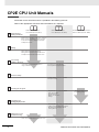 6
6
-
 7
7
-
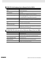 8
8
-
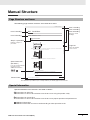 9
9
-
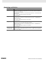 10
10
-
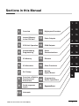 11
11
-
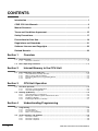 12
12
-
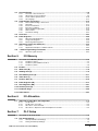 13
13
-
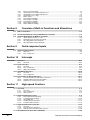 14
14
-
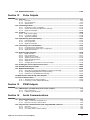 15
15
-
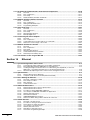 16
16
-
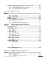 17
17
-
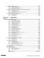 18
18
-
 19
19
-
 20
20
-
 21
21
-
 22
22
-
 23
23
-
 24
24
-
 25
25
-
 26
26
-
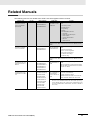 27
27
-
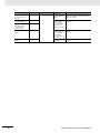 28
28
-
 29
29
-
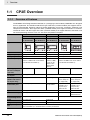 30
30
-
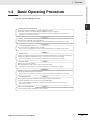 31
31
-
 32
32
-
 33
33
-
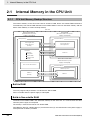 34
34
-
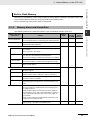 35
35
-
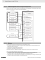 36
36
-
 37
37
-
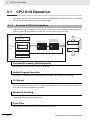 38
38
-
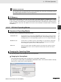 39
39
-
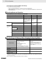 40
40
-
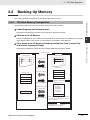 41
41
-
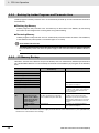 42
42
-
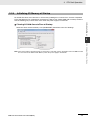 43
43
-
 44
44
-
 45
45
-
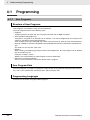 46
46
-
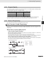 47
47
-
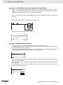 48
48
-
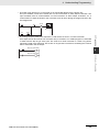 49
49
-
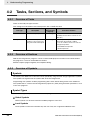 50
50
-
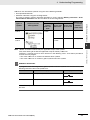 51
51
-
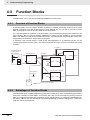 52
52
-
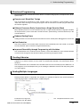 53
53
-
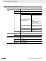 54
54
-
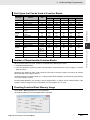 55
55
-
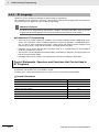 56
56
-
 57
57
-
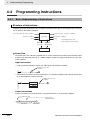 58
58
-
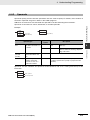 59
59
-
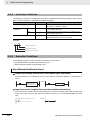 60
60
-
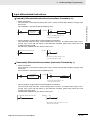 61
61
-
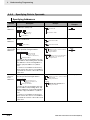 62
62
-
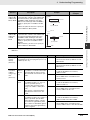 63
63
-
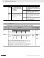 64
64
-
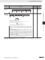 65
65
-
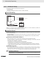 66
66
-
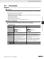 67
67
-
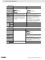 68
68
-
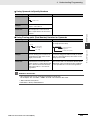 69
69
-
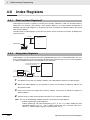 70
70
-
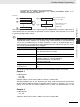 71
71
-
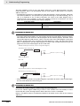 72
72
-
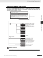 73
73
-
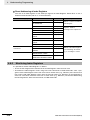 74
74
-
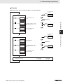 75
75
-
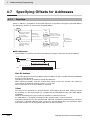 76
76
-
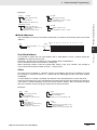 77
77
-
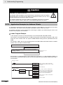 78
78
-
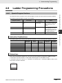 79
79
-
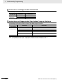 80
80
-
 81
81
-
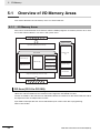 82
82
-
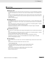 83
83
-
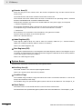 84
84
-
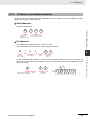 85
85
-
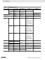 86
86
-
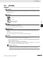 87
87
-
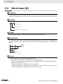 88
88
-
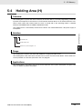 89
89
-
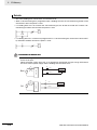 90
90
-
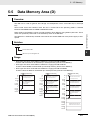 91
91
-
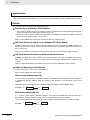 92
92
-
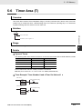 93
93
-
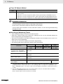 94
94
-
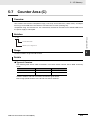 95
95
-
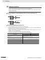 96
96
-
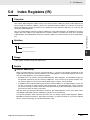 97
97
-
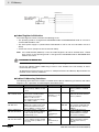 98
98
-
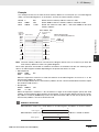 99
99
-
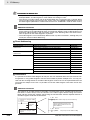 100
100
-
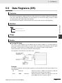 101
101
-
 102
102
-
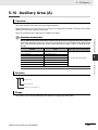 103
103
-
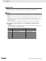 104
104
-
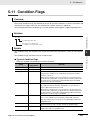 105
105
-
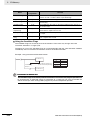 106
106
-
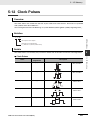 107
107
-
 108
108
-
 109
109
-
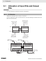 110
110
-
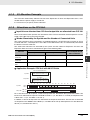 111
111
-
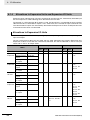 112
112
-
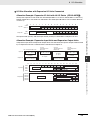 113
113
-
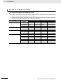 114
114
-
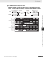 115
115
-
 116
116
-
 117
117
-
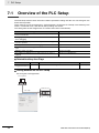 118
118
-
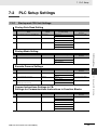 119
119
-
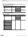 120
120
-
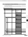 121
121
-
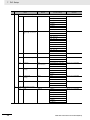 122
122
-
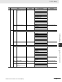 123
123
-
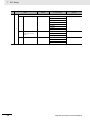 124
124
-
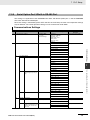 125
125
-
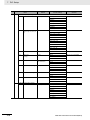 126
126
-
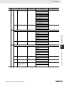 127
127
-
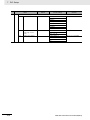 128
128
-
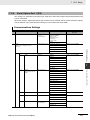 129
129
-
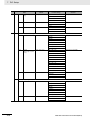 130
130
-
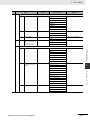 131
131
-
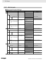 132
132
-
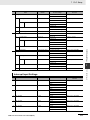 133
133
-
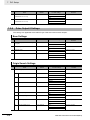 134
134
-
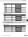 135
135
-
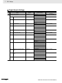 136
136
-
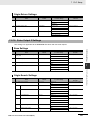 137
137
-
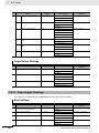 138
138
-
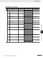 139
139
-
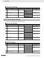 140
140
-
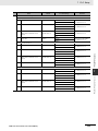 141
141
-
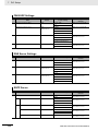 142
142
-
 143
143
-
 144
144
-
 145
145
-
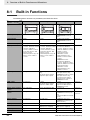 146
146
-
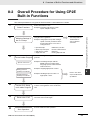 147
147
-
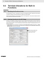 148
148
-
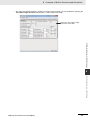 149
149
-
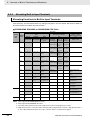 150
150
-
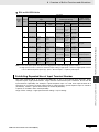 151
151
-
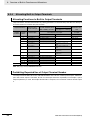 152
152
-
 153
153
-
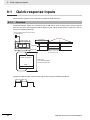 154
154
-
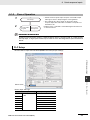 155
155
-
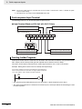 156
156
-
 157
157
-
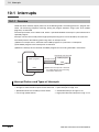 158
158
-
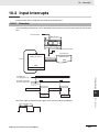 159
159
-
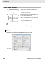 160
160
-
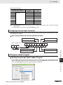 161
161
-
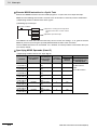 162
162
-
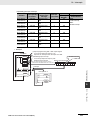 163
163
-
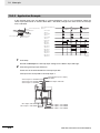 164
164
-
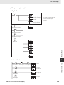 165
165
-
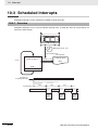 166
166
-
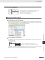 167
167
-
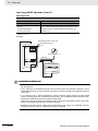 168
168
-
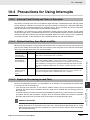 169
169
-
 170
170
-
 171
171
-
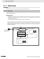 172
172
-
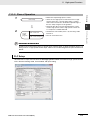 173
173
-
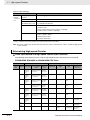 174
174
-
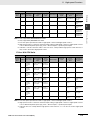 175
175
-
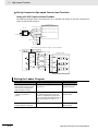 176
176
-
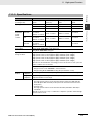 177
177
-
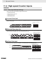 178
178
-
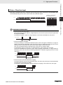 179
179
-
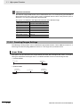 180
180
-
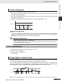 181
181
-
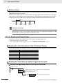 182
182
-
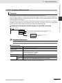 183
183
-
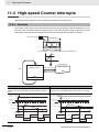 184
184
-
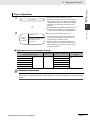 185
185
-
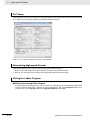 186
186
-
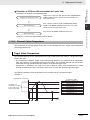 187
187
-
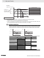 188
188
-
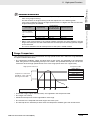 189
189
-
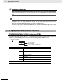 190
190
-
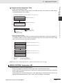 191
191
-
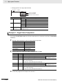 192
192
-
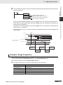 193
193
-
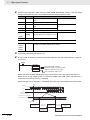 194
194
-
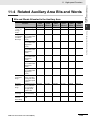 195
195
-
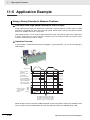 196
196
-
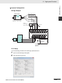 197
197
-
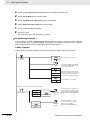 198
198
-
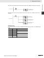 199
199
-
 200
200
-
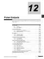 201
201
-
 202
202
-
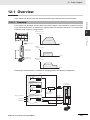 203
203
-
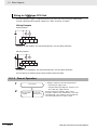 204
204
-
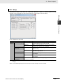 205
205
-
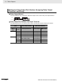 206
206
-
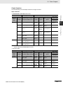 207
207
-
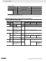 208
208
-
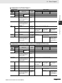 209
209
-
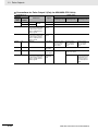 210
210
-
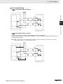 211
211
-
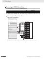 212
212
-
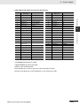 213
213
-
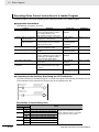 214
214
-
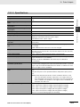 215
215
-
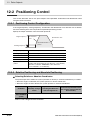 216
216
-
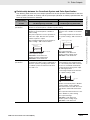 217
217
-
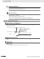 218
218
-
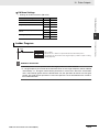 219
219
-
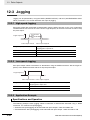 220
220
-
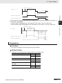 221
221
-
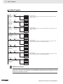 222
222
-
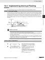 223
223
-
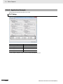 224
224
-
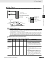 225
225
-
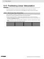 226
226
-
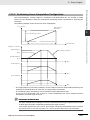 227
227
-
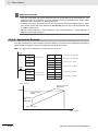 228
228
-
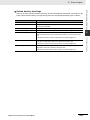 229
229
-
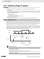 230
230
-
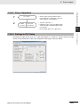 231
231
-
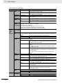 232
232
-
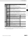 233
233
-
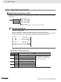 234
234
-
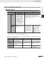 235
235
-
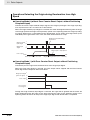 236
236
-
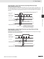 237
237
-
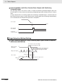 238
238
-
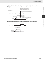 239
239
-
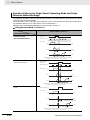 240
240
-
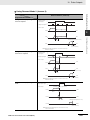 241
241
-
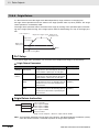 242
242
-
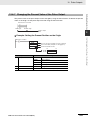 243
243
-
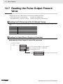 244
244
-
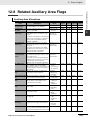 245
245
-
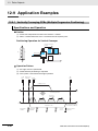 246
246
-
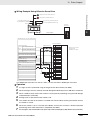 247
247
-
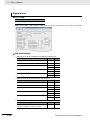 248
248
-
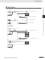 249
249
-
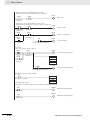 250
250
-
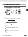 251
251
-
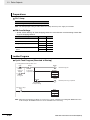 252
252
-
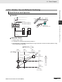 253
253
-
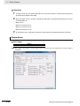 254
254
-
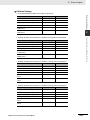 255
255
-
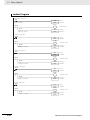 256
256
-
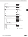 257
257
-
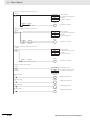 258
258
-
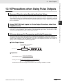 259
259
-
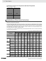 260
260
-
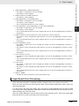 261
261
-
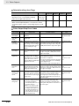 262
262
-
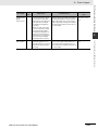 263
263
-
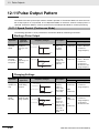 264
264
-
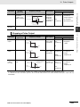 265
265
-
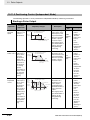 266
266
-
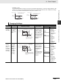 267
267
-
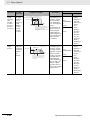 268
268
-
 269
269
-
 270
270
-
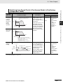 271
271
-
 272
272
-
 273
273
-
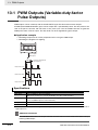 274
274
-
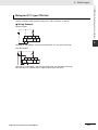 275
275
-
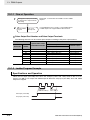 276
276
-
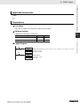 277
277
-
 278
278
-
 279
279
-
 280
280
-
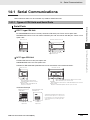 281
281
-
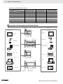 282
282
-
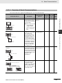 283
283
-
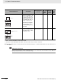 284
284
-
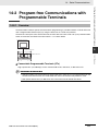 285
285
-
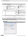 286
286
-
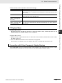 287
287
-
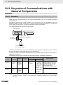 288
288
-
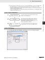 289
289
-
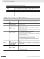 290
290
-
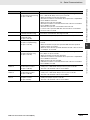 291
291
-
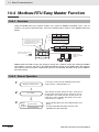 292
292
-
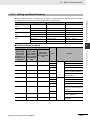 293
293
-
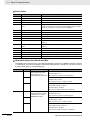 294
294
-
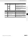 295
295
-
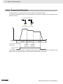 296
296
-
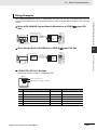 297
297
-
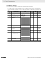 298
298
-
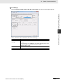 299
299
-
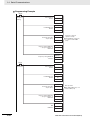 300
300
-
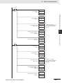 301
301
-
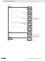 302
302
-
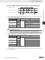 303
303
-
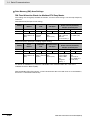 304
304
-
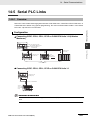 305
305
-
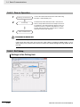 306
306
-
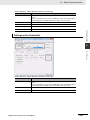 307
307
-
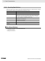 308
308
-
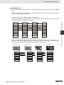 309
309
-
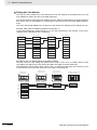 310
310
-
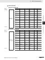 311
311
-
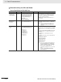 312
312
-
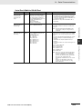 313
313
-
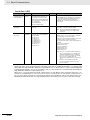 314
314
-
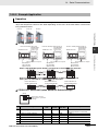 315
315
-
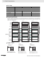 316
316
-
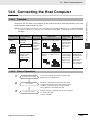 317
317
-
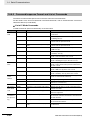 318
318
-
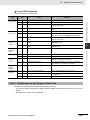 319
319
-
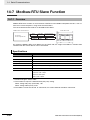 320
320
-
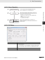 321
321
-
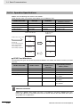 322
322
-
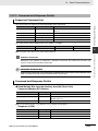 323
323
-
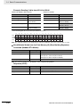 324
324
-
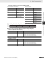 325
325
-
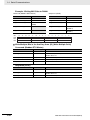 326
326
-
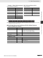 327
327
-
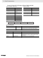 328
328
-
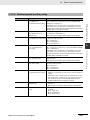 329
329
-
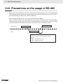 330
330
-
 331
331
-
 332
332
-
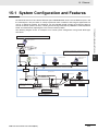 333
333
-
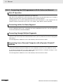 334
334
-
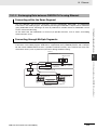 335
335
-
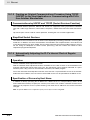 336
336
-
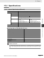 337
337
-
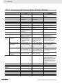 338
338
-
 339
339
-
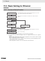 340
340
-
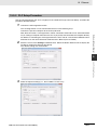 341
341
-
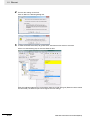 342
342
-
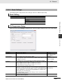 343
343
-
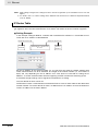 344
344
-
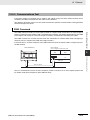 345
345
-
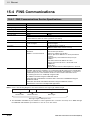 346
346
-
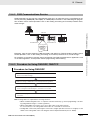 347
347
-
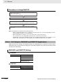 348
348
-
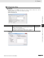 349
349
-
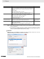 350
350
-
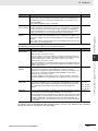 351
351
-
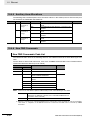 352
352
-
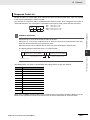 353
353
-
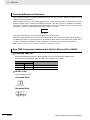 354
354
-
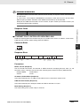 355
355
-
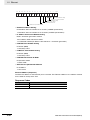 356
356
-
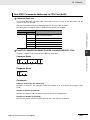 357
357
-
 358
358
-
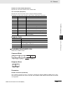 359
359
-
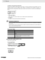 360
360
-
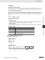 361
361
-
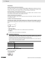 362
362
-
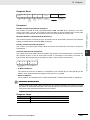 363
363
-
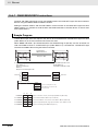 364
364
-
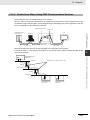 365
365
-
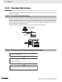 366
366
-
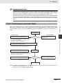 367
367
-
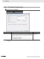 368
368
-
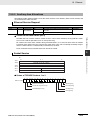 369
369
-
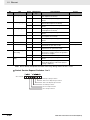 370
370
-
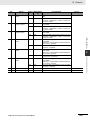 371
371
-
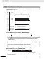 372
372
-
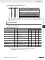 373
373
-
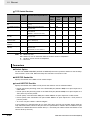 374
374
-
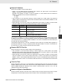 375
375
-
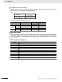 376
376
-
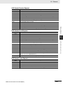 377
377
-
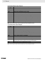 378
378
-
 379
379
-
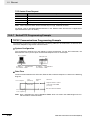 380
380
-
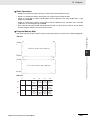 381
381
-
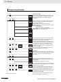 382
382
-
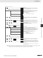 383
383
-
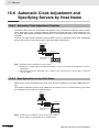 384
384
-
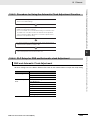 385
385
-
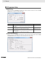 386
386
-
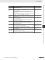 387
387
-
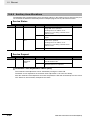 388
388
-
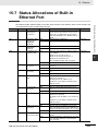 389
389
-
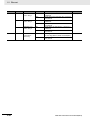 390
390
-
 391
391
-
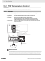 392
392
-
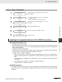 393
393
-
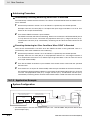 394
394
-
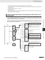 395
395
-
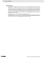 396
396
-
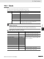 397
397
-
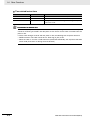 398
398
-
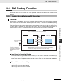 399
399
-
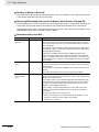 400
400
-
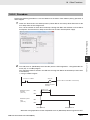 401
401
-
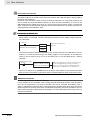 402
402
-
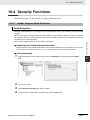 403
403
-
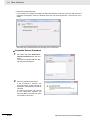 404
404
-
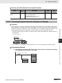 405
405
-
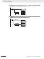 406
406
-
 407
407
-
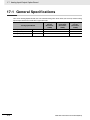 408
408
-
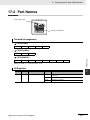 409
409
-
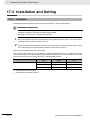 410
410
-
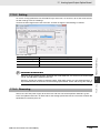 411
411
-
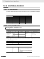 412
412
-
 413
413
-
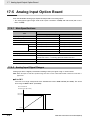 414
414
-
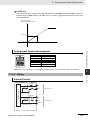 415
415
-
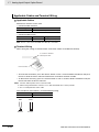 416
416
-
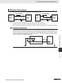 417
417
-
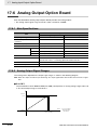 418
418
-
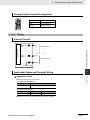 419
419
-
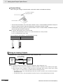 420
420
-
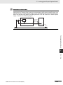 421
421
-
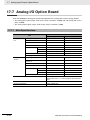 422
422
-
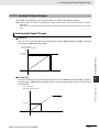 423
423
-
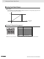 424
424
-
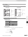 425
425
-
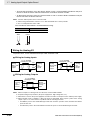 426
426
-
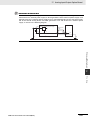 427
427
-
 428
428
-
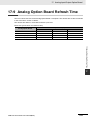 429
429
-
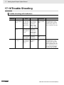 430
430
-
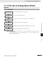 431
431
-
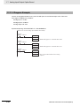 432
432
-
 433
433
-
 434
434
-
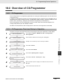 435
435
-
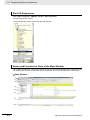 436
436
-
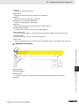 437
437
-
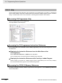 438
438
-
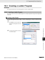 439
439
-
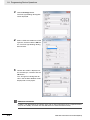 440
440
-
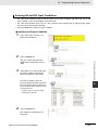 441
441
-
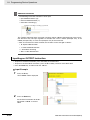 442
442
-
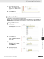 443
443
-
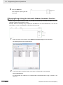 444
444
-
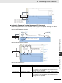 445
445
-
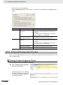 446
446
-
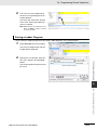 447
447
-
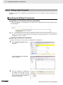 448
448
-
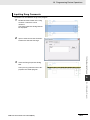 449
449
-
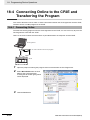 450
450
-
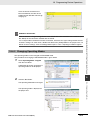 451
451
-
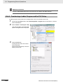 452
452
-
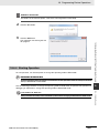 453
453
-
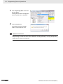 454
454
-
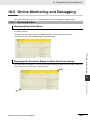 455
455
-
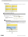 456
456
-
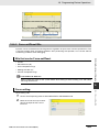 457
457
-
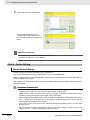 458
458
-
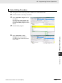 459
459
-
 460
460
-
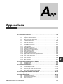 461
461
-
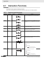 462
462
-
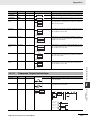 463
463
-
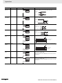 464
464
-
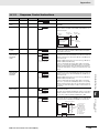 465
465
-
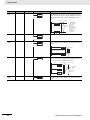 466
466
-
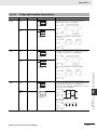 467
467
-
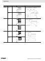 468
468
-
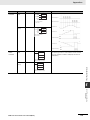 469
469
-
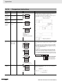 470
470
-
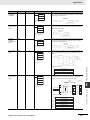 471
471
-
 472
472
-
 473
473
-
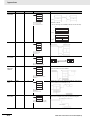 474
474
-
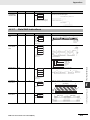 475
475
-
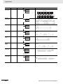 476
476
-
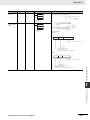 477
477
-
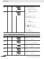 478
478
-
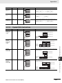 479
479
-
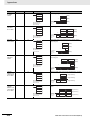 480
480
-
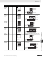 481
481
-
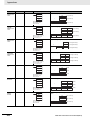 482
482
-
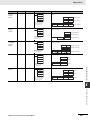 483
483
-
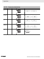 484
484
-
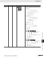 485
485
-
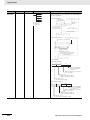 486
486
-
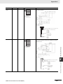 487
487
-
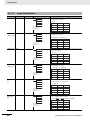 488
488
-
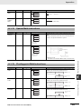 489
489
-
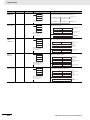 490
490
-
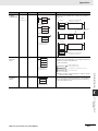 491
491
-
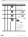 492
492
-
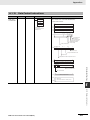 493
493
-
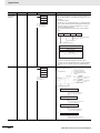 494
494
-
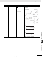 495
495
-
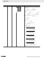 496
496
-
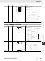 497
497
-
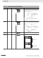 498
498
-
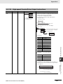 499
499
-
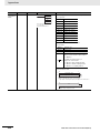 500
500
-
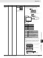 501
501
-
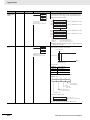 502
502
-
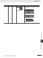 503
503
-
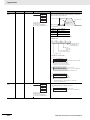 504
504
-
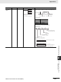 505
505
-
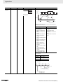 506
506
-
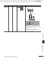 507
507
-
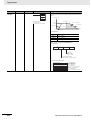 508
508
-
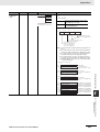 509
509
-
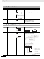 510
510
-
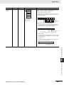 511
511
-
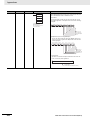 512
512
-
 513
513
-
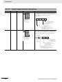 514
514
-
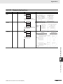 515
515
-
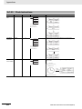 516
516
-
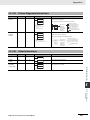 517
517
-
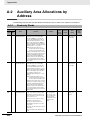 518
518
-
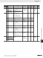 519
519
-
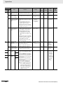 520
520
-
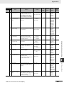 521
521
-
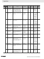 522
522
-
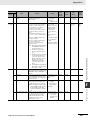 523
523
-
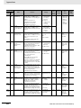 524
524
-
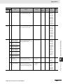 525
525
-
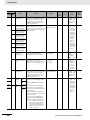 526
526
-
 527
527
-
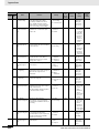 528
528
-
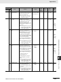 529
529
-
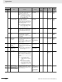 530
530
-
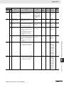 531
531
-
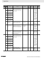 532
532
-
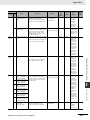 533
533
-
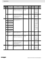 534
534
-
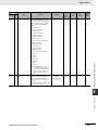 535
535
-
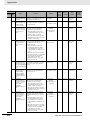 536
536
-
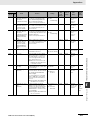 537
537
-
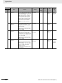 538
538
-
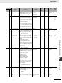 539
539
-
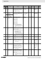 540
540
-
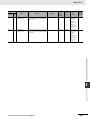 541
541
-
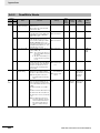 542
542
-
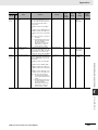 543
543
-
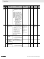 544
544
-
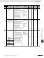 545
545
-
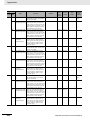 546
546
-
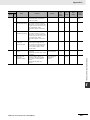 547
547
-
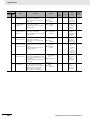 548
548
-
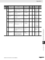 549
549
-
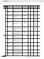 550
550
-
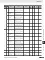 551
551
-
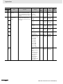 552
552
-
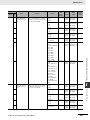 553
553
-
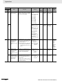 554
554
-
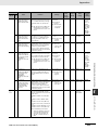 555
555
-
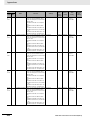 556
556
-
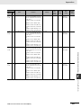 557
557
-
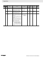 558
558
-
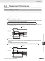 559
559
-
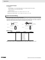 560
560
-
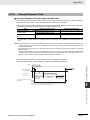 561
561
-
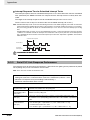 562
562
-
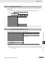 563
563
-
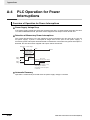 564
564
-
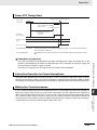 565
565
-
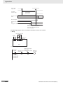 566
566
-
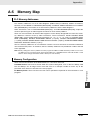 567
567
-
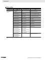 568
568
-
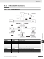 569
569
-
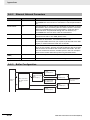 570
570
-
 571
571
-
 572
572
-
 573
573
-
 574
574
-
 575
575
-
 576
576
-
 577
577
-
 578
578


Omron CP2E Programmable Controller User manual
- Type
- User manual
Ask a question and I''ll find the answer in the document
Finding information in a document is now easier with AI
Related papers
-
Omron CP2E Programmable Controller Hardware User manual
-
-
-
-
-
-
-
-
-
Other documents
-
Mitsubishi Electric MELSEC iQ-R Programming Manual
-
Crestron CP2 User manual
-
-
Mitsubishi Electric GOT2000 Series Connection Manual
-
-
 OMRON INDUSTRIAL AUTOMATION CJ2M-MD212 Operating instructions
-
FieldServer Cresnet/IP 8704-21 Owner's manual
-
 Crestron electronic GLS-LCL User manual
-
-

